1
pco.camera
User’s Manual
www.pco.de
This manual covers the following products:
•
CMOS-cameras:
-
•
pco.1200 hs
CCD-cameras:
-
pco.1600
pco.2000
pco.4000
In case of problems or questions not addressed in this
manual, please contact us at PCO. We can be reached
by phone, fax, email or mail:
telephone
+49 (0) 9441 2005 55
fax
+49 (0) 9441 2005 20
email
support@pco.de
mail address
PCO AG
Donaupark 11
93309 Kelheim, Germany
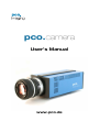
The cover photo shows a pco.camera camera system.
(The lens is sold separately.)
The compliance declaration for EC standards and rules
(EC declaration of conformity) can be found in the appendix of this manual.
Updated December 2004
© PCO AG
Table of Contents
page 3
Table of contents
TABLE OF CONTENTS .......................................... 3
1
INTRODUCTION .......................................... 5
1.1
Target Audience......................................... 5
1.2
Signs and Symbols ..................................... 5
1.3
Safety Instructions ..................................... 5
1.4
Operating Conditions ................................. 6
1.5
Camera Models.......................................... 6
1.6
Installing the “camware” software............. 8
1.7
Imaging Optics Details ............................... 9
2
CAMERA STARTUP.....................................11
2.1
Preparation.................................................11
2.2
Turn on the PC ...........................................11
2.3
Turn on the Camera ...................................11
2.4
Starting Camware ......................................11
3
CAMERA FUNCTIONS................................ 12
3.1
Components and Data Flow...................... 12
3.2
Primary Image Memory (camRAM) .......... 13
3.3
Exposure Control ...................................... 16
1.5.1
1.5.2
1.6.1
1.6.2
1.6.3
1.7.1
1.7.2
3.2.1
3.2.2
3.3.1
3.3.2
What’s in the Box .....................................................7
Data Interfaces.........................................................7
Software Installation from the CD............................ 8
Software Installation via Internet Download ............ 8
Hardware-Driver Installation. .................................. 8
Lens Mount.............................................................. 9
Back Focal Length Adjustment................................ 9
Primary Image Memory Structure .......................... 13
Operating Modes.................................................... 14
3.3.3
3.3.4
3.3.5
Single Image and Sequence Modes ....................... 16
Relationship between Memory Mode, Exposure
Control and Trigger Signals ................................ 16
Time Lapse ............................................................. 18
External Exposure Control Signals ......................... 21
Status Signals ........................................................ 23
3.4
Diagnostics Interface ............................... 24
3.5
Live View .................................................. 24
3.6
CCD Pixel Clocks...................................... 24
3.7
CCD Cooling ............................................. 24
User Manual pco.camera status 12/2004
Table of Contents
page 4
3.8
Color Value Determination ....................... 25
4
DATA INTERFACES ................................... 30
4.1
Interface Structure ................................... 30
4.2
Firewire 400 .............................................. 31
4.3
Camera Link ............................................. 32
4.4
Gigabit Ethernet ....................................... 32
5
SOFTWARE ............................................... 33
5.1
pco.camware ........................................... 33
5.2
Software Development Kit (SDK) ............. 33
5.3
Drivers ...................................................... 33
5.4
Third Party Software Drivers .................... 33
5.5
Firmware Update ..................................... 34
6
SERVICE AND MAINTENANCE ................. 35
6.1
Service ..................................................... 35
6.2
Camera Maintenance............................... 35
7
APPENDIX................................................. 37
7.1
Camera - Mechanical Dimensions ........... 37
7.2
Customer Service ..................................... 41
7.3
Trouble Shooting ....................................... 41
7.4
Camera Disposal...................................... 42
6.2.1
6.2.2
Cleaning the Lens.................................................. 35
Cleaning the Camera’s Input Window ................... 35
User Manual pco.camera status 12/2004
Chapter 1 Introduction
page 5
1
Introduction
The pco.camera system includes:
•
a camera with a digital image output (data interface to
a PC)
•
a separate power supply (pco.power) and
•
image processing and camera control software camware (this software has its own online help.)
The camera is available with various image sensors. Depending on the sensor selected, the camera generates
digital black & white or color images with various spatial
resolutions and exposure times. More detailed information about your new camera can be found in the camera
specific data sheet in the appendix of this manual.
1.1
Target Audience
This camera is designed for use by technicians, engineers
and scientists.
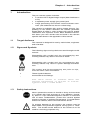
1.2
Signs and Symbols
The following signs and symbols are used throughout this
manual:
Disregarding this symbol and the accompanying text
warning notices may result in the risk of death.
Disregarding this symbol and the accompanying text
warning notices may result in system damage and data
loss.
This symbol and the accompanying text point out tips,
hints and other useful information.
•
-
These Symbols denote
enumerations and listings.
Text which refers to software menus and
related information is written in Courier
typeface with a fixed width.
1.3
Safety Instructions
Never operate the camera in humid or dusty environments
or in places with high amounts of x-ray radiation. Humidity, dust or x-rays could damage the camera. To avoid the
risk of water condensation, protect the camera against
extreme changes of ambient temperature. If condensation
enters the camera, there is the risk electric shock.
To prevent damage to the camera, the system must be
kept stable and protected against strong jolts or vibrations. The socket at the bottom of the camera is to be
used for mounting purposes only.
User Manual pco.camera status 12/2004
Chapter 1 Introduction
page 6
The slits in the camera case (side & back planes) are designed for heat dissipation by the camera fan. To prevent
overheating of the camera, do not block these slits. Do not
leave the camera system in direct sunlight to avoid the risk
of overheating.
Electric shock warning – Never slide any items through the
slits into the camera because of the risk of electric shock if
the voltage parts inside are touched.
Each time the camera is used, check the power cable for
any damage. Never position the cable in a way that it
could become a tripping hazard.
If any of the following conditions apply, immediately switch
the camera off, separate it from the power line and contact
our customer support:
•
If the power cable or the power plug seems to be worn or
damaged.
•
If liquids have penetrated the device.
•
If, after thoroughly reviewing the instruction manual, the device is still not operating properly.
•
If the camera has been dropped or the casing is damaged.
•
If the device is not operating normally.
Do not force the lens onto the camera. To protect the lens
connector thread from damage, use minimal force when
attaching a lens to the camera.
1.4
Operating Conditions
The camera must be connected to a PC in order to operate. Minimum system requirements are:
•
Clock speed > 1.6GHz
•
RAM > 256MB (for pco.4000 >=512MB)
•
Windows XP/ Service Pack 1 or Win2000/ Service
Pack 4
For Linux or MacOS appropriate drivers will be developed in the near future. If you are interested in these
drivers, please monitor our website: www.pco.de or contact us (see page 2).
1.5
•
graphics card and 1280 x 1024 pixel resolution display
•
32-bit-graphics card (16.7 million colors)
Camera Models
The following camera systems are available:
•
pco.1200 hs, 1280 x 1025pixel, with monochrome or
color CMOS image sensor, camRAM (various sizes),
selectable data interface
•
pco.1600, 1600 x 1200pixel, with monochrome or
color CCD image sensor, camRAM (various sizes), selectable data interface
User Manual pco.camera status 12/2004
Chapter 1 Introduction
page 7
•
pco.2000, 2048 x 2048pixel, with monochrome or
color CCD image sensor, camRAM (various sizes), selectable data interface
•
pco.4000, 4032 x 2688pixel, with monochrome or
color CCD image sensor, camRAM (various sizes), selectable data interface
Depending on the model, the camera system generates
images with 1024 (10bit) or 16384 (14bit) gray levels. The
monochrome images on a display or monitor always use
256 gray levels (except special screens) and the color
presentation with color cameras uses 16.7 million colors
(3x8bit).
Usually there are multiple graphics settings available on
one graphics card in a computer. We recommend using
24 or 32 bit with 16.7 Million colors. If the 256-color
mode in Windows is set, Windows uses 20 colors internally. Therefore in this operating mode only 236 gray levels are available for display. For this reason, only 7bits
are taken for monochrome display. Some older graphics
cards only use 6 bits for monochrome display in 256color mode, resulting in 64 gray levels, which can be
displayed on the screen.
1.5.1
What’s in the Box
The pco.camera system includes the following components:
1.5.2
•
camera (without lens),
•
pco.power supply,
•
camera-power supply connecting cable,
•
camera-PC data cable,
•
power cable for the power supply,
•
CD with user's manual, camware application software, hardware-driver, software development kit
(SDK) and demo programs in C++
Data Interfaces
The cameras are equipped with one of the following data
interfaces:
•
IEEE 1394a Firewire with a minimum 400Mb Firewire
interface card or better
•
Camera Link Frame Grabber: the pco.camera system
was successfully tested with the following Camera
Link frame grabber:
-
•
microEnable III, Silicon Software (www.silicon-software.de)
Matrox Helios XCL, Matrox (www.matrox.com)
Ethernet or Gigabit Ethernet – 1000baseT
For further information please contact the PCO support
department under support@pco.de or have a look to our
website: www.pco.de
User Manual pco.camera status 12/2004
Chapter 1 Introduction
page 8
1.6
Installing the “camware” software
Camware 32-bit Windows application software can control every camera parameter or setting. Images can be
displayed on a monitor and may be downloaded and
stored. Detailed information about camware can be found
by accessing the software's help section.
The camware software is located on the enclosed CD. If
you do not have the CD, you may download the latest
version from our website: www.pco.de at no charge.
In case of installation problems, we will be pleased to assist you. Please contact us by phone +49 (0) 9441 2005
55, fax +49 (0) 9441 2005 20 or email support@pco.de.
1.6.1
Software Installation from the CD
After insertion into the computer, if the CD does not run
automatically, please begin the installation manually by
double clicking on the starter.exe file. Select the corresponding camera and the camware software.
1.6.2
Software Installation via Internet Download
Please download the camware from the internet into any
computer directory. As the files are compressed, it is
necessary to decompress these files with an appropriate
program (e.g. WinZip or the like). After decompression,
start the installation by double clicking on starter.exe.
More detailed information about the camware installation
is found in the readme.txt file. You must have power user
or administrator rights for Windows XP to properly install
camware.
After installation, please restart/reboot your computer!
The installation software copies all necessary DLL files
into the corresponding Windows directories. While doing
this, older versions of these files will be replaced, if present. All required Windows registration entries will be
made automatically. To uninstall the camware program,
select the following:
Start - Settings – System Control - Software
After a successful installation, you will find the program
file’ Digital Camera Toolbox’ in your program directory.
From there, you can start camware. Other helpful tools
are also installed in the same file
1.6.3
Hardware-Driver Installation.
FireWire 400
The drivers for firewire interfaces or cards are part of
Windows XP or part of the board manufacturer package.
The installation of an additional hardware driver for the interface is not necessary.
The first time the camera is connected via firewire to the
computer, Windows will notify the user that a new device
User Manual pco.camera status 12/2004
Chapter 1 Introduction
page 9
has been detected. Afterwards, the typical Windows
hardware drivers’ installation process will begin. At this
point, you are asked for the location of the corresponding
*.inf file. Please click on the drive where the CD has been
inserted or to the directory where the installation software
has been downloaded. Windows will perform any further
installation and system registration automatically.
Camera Link
The hardware driver required for the Camera Link frame
grabber is found as part of the frame grabber setup package, and should be available from the frame grabber
manufacturer. Installation instructions for the hardware
driver should be available in the frame grabber instruction
manual.
Ethernet and Gigabit-Ethernet
Drivers for ethernet interfaces or interface cards may be
found as part of the Windows XP operating disk or are
available with the frame grabber materials. The installation
of any additional hardware drivers should not be necessary.
1.7
Imaging Optics Details
1.7.1
Lens Mount
The pco.camera family is supplied with either a standard
C-mount or a Nikon F-mount adapter. For image sensor
formats of 1/3“, 1/2“ and 1“ we recommend the use of Cmount lenses. For the 1-1.5“ range there are special Cmount lenses available, but most often, F-Mount lenses
should be used. For cameras with a sensor format larger
than 1.5” (pco.4000), only F-mount lenses should be
used. The distance between the front edge of the CMount and the CCD sensor is 17.52 mm. Change the distance of the lens, support plate to the Image Sensor.
1.7.2
Back Focal Length Adjustment
In some cases, it may be necessary to change the distance of the lens support plate to the image sensor (e.g.,
if the camera cannot be focussed in the infinite position).
Use the small Allen wrench included in the camera package for this purpose and follow the directions below,
based on your adaptor type.
C-mount-adaptor
Loosen the two Allen screws, located at the steel insert in
the front of the camera case and adjust the knurled insert
(M50 x 0.5 thread) to the correct distance between lens
support plate and the image sensor. If you want to adjust
for the infinite position of the lens, the lens must be set to
infinite before you begin. Then the knurled insert can be
adjusted with the connected lens until you see a sharp
image, with the camware software in recording mode or
with Live View running.
User Manual pco.camera status 12/2004
Chapter 1 Introduction
page 10
After finishing the adjustments, tighten the two Allen
screws.
F-mount-adaptor
Begin by loosening the Allen screw, which is in the hole of
the knurled ring around the F-mount adaptor (close to the
camera front plate). The distance between the lens support plate and the image sensor can be changed by turning the total F-mount adaptor. If you want to adjust for the
infinite lens position, the lens must be set to infinite before
you begin. Then the F-Mount adaptor can be adjusted
with the connected lens until you see a sharp image, with
the camware software in recording mode or with Live
View running.
After finishing the adjustments, tighten the Allen screws.
User Manual pco.camera status 12/2004
Chapter 2 Camera Startup
page 11
2
Camera Startup
2.1
Preparation
1.
Check that the following cable connections have been
made:
camera is connected to the power supply via a special
cable;
camera is connected to the PC via a corresponding
interface cable;
pco.power is connected via an appropriate power cable to
the power line;
-
2.
2.2
Check if the lens is properly tightened (C-mount) or inserted (F-mount).
Turn on the PC
Turn on the connected PC.
2.3
Turn on the Camera
Turn on the camera system by pressing the main power
switch on the front panel of pco.power and look for the
power and status-LED lights. The power light displays the
operating status of the power supply, while the status
light displays the operating status of the camera. The displays are coded as follows:
power-display:
•
orange flashing light:
•
selftest power supply
•
green permanent light:
•
normal operating status
•
red flashing light:
•
error
status-display:
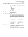
2.4
•
orange flashing light:
•
selftest camera
•
green permanent light:
•
normal operating status
•
green-orange flashing light:
•
exposure display
•
red flashing light:
•
error
Starting Camware
To start the camware software program, look in the appropriate computer directory for the following:
Programs – Digital Camera ToolBox
More information about camware is available in camware’s online help.
User Manual pco.camera status 12/2004
Chapter 3 Camera Functions
page 12
3
Camera Functions
More detailed information on the pco.camera system, its
multiple exposure control options, integrated image memory, and various operating modes is contained in the
following chapters.
3.1
Components and Data Flow
The pco.camera system consists of the camera and the
pco.power supply and exposure control unit:
CCD
Peltier cooler
analog
pco.camera
camRAM
digital
control
interface
pco.power
power unit
digital
control
trigger unit
PC
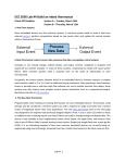
Figure 3.1:
Structural overview of the pco.camera system components
Inside the camera, photons are converted into charges by
the image sensor (see Figure 3.1, CCD or CMOS). Depending on the type of camera, the image sensor is
cooled by a thermo-electrical Peltier cooler, to reduce the
accumulation of dark charges (only relevant for long exposures) and to prevent thermally induced changes in the
offset of readout images.
After multiple shift processes (in case of the CCD image
sensor) these charges are analog processed (see Figure
3.1, analog) and converted into digital signals. They are
then transferred at very high data rates into the primary
image memory of the camera (see Figure 3.1, camRAM,
CCD – 160MB/s). In the memory, they are stored as image data. Depending on the selected operating mode (see
Figure 3.1, pco.camera - digital control), they are stored
or transmitted via a data interface to a PC (see Figure 3.1,
interface).
The power supply (see Figure 3.1, pco.power) provides
the required energy. This power supply also has other
functions (see Figure 3.1, power unit):
•
The power supply has all of the external connections
for exposure control (see Figure 3.1, trigger unit), and
•
The power supply controls the pre-set temperature at
the image sensor (see Figure 3.1, pco.power – digital
control).
The structure of the system makes it possible to set the
camera into recording mode via a PC, disconnect the PC
User Manual pco.camera status 12/2004
Chapter 3 Camera Functions
page 13
and reconnect it later. Further, the image memory in the
camera enables (see Figure 3.1, pco.camera – camRAM)
extended operating modes (e.g. ring buffer operation). In
this mode, images are continuously recorded and, as the
memory is filled, the oldest image data are overwritten.
Once the event finishes, it is possible to stop the recording process and the event will reside in the memory,
as well as a certain amount of time before the event.
Once recording is finished, the user can stop the recording process and keep it in memory as well as a certain time before the event. In the following sections, single
components image memory, Live-View, CCD readout,
CCD cooling and color display are described in more detail.
3.2
Primary Image Memory (camRAM)
The primary image memory (camRAM) of the camera system is integrated into the camera.
3.2.1
Primary Image Memory Structure
The image memory is divided into four memory segments
that accept images (see Figure 3.2). The user determines
the size of the segments.
Information about the delivered camera’s image memory
size is found in the camera specific data sheet in the appendix of this manual.
Camware application software uses one of the segments
for Live-View and other display purposes. If camware is
used, only three segments are available for customer
specification.
camRAM
Figure 3.2:
memory segment 1
memory segment 2
memory segment 3
memory segment 4
Illustration of the camera’s primary image memory (camRAM.
The image memory is divided into four memory segments
(memory segment 1-4), which accepts the images for storage.
The size allocation of each segment is completely userselectable (see Figure 3.3). It is also possible to set the
size of a segment to zero. The format of the images to be
stored, might differ from segment to segment. Within the
same segment the image format is fixed, meaning that total images, binned images or ROIs have to be stored in
different segments.
User Manual pco.camera status 12/2004
Chapter 3 Camera Functions
page 14
camRAM
memory segment 1
memory
segment 2
Figure 3.3:
memory
segm. 3 memory segment 4
Illustration of a sample camRam (primary image memory)
segmentation in the camera. Various configurations are possible
for the four memory segments to record various image formats,
binning modes or ROIs. The image format is fixed within the
same segment.
The image memory segment size is determined by both
the number of images it can accept, as well as by the
smallest possible memory unit, a page. The size of this
page is 1280 pixel for CCD image sensors and 3584 pixel
for CMOS image sensors.
memory segment 1
page
Figure 3.4:
Ilustration of one memory segment (e.g. memory segment 1). In
this example, he images are stored, where the smallest memory
unit is a "page", i.e. each image has to be an integer multiple of
this basic memory unit page.
Therefore the memory demand for a total image always
must be an integer multiple of this basic unit.
3.2.2 Operating Modes
There are two basic operating modes for the camRAM:
-
FIFO buffer
Record mode
FIFO BufferMode
In the buffer or FIFO buffer (FIFO = first in first out) mode,
the camera records and stores image data while simultaneously transmitting this image data to the computer.
User Manual pco.camera status 12/2004
Chapter 3 Camera Functions
page 15
PC
camRAM
1
2
6
3
7
4
5
8
CCD
Figure 3.5:
Illustration FIFO buffer mode.
If the camera reaches the end of the memory segment, it
starts to fill the memory space from the start, which has
been released due to image data transmission (see Figure
3.5). If the camera catches up with the readout process, it
automatically slows down the recording rate. Stored images will not be overwritten before they are transmitted to
the computer.
Record Mode
In record mode the camera only records and stores images. It is only possible to transfer the image data to the
computer after the recording is finished. However, if the
Live-View function (see chapter 3.5) is used, it is possible
to follow the recorded images with the speed of the integrated data interface. In record mode there are two possibilities:
-
sequential operation
ring bufferoperation
1. Sequential Operation (camware: sequence)
camRAM
1
2
3
6
7
8
4
5
full
CCD
Figure 3.6:
Illustration of record mode - sequential operation.
In sequential record operation, the image data are continuously written to the memory segment, until either the
user stops the recording or until the segment is filled (see
Figure 3.6, full).
User Manual pco.camera status 12/2004
Chapter 3 Camera Functions
page 16
2. Ring Buffer (camware – ring buffer)
camRAM
1
2
6
3
7
4
5
8
CCD
Figure 3.7:
Illustration of record mode - ring buffer operation.
During ring buffer operation, the memory segment is also
filled up. Cyclical writing to the memory segment occurs if
the camera reaches the end of the segment when it will
overwrite the oldest images (see Figure 3.7).
3.3
3.3.1
Exposure Control
Single Image and Sequence Modes
Generally there can be two image recording operating
modes:
-
single image recording, also called asynchronous or still
operation
image sequence recording, also called video, sequential or
synchronous operation
For single image recording each image is recorded after
the appropriate trigger signal starts the recording.
For sequential recording, the camera determines the fastest possible image uptake rate depending on the adjusted
delay and exposure times and the required readout time.
The trigger can only control the beginning and end of the
image sequence. As a series of single images could also
become a sequence, there is a smooth transition between
these operating modes. It is possible to allow the camera
to determine the optimal fastest image rate to the camera.
Otherwise, the optimal sequential image recording is controlled with the help of properly adjusted single-imagetrigger signals.
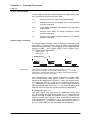
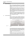
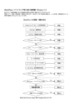
3.3.2 Relationship between Memory Mode, Exposure Control and
Trigger Signals
The trigger mode of the camera depends on the memory
mode selected, as well as the exposure control and the
trigger signals.
For sequential recording the [auto sequence] exposure
control mode should be used.
To record single images, the camera provides the following exposure control modes: [soft trigger], [exposure trigger start] and [exposure trigger control].
User Manual pco.camera status 12/2004
Chapter 3 Camera Functions
page 17
auto sequence
In the [auto sequence] exposure control mode, the camera determines the fastest possible image uptake rate depending on the adjusted delay and exposure times and
the required readout time. After a start command is given,
the sequential recording is started until a stop command
is given. If the sequential recording is active, the recording can only be interrupted by a negative external
signal: [acq. enbl.] (acquire enable). Before each image of
a sequence is recorded, the camera checks the status of
the [acq. enbl.] whether or not it is valid and if it has been
previously initialized.
soft trigger
In the [soft trigger] exposure control mode, a single image
recording is forced by a software command. In the camware application software, this is done by clicking on the
corresponding record button. Other signals cannot influence this operating mode.
exp. trigger start
In the [exp. trigger start] exposure control mode, single
image recording is started by the trailing or rising edge of
the voltage signal at the BNC input [exp. trig.] (see Figure
3.17 on page 22). Additionally, if it has been initialized, the
status of the [acq. enbl.] signal at the BNC input is
checked. Therefore, both signals are important for image
recording.
exp. trigger ctrl.
In [exp. trigger ctrl.] exposure control mode, single image
recording is controlled by the time length of the BNC input signal [exp. trig.] (see Figure 3.17 on page 22). The
exposure time is determined by the signal (depending on
the DIP switch setting to a positive or negative voltage
level). Additionally, if it has been initialized, the status of
the [acq. enbl.] signal at the BNC input is checked. Therefore both signals are important for image recording.
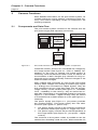
Figure 3.8 shows the relationship between the various
memory operating modes (camRAM modes), exposure
control (trigger modes) and the chance to control the
camera via external trigger signals (external signal options).
camRAM modes
FIFO-buffer
recorder - sequential
recorder - ring buffer
FIFO-buffer
recorder - sequential
recorder - ring buffer
FIFO-buffer
recorder - sequential
recorder - ring buffer
FIFO-buffer
recorder - sequential
recorder - ring buffer
Figure 3.8:
trigger modes
}
}
}
}
external signals
acq enbl
auto sequence
soft trigger
exp. trigger start
exp trig
acq enbl
exp. trigger ctrl.
exp trig
acq enbl
Relationship between the memory operation mode, exposure
control and trigger signals
User Manual pco.camera status 12/2004
Chapter 3 Camera Functions
page 18
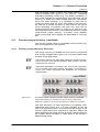
3.3.3 Time Lapse
In this chapter the time-lapse feature is explained in detail. The following acronyms are used:
texp
Exposure time for one image (adjustable)
tread
Readout time for one image (from CCD-sensor)
(system inherent)
tdelay
Time delay between start-signal and exposure
(adjustable)
tsys
Internal time delay in image sequence mode
(system inherent)
tid
Internal time delay before exposure is started
(system inherent)
Single image recording
To record single images, each recording is started by its
own start- or trigger-event, which is either generated by
software (trigger mode - [soft trigger]) or by trigger signals
(trigger modes - [ext. trigger start] or [ext. trigger ctrl.]).
Two options are discussed:
-
delay time t = 0
delay time t > 0
delay
delay
1. Delay time tdelay = 0
texp
tid
tread
time
Figure 3.9:
Time lapse illustration of the image recording for the
asynchronous image recording and delay time tdelay = 0 mode.
The arrows indicate the beginning of each recording sequence
(the times are not drawn to scale).
The internal time tid (see Figure 3.) begins to elapse after
the corresponding start signal, which is actually much
shorter than displayed in Figure 3.. Then, the actual exposure starts for time texp. After texp the image is read out for
tread. Depending on the application, a new image recording
can be started after read out tread. The internal delay time
and the read out time are system inherent parameters.
2. Delay time tdelay > 0
The start signal can also start an additional delay time
tdelay preceding the actual exposure, if it is required (see
Figure 3.1010). It takes the internal time tid similar to the
earlier example (see Figure 3.1010, shorter than displayed
in the illustration in relation to texp or tread) and then the actual exposure texp is started. Finally the image is read out
for tread. Afterwards, a new recording can be started.
User Manual pco.camera status 12/2004
Chapter 3 Camera Functions
page 19
tdelay
texp
tid
tread
time
Figure 3.10:
Time lapse illustration of the image recording for the
asynchronous image recording and delay time tdelay > 0 mode.
The arrows indicate the beginning of each image recording
sequence (the times are not drawn to scale).
Image sequence
As opposed to single image recording, sequential image
recording is started by a software start signal (trigger
mode - [auto sequence]) and subsequent images are
quickly recorded in a sequence with the highest possible
quality. The camera determines the optimum exposure
control depending upon the adjusted exposure time texp
and the delay time tdelay. To stop the sequential recording,
the stop button must be clicked. Sequential exposure
control offers six different settings:
-
delay time t = 0 with
delay
-
t =t
t >t
t <t
exp
read
exp
read
exp
read
delay time t > 0 with
delay
-
t = (t + t )
t > (t + t )
t < (t + t )
exp
read
delay
exp
read
delay
exp
read
delay
{tdelay - delay time, texp - exposure time, tread - readout time}
In the case of no delay time, tdelay = 0, images can be recorded immediately, one after another. However, the user
must consider whether the exposure time is smaller, larger or equal to the readout time.
If the application requires a delay time tdelay > 0 for image
sequence recording, the user must remember that the delay time is inserted after the readout time, tread, as opposed to the asynchronous mode, where it is inserted before the exposure. Again, the user must consider whether
the exposure time is smaller, larger or equal to the readout time.
delay time tdelay = 0
exposure time texp = readout time tread
texp
tread
time
Figure 3.11::
Time lapse illustration of image recording for the described
settings. The arrow indicates the beginning of the image
recording sequence (the times are not drawn to scale).
The optimal conditions for sequential recording, resulting
in the fastest possible image recording are when the exposure time texp equals the system inherent readout tread,
(see Figure 3.11).
User Manual pco.camera status 12/2004
Chapter 3 Camera Functions
page 20
delay time tdelay = 0
exposure time texp > readout time tread
texp
tread
time
Figure 3.12:
Time lapse illustration of image recording for the settings
described above. The arrow indicates the beginning of the image
recording sequence (the times are not drawn to scale).
For sequential recording, if the exposure time texp is longer
than the readout time tread it determines the frame rate.
delay time tdelay = 0
exposure time texp < readout time tread
tsys texp
tread
time
Figure 3.13:
Time lapse illustration of image recording for the settings
described above. The arrow indicates the beginning of the image
recording sequence(the times are not drawn to scale).
If the exposure time texp is shorter than the readout time
tread (see Figure 3.13), the camera inserts a system delay
time tsys before the actual exposure time, such as tsys and
texp equal the readout time. In this case the readout time
determines the frame rate.
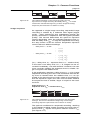
delay time tdelay > 0
exposure texp = (readout tread + delay tdelay)
texp
tread
tdelay
time
Figure 3.14:
Time lapse illustration of image recording for the settings
described above. The arrow indicates the beginning of the image
recording sequence (the times are not drawn to scale).
For applications requiring a delay time, the fastest possible frame rate for sequential recording is achieved if the
exposure time texp equals the sum of the readout time tread
and the adjusted delay time tdelay (see Figure 3.14).
User Manual pco.camera status 12/2004
Chapter 3 Camera Functions
page 21
delay time tdelay > 0
exposure texp > (readout tread + delay tdelay)
texp
tread
tdelay
time
Figure 3.15:
Time lapse illustration of image recording for the settings
described above. The arrow indicates the beginning of the image
recording sequence (the times are not drawn to scale).
If the exposure time texp is larger than the sum of readout
time tread and delay time tdelay, it determines the maximum
frame rate (see Figure 3.15).
delay time tdelay > 0
exposure texp < (readout tread + delay tdelay)
tsys
texp
tread
tdelay
time
Figure 3.16:
Time lapse illustration of image recording for the settings
described above. The arrow indicates the beginning of the image
recording sequence (the times are not drawn to scale).
If the exposure time texp is smaller than the sum of the
readout time tread and the delay time tdelay, the frame rate is
determined by this sum (see Figure 3.16). The camera inserts its own system inherent delay time tsys preceding the
actual exposure.
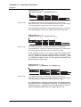
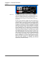
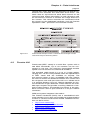
3.3.4 External Exposure Control Signals
External signals can influence three of the four available
exposure control modes (see chapter 3.3.2). These signals must be inputted into the BNC sockets [control in] at
the back panel of the power supply (see Figure 3.17). The
allowable signal types and how they are processed are
explained in more detail below.
On the back panel of the pco.power unit, there are two
signal inputs available (BNC sockets).
User Manual pco.camera status 12/2004
Chapter 3 Camera Functions
page 22
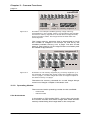
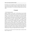
Figure 3.17:
Diagram of the back plate of the power supply, pco.power:
input signal BNC sockets: control in - [exp trig] and [acq enbl]
output signal BNC sockets: status out - [exp] and [busy]
DIP-switch: voltage level selection, polarity selection and edge
selection for input signals, connection socket to camera,
connection socket to diagnostic interface: RS232, power plug:
90-260 VAC
At [exp. trig.] (exposure trigger) the [start exposure] or
control signal has to be supplied. This is a dynamic (edge
triggered) signal. The input is internally wired with a resistor of Ri = 10kΩ versus signal ground. The voltage level of
the [exp. trig.] signal is selected by putting the DIP switch
in position 1: TTL level or 10-15V. If a positive or negative
signal controls the exposure, after initialization of the [exp.
trig. start] operation mode, the DIP switch is in position
2.The image acquire control signal is fed in at [acq. enbl.]
(acquire enable). This is a static signal (level triggered).
The input is wired internally with a resistor of Ri = 10kΩ
versus signal ground. Position 4 of the DIP switch selects
the voltage level of the [acq. enbl.] signal: TTL level or 1015V. After initialization of the [acq. enbl.], with the DIP
switch in position 3, the user can choose whether the signal is HIGH or LOW active, which is different depending
on the voltage level settings (see Figure 3.17). If [acq.
enbl.] is initialized, i.e. it is not on [auto], before every exposure, the status of the [acq. enbl.] signal is checked,
since this signal "enables" or "disables" the exposure
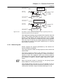
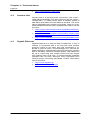
start signals. The following figure illustrates how the input
signals are processed internally:
User Manual pco.camera status 12/2004
Chapter 3 Camera Functions
page 23
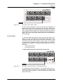
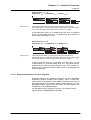
trigger edge
2 - ON: rising
2 - OFF: trailing
select edge type
DIP switch 2
exp trig
BNC input
Ri = 10kW
select logic level
DIP switch 3
select sensitivity
DIP switch 4
Figure 3.18:
+
1
1.7V
+
2
1
exposure trigger
(internal)
2
trigger sensitivity
1 - ON: TTL level
1 - OFF: 10-15V
select sensitivity
DIP switch 1
acq enbl
BNC input
6.7V
Ri = 10kW
acq. enable logic level
3 - ON: HIGH (>2V or 7V)
3 - OFF: LOW (<1.5V or 6.5V)
6.7V
+
1
1.7V
+
2
1
acquire enable
(internal)
2
acq. enbl. sensitivity
4 - ON: TTL level
4 - OFF: 10-15V
Illustration of the signal processing of input signals [control in]
and their external control features
The signal processing internal sequence requires that the
[acq. enbl.] signal precedes the [exp. trig.] and subsequently comes before the actual exposure, as an invalid
[acq. enbl.] can prevent an exposure from being started.
The only way to interrupt an image sequence recording in
the exposure control mode [auto sequence] is to use the
[acq. enbl.] command.
3.3.5 Status Signals
Status signals are signals generated by the camera for
synchronization purposes.
The [exp] signal is HIGH during exposure and LOW at all
other times.
The [busy] signal is active if the camera is recording or
when it is switched on. Occasionally, a “false or low busy”
signal is read. This happens when the camera setup is
complete and no trigger has been detected, meaning that
the camera is ready to receive trigger signals for exposures.
When the camera system is switched on, the [busy] signal
reads HIGH for a short period of time.
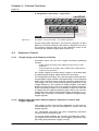
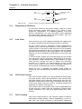
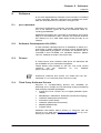
The signals [status out] pass as +5V TTL signals to a 27 Ω
output resistor (short circuit protection) and they are provided at the two BNC output sockets (see Figure 3.19).
User Manual pco.camera status 12/2004
Chapter 3 Camera Functions
page 24
+5V
exp
BNC output
Ro = 27W
exposure signal
(internal)
+5V
busy
BNC output
Figure 3.19
3.4
Ro = 27W
busy signal
(internal)
Output signal processing diagram [status out].
Diagnostics Interface
On the back panel of the power supply, there is a serial
data connector socket (see Figure 3.17), which is integrated for diagnostics. It is labeled [RS232]. The PCO
service department can get information here regarding
the status and settings of the camera system. The customer should ignore this interface.
3.5
Live View
The camera’s [Live-View] feature provides the opportunity
to watch and follow the recording process in real time.
Of the various memory operating modes (presented in
chapter 3.3.2), the live view feature is only available in the
record mode. In the FIFO mode, live view is not available,
as the data transmission line is occupied with the fastest
possible transmission of the image data to the computer.
There is no time available for transmission of the live view
images.
In record mode, images are recorded and they are written
into the active memory segment, depending on the memory operation mode’s [sequential] or [ring buffer]. The [live
view] function allows the user to follow the recording
process on a monitor. For that purpose, a copy of the
most recent image is sent via the integrated interface to
the computer for display (at maximum 200 MB/s).
When live view is applied, the speed of the image recording is not compromised, because recording has priority.
3.6
CCD Pixel Clocks
The CCD camera system can be operated at three different pixel clocks, which are specified in the camera specific data sheet in the appendix. Depending upon the application requirements, the image recording can be captured more slowly with low noise or at higher speed at th
expense of a higher noise figure.
The readout rate or the pixel clock must be adjusted prior
to the exposure, either with the included camware application software or by using the appropriate SDK commands.
3.7
CCD Cooling
The CCD image sensor in the camera system is thermo
electrically cooled (Peltier cooler). Depending on the image size, the cooler achieves a temperature difference
User Manual pco.camera status 12/2004
Chapter 3 Camera Functions
page 25
versus the ambient temperature. This camera specific
temperature difference can be found in the camera specific data sheet in the appendix of this manual.
The CCD image sensor temperature and the temperature
of the camera electronics can be either observed with the
camware software or by using the corresponding SDK
commands. In addition, the CCD image sensor temperature is controlled by the system and may be adjusted. If it
is not possible to reach the set temperature due to ambient conditions (ambient temperature - temperature difference), the camera system delivers an error message.
In order to operate the camera without receiving temperature error messages, it is preferable not to adjust the temperature ϑcool for maximum possible temperature difference ∆ϑmax ,
ϑcool = ϑambient − ∆ϑmax
but to keep a reserve of 5°C, as an available range which
can be used by the control circuit to keep the adjusted
temperature:
ϑcool = ϑambient − ∆ϑmax + 5°C
After switching the camera system on, it may take up to
10 minutes for the system to reach steady state.
3.8
Color Value Determination
In the early 1970s, a scientist named Bryce Bayer realized
that it was possible to reconstruct color information with a
monochrome image if a special color filter array was applied to the image sensor (CFA – color filter array). This
special color filter array, now called a Bayer filter, is the
basic configuration for all modern color CCD image sensors.
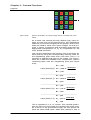
The Bayer filter’s smallest unit consists of a 4 x 4 pixel
cluster. Two pixels have a green filter (because of the human eye's higher sensitivity for green), one pixel has a red
filter and one pixel has a blue filter (see Figure 3.20).
Therefore each pixel detects a light value that can be attributed to a single color. Consequently, three spatially
displaced color images are obtained, of which the green
image has twice the resolution when compared to the
blue or the red image.
User Manual pco.camera status 12/2004
Chapter 3 Camera Functions
page 26
Figure 3.20:
p00
p01
p02
p03
green
red
green
red
p10
p11
p12
p13
blue
green
blue
green
p20
p21
p22
p23
green
red
green
red
p30
p31
p32
p33
blue
green
blue
green
Section illustration of a CCD image sensor covered with color
filters.
As a result, this camera primarily detects gray value images, if it has color CCD image sensors. The applications
software converts the images (via the position of the color
filter) into RGB or other color space images. For this purpose, a variety of solutions and algorithms exist that use
appropriate interpolations to try to compensate for the
lower spatial resolution.
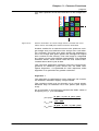
The camera replenishes the missing color information for
each pixel by using the corresponding intensity value for
the neighboring pixel within their color filter. This 2 x 2
operator is applied pixel-wise to the image. The instructions are to take the available color components, without
combining them with the neighboring pixel (see Figure
3.20):
R00 = p01
color pixel (0,0): G00 = p00 or
(p00+p11)
2
B00 = p10
____________________________________
R01 = p01
color pixel (0,1): G01 = p00 or
(p00+p11)
2
B01 = p10
____________________________________
R10 = p01
color pixel (1,0): G10 = p11 or
(p00+p11)
2
B10 = p10
____________________________________
R11 = p01
color pixel (1,1): G11 = p11 or
(p00+p11)
2
B11 = p10
This is repeated in a 2 x 2 cluster. This method quadruples the blue and red pixels and doubles the green ones.
As a result, in the processed image, the four pixels will
have the same RGB value. While this method is fast, it
User Manual pco.camera status 12/2004
Chapter 3 Camera Functions
page 27
only has a quarter of the real resolution of the image sensor.
R00
p00
G00
B00
green
Figure 3.21:
R01
p01
G01
B
red
01
p02
p03
green
red
R10
p10
G10
B10
blue
p11
p12
p13
green
blue
green
p20
p21
p22
p23
green
red
green
red
p30
p31
p32
p33
blue
green
blue
green
Section illustration of a CCD image sensor covered with color
filters where the RGB pixel values should be evaluated.
Another method is to treat the same color pixels as a single image array and shift the color arrays onto one other.
For example, red, blue and green pixels are adjusted to
form one image (the green pixels are averaged to adjust
their number to the others). Then the image is magnified
by a factor of two using bilinear interpolation. This method
achieves better visual results than the first method discussed above and is just as fast.
The camware application software uses two improved algorithms to transform pixel values into the RGB color
space. Algorithm 1 is optimized for color response, while
algorithm 2 is optimized for greater resolution.
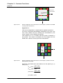
Algorithm 1
This algorithm is optimized for color response. As a result,
its resolution has been slightly compromised.
The resulting pixels may be thought of as virtual pixels,
because they lie between four real pixels (see Figure
3.22).
As an example, in the following section the RGB- value of
the pixel pRGB (1, 1) is calculated:
pRe d (1, 1) =
( 9 ⋅ p21 + 3 ⋅ p01 + 3 ⋅ p23 + p03 )
pGreen (1, 1) =
pBlue (1, 1) =
User Manual pco.camera status 12/2004
( p11 + p22)
16
2
( 9 ⋅ p12 + 3 ⋅ p10 + 3 ⋅ p32 + p30 )
16
Chapter 3 Camera Functions
page 28
p00
p01
p02
p03
green
red
green
red
p10
p11
p12
p13
blue
p20
Figure 3.22:
green
pRGBblue
(1,1)
real pixel
green
p21
p22
p23
green
red
green
red
p30
p31
p32
p33
blue
green
blue
green
virtual pixel
Section diagram of a CCD sensor with a Bayer- pattern and RGB
virtual pixel calculations.
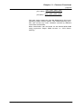
Algorithm 2
The second algorithm is optimized for spatial resolution.
For every real pixel that already represents one color, the
two color values that are missing are calculated by the
mean values of the neighboring pixels.
This results in a 3 x 3 matrix with the pixel of interest in
the center. The matrix is shifted over the image and the
RGB color values for each pixel are calculated.
Figure 3.23:
p00
p01
p02
p03
green
red
green
red
p10
p
p00
RGB
p12
p13
blue
(1,1)
green
blue
green
p20
pp10
RGB
p22
p23
green
(2,1)
blue
green
red
p30
p31
p32
p33
blue
green
blue
green
Section diagram of a CCD sensor with a Bayer- pattern and the
RGB pixels calculated.
Example: The RGB value calculations for the pixels p (1,1)
and p (2,1):
pRe d (1, 1) =
( p01 + p21)
2
pGreen (1, 1) = p11
pBlue (1, 1) =
( p10 + p12)
pRe d (2, 1) = p21
User Manual pco.camera status 12/2004
2
Chapter 3 Camera Functions
page 29
pGreen (2, 1) =
pBlue (2, 1) =
( p11 + p20 + p22 + p31)
4
( p10 + p12 + p30 + p32)
4
This new color image can now be displayed in the corresponding RGB-Lookup-Tables. The white balancing function can correct any color variation caused by different
color filter sensitivities.
More information can be found on the World Wide Web
using keywords "Bayer RGB convert" or "CFA demosaicing“.
User Manual pco.camera status 12/2004
Chapter 4 Data Interfaces
page 30
4
Data Interfaces
The pco.camera system is delivered with three interface
options: Firewire 400 (IEEE1394a), Camera Link or Gigabit
Ethernet. To determine which interface is implemented,
please see the technical datasheet in the appendix of this
manual.
These interfaces transfer images from the camera to the
computer as well as send command and control sequences and read status information from the camera. In
standard applications, the interfaces act like a “point to
point” connection from the camera to the PC. As the
cameras are intelligent and have a self-operating software
system, they can collect and record images without an interface connection.
Control commands are sent asynchronously and status
information is sent periodically (every 500ms or after each
collection of an image). A detailed description of the
communication between the camera and the PC is located in the software development kit (SDK) manual
which is available free of charge.
4.1
Interface Structure
While it is running on the PC, application software can
send the camera commands and request status information at any time. Image data can also be received and
processed. The dynamic link library (DLL) connects the
application software with the driver layers (see Figure 4.1).
pco.camera - layer structure of commands
PC - application
PC - DLL (adaptation to interface driver)
PC - driver layer(s)
hardware - data transmission
pco.camera - communication port
pco.camera - COC processor
Figure 4.1:
pco.camera - FPGA
Command structure layer model used with the pco.camera
system.
The commands that are sent to the driver are valid for all
pco.camera systems and for all interface types. The driver
converts these commands into hardware-related instructions to communicate with the various hardware ports
such as COC-processor (Camera Operation Code) or the
installed FPGA controllers (see Figure 4.1).
In Figure 4.2 the Firewire400-interface structure is shown
in detail.
From top to bottom: The pco.camera application software
accesses the camera-API, which represents an independent layer from the data interfaces. In this example, the
User Manual pco.camera status 12/2004
Chapter 4 Data Interfaces
page 31
camera-API, itself, distinguishes between the different interfaces and accesses the IEEE1394 driver-stack. This
stack uses an asynchronous serial data channel for the
command and status information in both directions and
an isochronous channel to transfer the image data from
the camera. The various channels are connected inside
the camera to the dedicated hardware, such as Camera
Operation Code – processor and controller FPGAs.
commands, status
Figure 4.2:
4.2
image data
Firewire 400 example of the command structure layer model
used with the pco.camera systems.
Firewire 400
Firewire400 (IEEE 1394a) is a serial Bus- system with a
400 Mb/s bandwidth. Up to 63 cameras can be connected on one bus. The maximum (guaranteed) transfer
speed over the isochronous channel is 32 MB/s.
The standard cable length is 1.5-4.5 m. Longer cables,
ranging from 10-20 m are possible within the specification
of IEEE 1394a and are available on request. The
pco.camera system is fully compatible with the Firewire
so hubs to stretch the distance between the camera and
the computer work well (two hubs with 10 m cables result
in a working distance of 30 m). Optical repeaters are recommended for longer distances. These devices are available upon request and provide a working distance of several hundred meters. The standard connector is the standard connector used in pco.cameras is a six-pin Firewire
connector.
OEM and system integrator information:
The Firewire hardware (OHCI) has a standardized software interface, but it does not include the implementation
of APIs or camera functions like DCAM. Detailed information can be found on:
•
http://www.1394ta.org/
•
http://www.apple.com/de/firewire/
•
http://www.1394la.com/
•
http://www.linux1394.org/
User Manual pco.camera status 12/2004
Chapter 4 Data Interfaces
page 32
•
4.3
http://www.firewire-1394.com/
Camera Link
Camera link is a point-to-point connection with a 200 –
1000 Mb/s bandwidth. The pco.cameras use the “base –
configuration” (1 cable) which gives a transfer speed of
200 Mb/s at 66 MHz and 255 Mb/s at 85 MHz. The clock
rate is selectable with camera commands. There is no defined standard software (API). Updated information can be
found at:
4.4
•
http://www.machinevisiononline.org/public/articles/in
dex.cfm?cat=129
•
http://www.datatranslation.com/solution_center_imag
ing/Camera-Link.pdf
•
http://www.nortechsys.com/intercon/camlinkart.shtml
Gigabit Ethernet
Gigabit-Ethernet is a Peer-to-Peer architecture. If only a
camera is connected with a PC and the usual transfer
protocol TCP/IP is not used, then this connection is reduced to point-to point. The advantage is to use the Gigabit-Ethernet’s sophisticated physical transport medium
with a 100 Mb/s maximum transfer speed. The cables can
be up to 100m long with simple CAT5 and even longer
with optical units. Until now, a camera-specific software
standard did not exist, although many proposals from
several groups are being discussed. Further information
can be found at:
•
http://www.10gea.org/
•
http://www.pleora.net/GigE/
User Manual pco.camera status 12/2004
Chapter 5 Software
page 33
5
Software
A CD with applications software and manuals is included
in this package. Specific versions and updates are available for download at our web site: www.pco.de.
5.1
pco.camware
Camware applications software provides complete control of all camera types as well as extensive data recording possibilities.
Detailed information for camware is included in the online
help or in the attached "pdf" manual. The newest versions
are offered on our web sites (http://www.pco.de) at no
charge.
5.2
Software Development Kit (SDK)
A free software development kit is available to allow programmers to easily integrate camera control software into
their applications programs. A version for Windows XP is
included in the CD-ROM. For updated versions, please
visit our website at: (http://www.pco.de).
5.3
Drivers
A Twain Driver and a Firewire 400 driver for Windows XP
are available for pco.cameras integration.
These drivers are located on the CD. The most recent
versions
can
be
obtained
on
our
website
(http://www.pco.de).
Additional software and drivers not listed here can be
obtained on our web site (http://www.pco.de).
5.4
Third Party Software Drivers
Plug-Ins or corresponding drivers are available (or
planned) at no charge for the following image processing
and analysis software packages:
•
Image-Pro Plus, version 3.0 or higher (Media Cybernetics)
•
MetaMorph / MetaFluor Software (Universal Imaging)
•
LabView (National Instruments)
•
AxioVision (Carl Zeiss)
•
LabView (National Instruments)
•
Matlab (Mathworks)
•
ImageJ (NIH)
Detailed information about drivers or Plug-Ins can be
found on our web site (www.pco.de/support) or by contacting our sales team.
User Manual pco.camera status 12/2004
Chapter 5 Software
page 34
5.5
Firmware Update
The pco.camera system can easily be firmware updated
by the user. It is done over the existing interface, with no
special cables or other equipment needed. The update is
done via the special programmer software, which is included in the firmware update zip-file package. This software is located on the CD or can be downloaded from our
web site.
User Manual pco.camera status 12/2004
Chapter 6 Service and Maintenance
page 35
6
Service and Maintenance
6.1
Service
The camera is designed to be maintenance-free with no
adjustments or inspections needed.
6.2
Camera Maintenance
Unplug the camera from any power supply before cleaning
it.
Use a soft, dry cloth for cleaning the camera. Do not use
liquid cleaners or sprays.
6.2.1
Cleaning the Lens
Do not use a dry cloth to clean the lens and never use
aggressive liquids or materials.
The lens is best cleaned with pressurized air or with liquid
cleaners such as pure alcohol or with special optical
cleaners that are available at high quality photo stores.
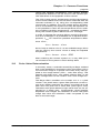
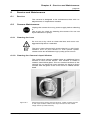
6.2.2 Cleaning the Camera’s Input Window
The cooled pco.camera models have an additional input
window in front of the sensor. This window is made of
coated, fused silica glass. The non-cooled versions of the
camera do not have this input window so there is direct
contact with the glass cover of the CCD or CMOS sensor
itself.
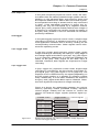
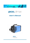
Figure 6.1:
Camera housing shown without the lens. There is direct access
to the input window. Behind this input window is the visible
image sensor (cooled version).
User Manual pco.camera status 12/2004
Chapter 6 Service and Maintenance
page 36
Every time the input window is cleaned, there is the possibility of surface damage. Do not clean the input window
unless it is absolutely necessary. Be careful and avoid
scratches and damage to the input window surface.
Do not use a dry cloth to clean the input window.
Before using specialized optical cleaning liquids, first
blow away any particles on the surface with pressurized
dry air. Cans of pressurized air are available at photo and
computer stores for cleaning optical devices. If additional
cleaning is necessary, use suitable liquid cleaners.
Liquid cleaners for optical devices are either pure alcohol
or special optical cleaners, available in high quality photo
stores.
Never use aggressive cleaning liquids such as gasoline,
acetone, spirits or nitro cleanser. These liquids may damage the input window surface.
Use a cotton swab dipped in pure alcohol or optical
cleaning liquid and wipe only on the glass surface. Do
not get any cleaning liquid on the metallic parts such as
the lens thread, because tiny detached particles may
scratch the surface.
Always store the camera with the protective cap or with a
lens mounted to avoid dust and dirt on the input window.
User Manual pco.camera status 12/2004
Chapter 7 Appendix
page 37
7
Appendix
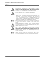
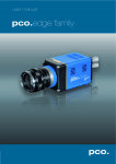
7.1
Camera - Mechanical Dimensions
Camera - front view
C-Mount
F-Mount
User Manual pco.camera status 12/2004
Chapter 7 Appendix
page 38
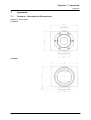
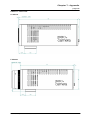
Camera - rear view
Firewire (IEEE1394)
Camera Link
User Manual pco.camera status 12/2004
Chapter 7 Appendix
page 39
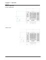
Camera - side view
C-Mount
F-Mount
User Manual pco.camera status 12/2004
Chapter 7 Appendix
page 40
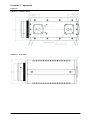
Camera - bottom view
Camera - top view
User Manual pco.camera status 12/2004
Chapter 7 Appendix
page 41
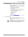
7.2
Customer Service
If you have a question, which is not adequately addressed
in this manual, please contact PCO or your local dealer
(addresses on page 2).
To speed your request, we need the following information:
•
Short description of the problem
•
Description of your application
•
Camera settings
•
Type and version of camera software being used
•
Camera serial number (located on the silver label on
the bottom of the camera)
•
Power supply serial number (pco.power)
•
Operating system (PC)
•
Processor type (PC)
•
Memory
•
Graphic card
•
Graphic card setup
At the web site www.pco.de/support there is an information form to fill out and send by email.
7.3
Trouble Shooting
In case of a damage or malfunction, send the camera with
the above information to PCO for repair.
Before sending the camera for repair, first, contact your
local dealer.
When shipping the camera for repair, be certain to carefully pack the camera with proper shipping materials. If
possible use the original packaging. Use the protection
cap to protect the camera on the lens thread.
User Manual pco.camera status 12/2004
Chapter 7 Appendix
page 42
7.4
Camera Disposal
The camera includes electronic devices, which can contain materials harmful to the environment. If the camera is
to be discarded, please dispose of it in an environmentally
responsible manner and use recycling facilities, where available.
User Manual pco.camera status 12/2004
Dear Customer,
We hope this camera will be an always valuable tool for your scientific day in, day
out work.
Comments, suggestions or any new idea on our system are welcome.
We are at your disposal at any time, also after your buying of this camera.
Your PCO Team
pco.
imaging
PCO AG
Donaupark 11
D-93309 Kelheim
fon: +49 (0)9441 2005 0
fax: +49 (0)9441 2005 20
eMail: info@pco.de
www.pco.de