1
Winegard/Acer Phase III Triple LNB Dish
The following installation manual for the Winegard/Acer Phase III Triple LNB dish is
brought to you by the SolidSignal.com Tech Team. For more information about this
product and its availability, please click on this page or visit our web site at
www.SolidSignal.com.
Email: info@solidsignal.com
I
,
~
Introduction
Safety Information
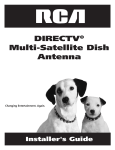
Your DIRECTV Multi-Satellite
Dish antenna is designed for use
Local building
with up to four independently
operating DIRECTV Receivers,
antenna and the coaxial cables to be connected to a
and electrical
Along with your receiver User Manual, this guide will provide
grounding
the information you'll need to successfully install and operate
damage the equipment
your DIRECTV System. Throughout the manual, the DIRECTV
injury or death to you. For your own safety, follow these
Multi-Satellite
Dish antenna will be referred to as the "antenna,"
important
electrician
For best results, we suggest you read carefully through these
pages first before beginning installation.
for an individual
described,
The guide is intended
.If
experienced in performing the various tasks
electrical
.Determining
U .
.Do
safe working practices around heights and
.11 t
rl
.Watch
sure there are no people, pets, etc. below when you
out for power lines which may be overhead,
of them with ladders, antenna and tools during installation
wall,
The Federal Communications Commission (FCC) has ruled
that a local government or homeowner's association may not
lifting and securing the 20-lb. antenna assembly
.Grounding
as possible on the ground
underground and/or hidden behind walls, keeping safely clear
d .11 h I . t
h
0 rl
0 es In 0 your ouse
.Routing
coaxial cable(s) through foundation,
d fl
tt .'
t .
II
un er- oor, a IC or In erlor wa s
.Safely
as many functions
are working on the roof
if there are water pipes, gas lines or wiring
d
or dangerous to view the attached bubble
not install the antenna on a rainy, snowy or windy day
.Make
hazards
a power
in your area for assistance:
you will be mounting your antenna in a location where it
.Perform
hidden near where you may drill
.sing
as well as cause
instead. DO NOT risk falling
an antenna location with a good southerly
a ladder and working on your roof
.Observing
or the building,
may seriously
level (see page 6), use a small mirror or plumbing level
view of the satellites
.Climbing
Improper installation
safety rules or contact a licensed inspector or
will be difficult
including:
.Determining
electrode.
codes (NEC) require the
prevent the installation of satellite antennas one meter or
the antenna and cable(s) as recommended
in the National Electric Code (NEC)*
NOTE: If you don't feel completely comfortable with these
sma"er in diameter, unless legitimate safety restrictions such
.'
as fire codes are in effect. Call FCC tel: (202) 418-0163;
FCC Web sites at http://www.fcc.gov/cgb/satellite.htmi or
http://www.fcc.gov/mb/facts/otard.htmi for more information.
tasks, simply contact the store where you purchased the
system for information on having your system installed by
a local authorized DIRECTV installer,
DIRECTV~programming is sold separately. To activate DIRECTV
programming, please call 1-800-DIRECTV(1-800-347-3288).
More programming information is also available at DIRECTV.com.
Activation of programmingmay be subject to credit approval and
requires valid service address, social security number and/or
major credit card. Depositor prepaymentmay be required. In
some areas, programming may be provided by members or
affiliates of the National Rural Telecommunications Cooperative.
*NECis published
bythe NationalFireProtection
Association,
1 Batterymarch
Park,
Quincy,Massachusetts.
02269-9101
andmaybeavailableatyourlocalpubliclibrary.
.: ~ rj.. '[ ~
...1
DIRECTV
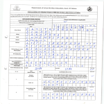
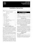
Multi-Satellite
DishAntenna
.""~--
,-
I-
~!!!~B("""""]1;~;PJ~
\~~~t4':::~
~ --"
~---i
Cj~~~EJ
C5:=E~
IISB
--i-\-:-;:>
J_!Dish Mounting Hardware
Multi-Satellite Dish Reflector
LNB Arm/Antenna Back Assembly
raraiW
eeee
@
Triple-head, Multi-Satellite
@
LNB Mounting Hardware
LNB with built-in Multi-Switch for
four Independent Outputs
ffrc:«llj
~--
I
W
e e
Grounding Screw
i
(~
EZAUGNTMMast
ToolsRequired
I
Stepsfor Installation
7/16" Nut Driver
In the following pages, you'll find step-by-step instructions for:
[==~Jr:[J=:::=O
Adjustable Wrench
(Q~~~~~~~:~5J
Screwdriver (Phillips)
c===n:o:::=~
Magnetic Compass
G)
~ :if
-
m
8
Determining Coordinatesfor Aiming Antenna
page 4
0
Finding Suitable Antenna Site
page 5
8
Installin~ EZA~IGNTMMast
page 6
G
Assembling/Adjusting Antenna on Ground
page 7
8
Attaching Antenna to Mast
page 7
0
Routing RG 6 Cable(s)
page 8
0
Grounding Cable and Antenna
page 8
0
Attaching LNB to Antenna
page 9
0
Aiming and Fine-tuning Antenna
page 9
s
EI t .
ec rlc
d B' t
rl an
I
D ' II
I/'/'
/' /' /' /' /' /' /' /' /' /,)
InformationAlso Included:
Troubleshooting Check List for Initial Installation
page 11
Loss of Signal/Rain Fade
page 12
Installation with Long Cable Run
page 12
OptionalAccessories(not
included)
Typical installation kits (sold separately) include:
.Mast base mounting hardware
.RG 6 coaxial cable(s) with F connectors
.Grounding
.6"
hardware, grounding wire, wire clips, etc.
plumbing level
DIRECTV
Multi-SatelliteDishAntenna
3
I--l
r -:0-1
.
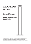
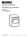
DeterminingCoordinates
for Aiming Antenna
The coordinates (Azimuth, Elevation and 1ilt numbers) are
based on your ZIP code and can be determined easily by using
your receiver. You will need these numbers for site survey and
antenna adjustments.
NOTE:The antenna does not need to be installed for this step.
Connectyour receiver to the TV
--the
~Io
~
====
: ; ~~S(-!
I~~
Depending
onyourreceiver
Navigate to the antenna installation screen menu. Select
installation as an "oval 3-sat" (some receiver brands may call
~odel,yourdisplaymaylcx:k
different
fromshown.In this
it: "tri ple" ' "3 sat location" "."Sat 123"
,
example,
a Southern
California
ZIPcode"92683"is entered.
andreceiveroutputs:
.Azimuth:152
.Elevation:50
.lilt: 102
Findyour coordinates
Azimuth
(horizontal,
side-side) \~==~/
Elevation //---~"\
(vertical,
up/down)
lilt
(dishreflectorrotation)
0
Consulting your receiver manual, connect the receiver'svideo
or Channel 3/4 outputs to the corresponding TV input. Turn on
TV and the receiver.
Setthe antennatype
I-;=~==:::\
or "Sat ABC").
, ,
..
Navigateto the antenna-pointing menu screen. Enter your ZIP
code, then write down the numbers in space provided below.
YourAzimuth
YourElevation
Yourlilt
I
~
~
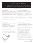
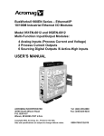
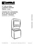
Finding Suitable
~
Ant
en
n a
Sit
I~
e
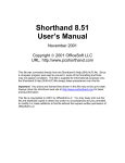
If you liveon the WestCoast,the If you live on the EastCoast,the
satelliteswill be to the south-southeast. satelliteswill be to thesouthwest.
("...~
~"'~~,
~1800
NOTE:It's important to estimate the cable length at this point.
.ru270'
The DIRECTVsatellites are located in the southern sky above
the Equator. The location for your antenna must have
elevation-angle clearance (abovethe horizon) and 18° span
clearance (from 101° to 119°) for an unobstructed view to all
three satellite locations. Northern border states haveelevation
.
30° d
h
b d
t t
d 60°
SatC,1100with
readings toward
an sout ern or er s a es towar
.Converted
Transponders
( ~O~
with a new Multi-Satellite Dish Antenna,
be sure to check for the required 18°
clearance. If you do not have the
required clearance, you should use
r
~'--:::--~~71'
A suitable antenna site requires an unobstructed view of the
southern sky, a stable antenna mounting surface, a distance of
100-ft or less for RG 6 cable from your antenna to your
receiver, and grounding nearby.
NOTE:If you are replacing an 18" dish
.
2
#8, #10,#12
SatA, 1010with
Transponders.c::~~
#lto#32
a different location.
"=:~=:7
""
",
"
""
"
~=:~:;=7
--',',
,
",
,
'
"'"
"
""
",
SatB, 1190with
Transponders
#22 to #32
"
,
",
','
" 18°-','"
',,'
,
','"
"
~
No trees,leaves,
buildingscan bein theline-of-sight
@
between
antennaandsatellites.
Duetothe manyconfigurations
possible,
mast-mounting
hardware
isnot included.
Besureyouhavethenecessary
mounting
hardware
beforeyou begin.
Optionalmountingkitsareavailable
atyourlocalelectronics
store.Belowarepotentialmounting
sites.
StuccoExteriorWall
Wooden
Rail
Chimney
Ground
DIRECTV
Multi-SatelliteDishAntenna
5
I
Viewofbubble;:gOntoPofmast
@()
I)
Installing
EZAllGNTM
Mast
-
~
~
@
Now"you're
ready
toin~tall
theantenna,
ma~t
atthe
\~)
\~)
~
location you've chosen In Step 2 and align It to be plumb
Right
(perfectly
0
the Multi-Satellite
@
_)
~-
straight up). Plumbing
the mast is critical
Dish antenna to receive optimal
for
signals,
and failure to align it properly will result in difficulty
acquiring signals as well as a greater tendency for signal
outages in adverse weather.
Mount the base securely
The mast base must be sturdy so antenna does not shift under
Side viewof bubble level in the mast
Wrong
Wrong
PI
various weather conditions and its own weight. Mounting is
preferable on wood or masonry. Unsuitable sites may be
WTJrI
I '='
Right
I
P==Tl
handrail, aluminum or vinyl siding, composite paneling, and
I~I
fiber/particle/strand
"-
Mak
th b bble I I ti
'
t
t '
fed
I b
'
e sure e u
jeve rame In IICmas IS sea prope~'Y orpressing
down flat on it so the lip of the frame sits snuglyon the top edgeof the mast.
boards.
CAUTION!When installing mast base, avoid placing finger
,
'
between mast bottom and base to prevent bel ng pi nched or cut.
Align the mast
.The EZALIGN Mast pivots up and down, and from side to
."
side. A bubble level IS located In the top of the mast to
Lookingdown into mast
The patentedmast has two slotsat the the bottomthat allowit to move up
and down and side to side. Thisaids the centeringthe bubble level even
when the mast baseis mountedon an unevensurface.
assist in al ignment.
.Loosen
,
the four mast bolts slightly. Then move the mast
up/down or twist side-to-side until the bubble in the bubble
level is centered as shown at left.
CAUTION! If the mast is mounted in a location where it is
difficult
or dangerous to view the bubble level, use a small
mirror or plumbing
level instead. DO NOT reach out and risk
falling from roof or other high place.
Tighten mast bolts
When mast is straight up (plumbed),
.I;"""""~
~~~""""
,-,
,\
"
with your other hand. Make sure bolts are secure. You may
, ",
,,
want to tighten further with an adjustable wrench.
,,/
Tighten
(two on
Up and DownMovement
0
and while still keeping
hold of the mast, tighten the four bolts with a 7/16" nut driver
Side to SideMovement
.Ass
~
e m b I i n g/ Ad jus
Antenna
on
tin
g
I
Dishattachingto theLNBArm/Antenna
BackAssembly
.
Ground
On even ground, attach dish to the LNB Arm/Antenna Back
Assembly as shown. Leave off the Triple-head LNB until the
antenna is mounted on the mast and you've routed cable
through the LNB Arm.
Set Tilt Adjustment
""
cQ.
.At the back of the antenna assembly, loosenthe Tilt nuts
and then set the Tilt adjustment according to the coordinate
number you obtained in Step 1.
.Tighten the Tilt nuts. Do not change the 77ftadjustment
again from this point on (even if you could not find the
satellite signal during alignment). Unlike the Elevation and
A zlmut
.
h coor d ...the
Inates, there IS no need to fine-tune Tilt;
~---~
In thisexamplewehave
forSouthern
California
(ZIPcode~268:3)'."
7i/tsettIngIS 102 .'
,
I
doing so may cause alignment difficulty. For some of the
Eastern Seaboard states, however,there maybe an
exception: see Step 9, note #2, on page 10.
~
,
"
7i/tNuts
.1
,oneshownl
Set Elevation Adjustment
.At the side of the antenna assembly, loosen the two Elevation
nuts (one on each side) and preliminarily set the Elevation
adjustment, per the coordinate number obtained in Step 1.
.Tighten the Elevation nuts, but not completely. This
is a preliminary adjustment which you may have to
.'
fine-tune later on.
--~
In thisexamplewe show
;".7
for Southern
California
.::/
/
(ZIPcode92683),the
I
Elevation
settingis SO'
,
(usethepositionof the
metaledgeto theElevation
scale;do not usethewasher
or theboltasreference).
,
e
Attaching
.Slide
Antenna
to
Metaledge
at SO'
~""
'
"
"
I
;
I
I
~---~
Mast
Elevation
Nuts,
oneon eachside
Azimuth!
tClampBolts
the back of the antenna assembly onto the top of the
mast until it stops at the pivot bolt. If necessary,slightly
loosen the two Azimuth/Mast clamp bolts and pivot bolt so
the antenna will go on to the mast.
.Tighten the two Azimuth/Mast clamp bolts and the pivot
bolt just enough so the antenna has only side-to-side
movement (rotational swing around the mast) for later
Azimuth alignment in Step 9.
;,'
,"",
-'"',,
,,
,1
,
1
:
)
--',
"
"I
",
",
"-PivotBolt
DIRECTV
Multi-SatelliteDishAntenna
7
e
roun Ing
Block
", -
~
\
,,'
,
~JJc1' ~
I
I
~
ToReceiver
'
-_
",
.\
1
Beforestarting, inspect the inside of each cable connector for
foreign materials and/or short. Make sure that the copper center
.)
conductor is straight and centered in the connector.
,
,
Runcable from receiver
I
'
0- :
Verify that there are no wires or pipes blocking the location
where you want to feed the coaxial cables into your home. Drill
a 1/2" inch hole for each cable. Connect cable to the "Sat In"
jack on the back of your receiver. To preventshort, leave
receiver unpluggeduntil Step 9.
:,
'-.
I "
WaterDrip ,
Loop
You'll route RG 6 cable from your receiverto the cable grounding
block, then from the grounding block to the triple-head LNB.
I
Ca
d?le
G
RoutingRG6 Cable(s}
,,'
...'
,"",~
"'"
-
.
I
ToAntenna
Connectto groundingblock
_I'~IE
Mount the grounding block close to the point of cable entry
into the house. Connectcable to grounding block as shown.
Dualgroundingblock,onereceiverhookupshown
rounding.
,"
Option
#1
~
--'
Wire
from ~../
Grounding
Antenna '
"
I
,
,'1_BJ~1s__-["
---'
,
')
~
~'
the satellite receiver system and other components from
lightning damage.
oint
.Ground wire can be attached anywhere on the metal part of
the antenna, but there is a convenient grounding screw at
,-
o 'A"
roun Ing..Ire
,, from
Antenna
G
d
,,
0
I
I
I
~
,,
,,
Cold
water
pipeonly/
,
>
,
Grounding
Wirefrom
CableGrounding
Block
,
I
I
I
---'I
,,
, ...
,'
(8)
grounded metallic service raceway,grounded electric service
_"~
",
.,.-
I
I
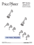
Grounding the antenna and cable grounding block help protect
.Grounding point can be outside metal cold water pipe at
point of entry (no gas or hot water pipes), 8-foot ground rod,
-'
...' --,
Antenna
250 and 810).
.
Usegrounding
wires#10copperor #8 aluminum
Option #2
and
one side of the mast base. Installation should comply with
local codes and the National Electric Code (NEC,Sections
--~'Grounding,
Wirefrom'
'Cable
I 0'
" Grounding "
,
>
Coldwater
pipeonly
, ", "
,,'"
Cable
,,
,
I
,:
Grounding
,,
equip enclosure, etc. Option#1: Both ground wires go to
the same ground point. If the two grounding points are
different, a #6 copper wire should be connected between
them. Option#2: The dish antenna grounding wire goesto
grounding block first, then to the grounding point.
I.
J
e
Attaching
LNB to Antenna
I
SatB,SatC,
.
1190 1100 SatA,
The triple-head
LNB has four identical outputs, each
1010
supporting one independently operating receiver. To simplify
future installation
of additional
,
,
receiver(s), you may want to:'
route
more for
cables
to the
antenna at
thisalignment.
point. Only one cable:
is needed
antenna
fine-tuning
and
',\:'
\,,---~
!
:
\
.RG 6 cable from the grounding block can now be routed to
"
the LNB on your antenna. Attach the triple-head LNB onto
the LNB Arm and fasten with included mounting hardware
(Philip screws and nuts). Dress cable with enclosed tie
wraps, allowing for cable water drip loop if necessary.
~
Aiming
~
Fine-tuning Antenna
'
I
\\
'
,
"
""""
"
~~ '
~
upcabJ,
es,one
I
sown
h ) to the LNBand
H00
kIng
"
acing
Ita h
the LNB
toAntenna
-up tofourcables
canbeconnected
thisway.
"
and
When you fine-tune the antenna to one satellite, the other two
satellites should be aligned automatically.
"
Plug in and turn on
your receiver.
.Use
Align
the
Azimuth
the on-screen signal strength meter to fine-tune the
[ ::J~J
.0
antenna. It is important to obtain the strongest signal
possible; the higher the signal strength, the less likely you
are to experience signal outages during adverse weather.
.With
a cell phone and house phone, ask someone to relay
signal strength values to you, or hook-up a portable TV at the
installation site. Your receiver may be equipped with an
audible beep tone feature; the higher pitch, the higher the
signal. A hand-held signal meter is also an option.
Align the Azimuth
.Set your on-screen menu to the signal meter mode, on
=
~I.
~
"..
~
Satellite
A (1010).
a transponder
that is unique
to
Sat A (such
as 1 -6,Use16)
for your alignment.
Point the
antenna to a generally southerly direction,
I~=
~
..,
:~:
...:
or use the
::.~:
Azimuth number obtained in Step 1 and a compass for
a more precise starting point.
.Very
slowly rotating the antenna around the mast a few
degrees at a time, pause 3 -5 seconds in between for signal
strength meter update. You should be able to find the
satellite signal first and then the signal peak, indicated on
your screen. Once you sweep through the peak-signal point
"
I
"
I
on the screen, stop. You may want to swing past the peak
point a couple of times to make sure.
.Mark
the mast and antenna bracket point with a pencil.
I
:
','
Pencil Marks'
:
",
"
"
'-- -- "
,
DIRECTV
Multi-SatelliteDishAntenna
9
I
Verify
Azimuth
alignment
-
Switch to Sat B (119°) on your on-screen menu, using
J
Transponders 23, 25, 29 or 31. Verify that signal is also
peaked at 119° by very slightly rotating the antenna around
\
~:~/
the penciled marking on the mast. Once satisfied, tighten the
two Azimuth/Mast clamp bolts.
[
~EI
NOTE: Sat B (119°) signal strength may read different than
Sat A (101°) signal strength, depending on the satellite
transmission patterns in the area. You only need to see
.0
VerifyAzimuth
whether Sat B (119°)
Alignment
is peaked and not try to compare
signal strength numbers. It's OK to be close but not at the
peaks for both locations simultaneously.
Fine-tune
theElevation
Use Sat B (119°) or Sat A (101°) on-screen signal meter. While
holding the LNB Arm, slightly loosen the two Elevation nuts.
~
=
I0
,. ...;,
~
I~
=
Move it up/down slightly and observe the signal strength on the
screen. Find the peak and tighten the two Elevation nuts.
.6
Verify
satellite
signals
~~:
Confirm the final signal-peak readings at all three satellite
..locations.
Sat C (110°, Transponders 8,10
and 12.) should
be aligned automatically.
NOTE 1: Occasionally, you may see a transponder
(101°),
/
--~\
Sat B (119°) or Sat C (110°)
possible that this transponder
programming
is reserved for upcoming
expansion. Switch to other transpo~ders
same satellite
at the
location to verify that you have good readings
and that your antenna alignment
Fine-tunethe
at Sat A
not active, it is
is satisfactory.
NOTE2: In most of the U.S., the Tilt Adjustment should be
Elevation
fixed. However, because of large Tilt angle to 119° satellite in
Eastern Seaboard states, a small amount of Tilt fine-tuning
adjustment may improve 119° signal strength without
significantly
changing 101° signal reading. For these states,
the following Tilt fine-tuning
procedures are recommended:
1. Follow alignment procedures from Step 1 through Step 9;
tighten Elevation and Mast clamp bolts.
2. Fine-tune Tilt Adjustment
first by +3 degrees and then
-3 degrees. Tilt is optimized
--signal
~
10
~
.,"...'
I~
...optimized
'B"
i~g
@
when you see the 1010
reading essentially unchanged and 119° signal
strength improved by several points. Set Tilt to the
point and tighten
Tilt nuts.
I
Troubleshooting
CheckListfor Initial Installation
If the signal is not found, be sure the receiver user manual and the antenna installation
D
Make sure all cable connections are correct and each
connection
D
D
is seated/tightened
D
properly.
-
manual have been properly followed. Check to:
Your triple-head
LNB depends on the receiver to supply
power; the longer the cable length to the LNB, the greater
Inspect the inside of each cable connector for dirt or
the DC voltage drop. Your receiver depends on the antenna
to supply signal; the longer the cable length, the greater
possible connector to case/shield short.
the signal amplitude attenuation. Therefore, RG 6 cable
Verify the Azimuth,
length much longer than 100 feet (from each the receiver
to the antenna) should be avoided.
Elevation and 1ilt angles for your
location by ZIP code.
D
D
D
Make sure the 1ilt and Elevation pointers are aligned
RG 6 cable with solid copper center conductor is highly
recommended because it has much lower DC voltage drop
correctly to the scales. Do not use washer or bolt as
compared to RG 6 cable with a copper-coated, steel center
reference.
conductor.
Make sure the 1ilt adjustment is not changed from the
D
recommended setting for the antenna location.
D
The mast not being plumb/up
of alignment
D
RG 6 coaxial cable must be used.
Make sure the bubble level frame inside the mast is
seated properly, then check the mast alignment again.
straight
D
is a major cause
additional DC drops and signal amplitude
Remove existing TV-specific components,
attenuation.
to the basic
D
may not work with the satellite signal and they may be in
Make sure the satellite cable is connected to the "Sat In"
jack, not the "Antenna
In" jack. The "Antenna
the wall where you can't see them. When in doubt, run RG
at the back of the receiver is for off-air antenna
6 cable directly to your receiver.
cable TV input,
Make sure there are no obstructions
may
Remove such components, go back to the basic
connections called out in this manual and re-verify.
such as TV
connections called out in this guide. Such components
D
Some after-market, off-the-shelf add-on components
not be as advertised. They might not work or could cause
difficulty.
splitter, etc; reduce the installation
Standard RG 59 cable causes too much DC drop and
signal drop; it can not be used to pass the satellite signal.
(trees, buildings,
D
input or
In you live in a state on the Eastern Seaboard, you may
windows, corner or overhang of your roof, your body or
need to fine-tune your 1ilt Adjustment.
hands) -the
from NOTE 2, page 10,
signal does not pass leaves, branches,
In" jack
Follow directions
glass, etc, Also, keep in mind the 18° span clearance
to receive all three satellite locations. This required
D
D
If all are done correctly but the signal is still not found,
clearance may also mean you'll need to consider a new
change the Elevation adjustment
location when replacing an old 18" dish with this new
(:I: 2°, then :I: 4° from the called-for
Multi-Satellite
the procedure.
Drsh Antenna.
of the antenna slightly
setting) and repeat
Make sure the Access Card from your receiver is fully
inserted into the Access Card slot and oriented correctly.
DIRECTV
Multi-SatelliteDishAntenna
11
I
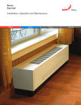
~
~
Fade
.The satellite signal may be lost temporarily due to
unusually heavy rainfall. An optimally aligned antenna,
along with the shortest possible cable run, minimizes
£=:~=:7
"'"
Loss of Signal/Rain
"
the chances of "rain fade."
.Make sure the antenna is mounted securely to prevent it
from being blown out of alignment in a heavywind.
[fI]~
--away
-~-
.Heavy snow accumulation on the LNB and the antenna may
reduce the satellite signal strength; snow should be swept
as soon as possible.
.Tree foliage growth into antenna's line-of-sight to the
satellite may result in gradual loss of picture.
Installation
/
/
with Long Cable Run
.For installations where the RG 6 cable runs from the
receiver(s)to the LNB far exceeds 100 feet (150 feet or
more), as encountered in a commercial or multi-dwelling
building, you need to use an AC power booster module to
bias the LNB.
.You will also need an additional RF signal amplifier to
compensate the signal amplitude loss. Otherwise,your
antenna and receiver may not work properly and be subject
to frequent outages in adverseweather. Contact a
professional concerning such installations.
@
7/29/02REV.1
@2(XJ2DIRECTV,
Inc. DIRECTV
and the CycloneDesignlogo,DIRECTV
PARATODOSand
EZALiGNare trademarksof DIRECTV,
Inc., a unit of HughesElectronicsCorporation.
07/0212~29ENG.0
~