1
IONIZATION SOLUTIONS
Digital AeroBar®
Ionization System
Model 5225S
User’s Manual
About Simco-Ion
Simco-Ion develops, manufactures, and markets system solutions
to manage electrostatic charge. As the world's largest provider of
electrostatics management products and services, Simco-Ion
improves its customers' business results by providing a total
solution to their electrostatic discharge and electromagnetic
interference challenges. Simco-Ion is a division of Illinois Tool
Works (ITW) with its Technology Group located in Alameda,
California. For more information about Simco-Ion visit www.simcoion.com or call 800-367-2452. Simco-Ion is ISO 9001 and ANSI
ESD S20.20 certified.
© 2012 Simco-Ion
19-5225S-M-01 Rev 2
Important Safety Information
Failure to follow these important safety cautions
could result in damage to Digital AeroBar System
components and voiding of your system warranty.
Use proper input voltage to avoid damaging the unit.
Never power-down an AeroBar by removing the cables, as
this can result in damage to the ionizer.
Do not clean emitter points while unit is powered. Doing so
may result in additional contamination and possible shock.
To avoid personal injury or damage to the equipment, perform
only the installation and maintenance procedures contained in
this manual.
Verify that the AeroBar is not powered before connecting or
removing cables. Failure to do so may result in damage to the
equipment.
19-5225S-M-01 Rev 2
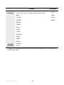
Contents
1 Description ......................................................................... 1
1.1 Overview ................................................................................................. 2
1.2 Remote Control....................................................................................... 5
1.3 Power Requirements .............................................................................. 7
2 Installation .......................................................................... 9
2.1 Mounting ................................................................................................ 11
2.2 Wiring..................................................................................................... 13
2.3 FMS Connection ................................................................................... 17
2.4 Daisy-chaining ....................................................................................... 17
3 Operation ......................................................................... 19
3.1 About AeroBar Adjustments.................................................................. 20
3.2 Using the Remote Control..................................................................... 21
3.3 Ionization Mode (OpMode) ................................................................... 25
3.4 Output Voltages .................................................................................... 27
3.5 On- and Off-times (Pulsed DC Mode Only) .......................................... 28
3.6 FMS Alarm Values ................................................................................ 29
3.7 Balance Adjustment and System Calibration......................................... 31
4 Maintenance ..................................................................... 39
4.1 Maintenance Power Down ....................................................................
4.2 AeroBar Maintenance ...........................................................................
4.3 Remote Control Maintenance ...............................................................
4.4 System Adjustment & Calibration .........................................................
40
41
45
46
5 Specifications................................................................... 48
5.1 AeroBar Model 5225S............................................................................ 49
5.2 Parts & Accessories............................................................................... 53
5.3 Dimensional Drawings ........................................................................... 53
6 Warranty & Service ........................................................... 56
19-5225S-M-01 Rev 2
1
Description
1.1 Overview
1.2 Remote Control
1.3 Power Requirements
19-5225S-M-01 Rev 2
1
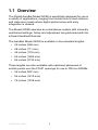
1.1 Overview
The Digital AeroBar Model 5225S is specifically designed for use in
a variety of applications, ranging from inside tools to work stations
and cleanroom areas where digital performance with easy
integration is desired.
The Model 5225S operates as a standalone system with internally
maintained settings. Setup and adjustment are performed with the
infrared Handheld Remote.
The AeroBar Model 5225S is available in five standard lengths:
• 22 inches (558 mm)
• 28 inches (711 mm)
• 44 inches (1118 mm)
• 64 inches (1626 mm)
• 84 inches (2134 mm)
Three lengths are also available with optimized placement of
emitter points over the FOUP openings for use in 300 mm EFEMs.
• 36 inches (907 mm)
• 56 inches (1412 mm)
• 76 inches (1918 mm)
19-5225S-M-01 Rev 2
2
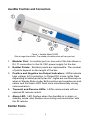
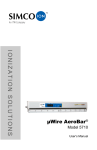
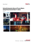
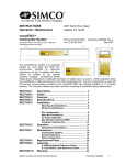
AeroBar Controls and Connectors
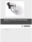
Figure 1. AeroBar Model 5225S
(Bar is longer than shown. The number of emitter points will vary per bar.)
1. Modular Port: A modular port on one end of the bar allows a
RJ-11 connection to the 24 VAC power supply for the bar.
2. Emitter Points: Emitters points are replaceable. The number
of points depend on the length of the bar.
3. Positive and Negative Ion Output Indicators: LEDs indicate
high voltage (HV) ionization. In Pulsed DC mode, lights flash
depending on which polarity has HV. Lights are continuously on
when in Steady State mode. Both positive and negative ion indicators and the Alarm LED flash once simultaneously during
communication.
4. Transmit and Receive LEDs: LEDs communicate with an
optional IR remote control.
5. Alarm LED: LED flashes when the AeroBar is in alarm or
standby mode; also flashes once during communication with
the IR remote.
Emitter Points
19-5225S-M-01 Rev 2
3
Emitter points are replaceable. The number of points depends on
the length of the bar.
Length of Bar in Inches
No. of Emitter Points
22
5
28
7
36 (2-load port configuration)
8
44
9
56 (3-load port configuration)
12
64
13
76 (4-load port configuration)
16
84
17
Indicators
Positive and Negative Ion Output Indicators
These LEDs indicate high voltage (HV) ionization. In pulsed DC
mode, the lights flash depending on which polarity has high voltage.
Lights are continuously on when in steady state DC mode. Both of
the positive and negative ion indicators and the alarm LED flash
once simultaneously during communication.
Transmit and Receive LEDs
These LEDs indicate communication with the Remote Control.
Alarm LED
The red alarm LED flashes when the AeroBar is in alarm or standby
mode; also flashes once during communication with the Remote
Control.
19-5225S-M-01 Rev 2
4
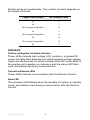
1.2 Remote Control
The Infrared Remote Control Model 5570 is used to communicate
and set the power and timing parameters. Unlike a typical consumer
remote control, the 5570 features a narrow infrared beam that
prevents communication errors with nearby AeroBars. For best
results, hold the remote control within 18-24 inches of an AeroBar’s
vertical centerline and aim directly at the receive LED of the
AeroBar. When the AeroBar receives transmission from the remote
control, it will flash all three LEDs for one second. Each successive
transmission is indicated with a one-second flash after the last
received transmission.
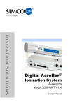
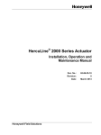
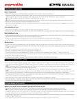
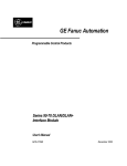
There are four buttons on the Remote Control 5570 (Up, Down,
Select, and Esc).
• The Up and Down buttons are used to scroll through menu
items.
• The Select button selects an item to be changed.
• The Esc button wakes the remote control from sleep mode, or
exits from the activity of a parameter being changed.
Figure 2. Remote Control Buttons
19-5225S-M-01 Rev 2
5
Passwords
The Remote Control features two levels of access: a User Menu
level, and a Technical Field Service (TFS) menu.
• The User Menu level allows you to view current AeroBar
settings, change the operation mode, change the positive and
negative output levels, and set the on times and off times.
• The TFS Menu is password-protected and all basic and
advanced parameters can be changed.
Both the User Menu and TFS Menu feature two lines of information.
The first line displays the item of the menu. The second line displays
the current adjustment level or operation mode for that item.
An on/off slide switch is featured on the right side of the remote
control. Upon powerup, the 5570 remote control shows the
following:
UsrMenu
Ver 2.6
Most menu items of the Remote Control require a password in order
to be changed. The positive and negative output levels of an
AeroBar can be changed without a password. The password is: Esc,
Down, Up, Select, Select, Select, Select.
Sleep Mode
The Remote Control Model 5570 automatically goes into sleep
mode if there is no button activity for 15 seconds. Press the Esc key
to awaken the remote control. While in sleep mode, the LCD
displays:
Use ESC
To Awake
If the battery is low during sleep mode, the bottom line is replaced
with LowBatt.
19-5225S-M-01 Rev 2
6
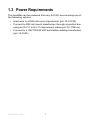
1.3 Power Requirements
The AeroBar can be powered from any 24 VAC source using one of
the following options:
• Hard wire to a DIN rail mount transformer (p/n 14-21730)
• Connect to DIN rail mount transformer through a junction box
using an RJ-11 to RJ-11 interconnect cable (p/n 33-1700-xx)
• Connect to a 100/115/230 VAC switchable desktop transformer
(p/n 14-1535).
19-5225S-M-01 Rev 2
7
19-5225S-M-01 Rev 2
8
2
Installation
2.1 Mounting
2.2 Wiring
2.3 FMS Connection
2.4 Daisy-chaining
19-5225S-M-01 Rev 2
9
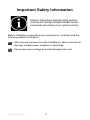
Important Safety Information
Failure to follow these important safety cautions
could result in damage to Digital AeroBar System
components and voiding of your system warranty.
Before installing or operating any components, carefully read the
following safety information:
After removing power from the AeroBar(s), allow a minute for
the high voltage power supplies to discharge.
Use proper input voltage to avoid damaging the unit.
19-5225S-M-01 Rev 2
10
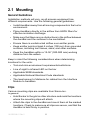
2.1 Mounting
General Guidelines
Installation methods will vary, as all process equipment has
different requirements. Use the following general guidelines:
• Install AeroBars away from all moving components in the tool or
environment.
• Place AeroBars directly in the airflow from HEPA filters for
effective ionization discharge.
• Make sure that there are no obstructions in the airflow between
the AeroBar and the surfaces to be neutralized.
• Ensure there is unobstructed airflow over emitter points.
• Keep emitter points at least 4 inches (100 mm) from grounded
surfaces, including tool frames, skins, and other modules.
• Keep the AeroBars within a 12-36” (300-900 mm) working
distance from the wafers.
Keep in mind the following considerations when determining
locations for the units:
• Tool and mini-environment requirements/restrictions
• Line of sight to infrared LED on the bar
• Applicable SEMI standards
• Applicable National Electrical Code standards
• The least amount of distance for cables from the Interface
Module to AeroBars
Clips
Various mounting clips are available from Simco-Ion.
In general:
• Hold the bar to the grid or other structure and mark the locations
where the mounting clips will attach.
• Attach the clips to the AeroBar and mount them at the marked
locations. Check to make sure all clips are secure, and that the
AeroBar is held firmly in position.
19-5225S-M-01 Rev 2
11
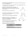
Flat metal clip (p/n 28-6255): Two required for 44” bars; three for
64", 76", and 84" bars.
A polycarobante rod and clip assembly is also available #93-1420
(4”), 93-1421 (8”), 93-1422 (12”)
Mid-clip for hang mount (p/n 28-6240): Use
alone or in conjunction with end clips for bars over
44" in length.
May be used with end clip 28-6235
Grid clip for perforated panels (p/n 28-6257):
Use for bars 44” or shorter.
Requires two pine tree fasteners #28-0505.
Eggcrate mid-clips (p/n 28-6230): Use
alone or in conjunction with end clips for
bars over 44" in length.
Requires eggcrate endclip #28-6225 with
two pine tree fasteners #28-0505.
Mounting Clip Recommendations
Bar Length
Number of Clips
22-44 inches (11.8–71.1 cm)
2
56-84 inches (162.6–213.4 cm)
3
19-5225S-M-01 Rev 2
12
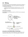
2.2 Wiring
The AeroBar may be hard wired directly to 24 VAC line voltage, or
to a 24 VAC transformer. Two 24 VAC transformer options are
available from Simco-Ion:
•
230/240 VAC DIN Rail Mount transformer (p/n 14-21730)
• 100/115/230 VAC switchable desktop transformer (p/n 141535)
Connection to Power
The AeroBar can be directly wired to a 24 VAC source using wire
terminations.
Figure 3. Interconnect Cable Information
Connection to the DIN Rail Mount Transformer
The interconnect cable can be connected to the DIN Rail mount
transformer (Simco-Ion p/n 14-21730) using either a bare wire
19-5225S-M-01 Rev 2
13
termination or an interconnect cable with an RJ-11 connector to a
Junction Box (p/n 33-1825) wired to the transformer. (An RJ-11
connector is used at the AeroBar.)
Direct Wire
To wire directly to the transformer, use the wiring diagram shown in
the figure below. Connect the 24 VAC and 24 VAC return wires and
cut the unused #3 wire. The Alarm line will be wired to an FMS
connection, if used.
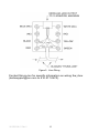
Figure 4. Wiring Interconnect Cable or J-box Directly to the Transformer
J-box Wiring
To use the RJ-11 connector, wire the junction box to the transformer
according to Figure 4 and physically attach it to the side of the
transformer or in close proximity to the transformer. See Figure 7 for
suggested mounting.
19-5225S-M-01 Rev 2
14
Figure 5. J-box Wiring
Contact Simco-Ion for specific information on wiring the j-box
(techsupport@ion.com or 510.217.0470).
19-5225S-M-01 Rev 2
15
Figure 6. J-box Mounting Suggestion
When using the FMS output connection with the DIN rail mount
transformer, the FMS signal must be wired to the your FMS system
either by direct wire or through a junction box alarm wire.
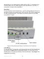
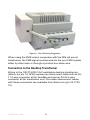
Connection to the Desktop Transformer
Wiring to the 100/115/230 VAC switchable desktop transformer
(Simco-Ion p/n 14-1535) requires an interconnect cable with an RJ11 4-wire connector at the AeroBar end and an RJ-22 4-wire
connector at the transformer end. Pre-made interconnect cables
with these connectors are available from Simco-Ion (p/n 33-172510).
19-5225S-M-01 Rev 2
16
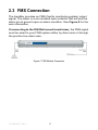
2.3 FMS Connection
The AeroBar provides an FMS (facility monitoring system) output
signal. The alarm is a non-isolated open collector that will pull the
alarm pin to ground upon an alarm condition. See Figure 4 for the
wire information.
If connecting to the DIN Rail mount transformer, the FMS signal
must be wired to your FMS system either by direct wire or through
the junction box alarm wire.
Figure 7. FMS Module Connection
19-5225S-M-01 Rev 2
17
2.4 Daisy-chaining
Where AeroBars are used together in the same tool or in close
proximity, it may be desirable to daisy-chain the AeroBars to the
same power source. Up to 10 AeroBars can be daisy-chained
together using standard interconnect cables in between the
AeroBars. Plug the connectors into the ends of each AeroBar and
connect the last cable to the power source.
If it is more convenient to wire the AeroBars in a drop-tee
configuration, junction boxes may installed at the tee sites and wired
together using 18-22 AWG cable. The RJ-11 connectors from the
AeroBar cables can then be plugged into the junction boxes.
Note:
In either the daisy-chain or the “Drop-T” configuration the alarm
outputs of all the ionizers will be logically “OR” together.
A bracket or hanging device may need to be constructed,
depending on your application. Wire management clips are
available to secure an AeroBar the cables to the topside of the
AeroBars where necessary to a custom bracket.
19-5225S-M-01 Rev 2
18
3
Operation
3.1 About AeroBar Adjustments
3.2 Using the Remote Control
3.3 Ionization Mode (OpMode)
3.4 Output Voltages
3.5 On- and Off-times (Pulsed DC Mode Only)
3.6 FMS Alarm Values
3.7 Balance Adjustment and System Calibration
19-5225S-M-01 Rev 2
19
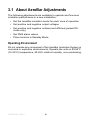
3.1 About AeroBar Adjustments
The following adjustments are available to operate and fine-tune
ionization performance in a new installation:
• Set the AeroBar ionization mode for each zone of operation
• Set positive and negative output voltages
• Set positive and negative ontimes and offtimes (pulsed DC
mode only)
• Set FMS alarm values
• Place Ionizers in Standby Mode
Operating Environment
Do not operate any component of the AeroBar Ionization System in
corrosive or explosive environments. Operate the units in 60-95°F
(16-35°C) temperature, 40-65% relative humidity, non-condensing.
19-5225S-M-01 Rev 2
20
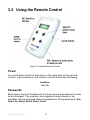
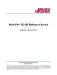
3.2 Using the Remote Control
Figure 8. Handheld Remote Control
Power
An on/off slide switch is featured on the right side of the remote
control. Upon powerup, the remote control shows the following:
UsrMenu
Ver 2.6
Passwords
Most menu items of the Remote Control require a password in order
to be changed. The positive and negative output levels of an
AeroBar can be changed without a password. The password is: Esc,
Down, Up, Select, Select, Select, Select.
19-5225S-M-01 Rev 2
21
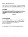
Battery Life and Replacement
The Remote Control uses two AA alkaline batteries. Life is
approximately 60 hours for full operation, and approximately 500
hours while in sleep mode. If the battery voltage drops to ~2V, low
battery will be indicated on the second line of the LCD display. Turn
the remote control off with the slide switch to conserve battery life.
Sleep Mode
The Remote Control Model 5570 automatically goes into sleep
mode if there is no button activity for 15 seconds. Press the Esc key
to awaken the remote control. While in sleep mode, the LCD
displays:
Use ESC
To Awake
If the battery is low during sleep mode, the bottom line is replaced
with LowBatt.
Garbled Responses
If you see “ReTry” or “&$%#” on the bottom line of the Remote
Control, the Remote Control may be too close to the AeroBar or is
not lined up correctly. Move farther away from the AeroBar and
target the infrared source at the center red LED.
Remote Control Menu
The following table lists the parameters in both menus of the
Remote Control. The TFSMenu is a password protected menu. Use
the UP or DOWN buttons to scroll through these parameters.
19-5225S-M-01 Rev 2
22
Password
TFSMenu
User Menu
Hold down any button while turning the remote control on
and then: Esc, Down, Up, Select, Select, Select, Select.
None
Status
Status
PosFdbk
PosOut
NegFdbk
NegOut
Address*
OpMode
PosOn
PosOff
PosOut
Pos Alarm
NegOn
NegOff
NegOut
Viewable
paramters
NegAlarm
Eprom
* This item is not applicable with the Model 5225S AeroBar but appears in the list of parameters
in the Remote Control.
19-5225S-M-01 Rev 2
23
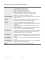
Descriptions of each parameter are below:
Status
Indicates the reported status of an AeroBar as follows:
Ok: if the AeroBar is operating normally.
Standby: if the AeroBar is in standby.
PosAlrm: if the positive emitter is in alarm.
NegAlrm: if the negative emitter is in alarm.
Pos&Neg: if both positive and negative emitters are in alarm.
Retry: if the AeroBar did not reply to a communication query.
#%&@$#: if the reply from the AeroBar is not valid.
PosFdbk/NegFdbk
The current feedback of the positive or negative emitter, given in percent.
Range is 0 to 100%.
Address
Not applicable with the Model 5225S AeroBar. The Remote Control is
used with several models of Simco-Ion Digital AeroBars.
OpMode
Indicates the operating mode of the AeroBar, as follows:
Standby: if the AeroBar is in standby. (AeroBar is powered but ionization
is turned off.)
StdySDC: if the AeroBar is continuously generating both positive and
negative ionization.
Pulse: if the AeroBar is alternately generating the positive or negative
ionization with an optional off period between polarities.
PosOn/PosOff
Indicates the internal timing for the “on” time of the positive emitter with a
range of 0.5 to 9.9 seconds, or internal timing for the “off” time of the
positive emitter with a range of 0.0 to 9.9 seconds.
NegOn/NegOff
Indicates the on time of the negative emitter, with a range of 0.5 to 9.9
seconds, or the off time of the negative emitter with a range of 0.0 to 9.9
seconds.
PosOut/NegOut
Indicates the output of the positive and negative emitters, with ranges of
0 to 100%.
PosAlrm/NegAlrm
Indicates the alarm setpoint with a range of 0 to 100%. For the AeroBar
Model 5225, this refers to the FMS alarm.
Eprom
Identifies the software release version of the AeroBar.
19-5225S-M-01 Rev 2
24
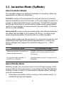
3.3 Ionization Mode (OpMode)
About Ionization Modes
The AeroBar allows two different methods of ionization. Both are
appropriate for different situations.
Pulsed DC mode is recommended for process tool environments
where the distance from the fan filter unit to the target exceeds 24
inches or where fast discharge is necessary. Pulsed DC provides
fast decay times and is a good choice unless large metal objects
(such as a pre-aligner or measurement tool) are within 12 inches
(30 cm) of the AeroBar.
Steady-state DC mode is recommended when the distance between
the wafer and AeroBar is 8-2 inches (20-30 cm), or when large
metal objects are within 12 inches (30 cm) of the AeroBar.
Steady-state mode may be necessary for most semiconductor tool
applications with tight performance specifications, or when low
swing voltages are required for sensitive devices (i.e., <100V
swings).
Use Pulsed DC Mode
Use Steady-state DC Mode
Distances greater than 24 inches (61 cm)
between AeroBar and wafer
Distances 8-2 inches (20-30 cm) between AeroBar
and wafer, and for sensitive devices (less than
100V swings)
No large metal objects are within 12
inches (30 cm) of AeroBar
Large metal objects are within 12 inches (30 cm) of
the AeroBar
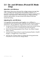
About Standby Mode
Standby mode is a convenient way to turn off high voltage to the
ionizer without removing wires or accessing the Interface Module.
Standby mode is useful for maintenance periods where settings
must be remembered.
1. Hold down any button while turning on the remote control. A
password prompt will appear.
19-5225S-M-01 Rev 2
25
2. Enter in the following password: Esc, Down, Up, Select,
Select, Select, Select.
3. Use the Up or Down button to reach the OpMode item. Press
Select.
4. Point the remote control directly at the LEDs on the AeroBar
and use the Up or Down button to select the operation mode
(Standby, Pulsed, or StdySDC). Press Esc to exit.
19-5225S-M-01 Rev 2
26
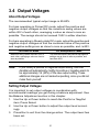
3.4 Output Voltages
About Output Voltages
The recommended typical output range is 50-80%.
For bars operating in Pulsed DC mode, adjust the positive and
negative output voltages so that the maximum swing values are
within 20V of each other, averaging a value as close to zero as
possible. The swings should not exceed 150V in either direction.
For bars operating in Steady-state DC mode, adjust the positive and
negative output voltages so that the combined value of the positive
and negative settings are as close to zero as possible, and <±20V.
For Pulsed DC Mode
Maximum swing values are within 20V of
each other, averaging a value as close to
zero as possible.
Note:
For Steady-state DC Mode
The combined value of the positive and negative
settings are as close to zero as possible, and
less than ±20V.
If you modify a positive or negative output setting, then that
AeroBar will automatically modify its positive or negative alarm to
be approximately 1/4 (25%) of the new output setting. These
additional changes are not marked as pending, since you did not
make them yourself.
Setting Output Voltages
It is important to set output voltages in coordination with
environmental readings you get during a balance adjustment. See
the Balance Adjustment section in this chapter.
1. Use the Up or Down button to reach the PosOut or NegOut
item. Press Select.
2. Use the Up or Down button to adjust the output level accordingly.
3. Press Esc to exit from the change action. The output level has
been set.
19-5225S-M-01 Rev 2
27
3.5 On- and Off-times (Pulsed DC Mode
Only)
About On- and Off-times
If the decay time is too slow and the voltage swings are less than
100V, increase both the positive and negative ontimes in 0.1
second increments, checking the positive and negative decay times
between each adjustment. When changes no longer positively
improve performance, set the ontime and offtime at the last
beneficial setting.
Adjusting On- and Off-times.
It is important to set positive and negative on or offtimes in
coordination with environmental readings you get during a balance
adjustment. See the Balance Adjustment section in this chapter.
1. Access the TFS Menu by holding down any button while turning
on the remote control. A password prompt will appear.
2. Enter the following password: Esc, Down, Up, Select, Select,
Select, Select.
3. Use the Up or Down button to reach the desired PosOn, PosOff,
NegOn, or NegOff item. Press Select.
4. Use the Up or Down button to change the timing parameter.
Press Esc to exit from the change action.
19-5225S-M-01 Rev 2
28
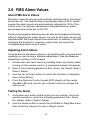
3.6 FMS Alarm Values
About FMS Alarm Values
Normally, alarm levels are automatically adjusted when the output
levels are set. The default alarm percentage value is 25%, which
means the alarm levels are automatically adjusted to 25% of the
output level. For proper maintenance and performance, alarm
percentage should be set to 50-75%.
Positive and negative alarm levels can also be changed individually,
without changing the output levels, as long as the alarm levels are
adjusted after the output levels have been set. In addition, note that
changing the positive or negative output level will cause the
corresponding alarm level to reset.
Adjusting Alarm Values
It is important to set alarm values in coordination with environmental
readings you get during a balance adjustment. See the Balance
Adjustment section in this chapter.
1. Access the user-level menu by holding down any button while
turning on the remote control. A password prompt will appear.
2. Enter in the following password: Esc, Down, Up, Select, Select,
Select, Select.
3. Use the Up or Down button to reach the PosAlrm or NegAlrm
item, Press Select.
4. Point the Remote Control model 5570 directly at the center
AeroBar LED and use the Up or Down button to change the
alarm level
Testing the Alarm
1. Hold down any button while turning on the remote. Once the
remote comes on, enter the following password: Esc, Down,
Up, Select, Select, Select, Select.
2. Use the Down button to reach the PosFdbk or NegFdbk menu
item. Note the value(s) for use in Step 4 below.
19-5225S-M-01 Rev 2
29
3. Continue pressing the down button until you reach the PosAlrm
or NegAlrm menu item. Press Select.
4. Use the Up button to change the alarm level so that it is above
the corresponding Pos or Neg FeedBack level. (Change the
alarm levels one at a time.)
19-5225S-M-01 Rev 2
30
3.7 Balance Adjustment and System
Calibration
Simco-Ion balance adjustment and calibration procedure is a
regular part of installation and maintenance of the AeroBar and its
components. Adjustment for the AeroBar may be performed at
initial installation, during periodic checks of the entire system, or
anytime additional components are added to the system.
This section consists of the following information:
•
•
•
•
About Adjustment and Calibration
Tool parameters that Affect Ionization
Performing the Adjustment
Understanding Ionization Modes, Voltage Swing and Output,
and Decay Timing
• Troubleshooting
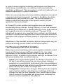
Goals of Balance Adjustment and System Calibration
•
•
•
•
Balanced, high ion density arriving to the surfaces and wafers
Similar positive and negative decay times
Maximum decay in the amount of available time
Moderate voltage swings (Pulsed DC) or voltage offset (Steadystate DC) to eliminate the possibility of inducing voltage on the
surfaces
Recommended Equipment
• Charge Plate Monitor Model 280A
• Tripod (optional)
• Anemometer
About Adjustment and Calibration
Environment variables and the physical properties of ions can lead
to degraded ionization performance over time. This leads to a
greater risk of static or the presence of voltage on your sensitive
product surface.
19-5225S-M-01 Rev 2
31
In order to ensure optimal ionization performance and therefore
static charge neutralization, ion delivery must be periodically
regulated, or balanced. This procedure is commonly referred to as
balance adjustment or system calibration.
Simco-Ion recommends performing a balance adjustment as part of
a regular maintenance program. In general, AeroBars should be
balanced every six months to a year. The actual frequency of
balance adjustment depends on the specific activity of your
application and environment.
In Pulsed DC mode, positive and negative ions are released
sequentially during ontimes. During offtimes, no ions are released
and existing ions disperse. In Steady-state DC mode, both positive
and negative ions are constantly produced. The goal of the
adjustment procedure is to regulate the ion delivery, so that equal
numbers of positive and negative ions arrive at the work surface to
neutralize static charges of either polarity in a specified amount of
time.
Adjustment of the AeroBar Ionziation System components may be
performed during periodic checks of the entire system.
Tool Parameters that Affect Ionization
Balancing involves adjusting positive and negative ionization output
levels and timing sequence of these outputs. You can make
adjustments to the AeroBar Model 5225S settings using the
Remote Control. In addition to the ionizer settings, be aware of the
following variables that can affect balance:
• Airflow: The recommended airflow for effective ionization is 7090 fpm. Low airflow moves the ions more slowly, allowing
potential ion recombination and reducing the ions available to
neutralize surfaces. High airflow moves the ions in a more direct
path, reducing the surface coverage area.
• Configuration: Configuration changes differing from the original
spec (such as adding a pre-aligner or metrology tool) may
change the way the ions disperse. Also, metal objects closer
than 6 inches to the AeroBar will ground ions, reducing the
amount of ions available to the surfaces.
19-5225S-M-01 Rev 2
32
• Maintenance: Contaminants in the environment are attracted to
AeroBar emitter points. Dirty emitter points have an adverse
effect on ion output and voltage balance. As a general rule,
emitter points should be cleaned every 3 months, and AeroBars
should be rebalanced every 6 months to a year.
• Environment: Changes in cleanroom humidity and background
airflow may affect performance.
• Location: AeroBar settings are based on the performance at a
designed-in location. Repositioning or changing the mounting
distance from the FFU will affect performance results.
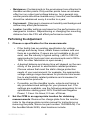
Performing the Adjustment
1. Choose a specification for the measurements:
• If the facility has an existing specification for voltage
swings and decay times, obtain these numbers and use
them as a guideline. If specs are not available or do not
exist, use the industry’s typical setting. (±50 to 100V for
semiconductor tools and mini-environments and ±100 to
150V for other fabrication in open areas.)
• A desired balance and decay time will depend on the sensitivity of the product to electrostatic-related problems.
Choose values that meet the static charge protection
needs of your environment; for example, the appropriate
voltage swings range decreases for products more sensitive to electrostatic-related problems and increases for
less sensitive products.
• If possible, set the AeroBar mode, outputs and timing to
any pre-determined settings for your process tool. If no
settings are available, use the following parameters for an
optimization starting point: 50% Positive and Negative
Power; 1.0 sec. 0n-times; 0.2 sec. off-times.
2. Set the CPM in an appropriate location for obtaining
measurements: Remove the charge plate from the monitor
(refer to the charge plate monitor manual for instructions on
removing the plate, Simco-Ion part number 19-0280A-M). For
the AeroBar Model 5225, ideal locations include:
19-5225S-M-01 Rev 2
33
•
•
•
•
•
Centralized in the mini environment chamber
Next to a FOUP port
On a pre-aligner
On a metrology module
On a buffer stations
After placing the CPM in its location, step away. Standing too
close to the CPM may interfere with airflow and ion movement.
Make sure all access doors are closed.
3. Record the Airflow: Use an anemometer to measure the
airflow at the height of the CPM plate. Record the air flow along
with the CPM measurements obtained at each sample location.
Too high or low of an airflow rate will affect the true balance
behavior of the ions. The recommended airflow for optimal
ionization is 70-90 fpm.
4. Take the measurements on the CPM: The measurements
taken on the CPM will record the following specifics:
• Positive and negative peak voltages
• Balance (an average of the positive and negative voltage
peaks)
• Positive and negative decay time
a) Allow the CPM to warm up for at least 15 minutes.
b) From the Main screen on the Model 280A CPM:
Press Auto. The Auto test performs both Decay tests,
followed by a balance test.
Make sure the symbol "D>" is next to the test you want
(usually the "Factory" test, which runs an auto test with
standardized test parameters).
Press Start
c) Note the numbers for +Vp (positive voltage peak), -Vp
(negative voltage peak), and Vave (average or balance).
5. Examine the Data and Adjust the AeroBars: If the measurements have been taken for an operation area do not meet your
specifications, use the Remote Control to adjust the AeroBar
settings.
19-5225S-M-01 Rev 2
34
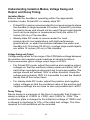
Understanding Ionization Modes, Voltage Swing and
Output, and Decay Timing
Ionization Modes
Ensure that the AeroBar is operating within the appropriate
ionization mode: Pulsed DC or steady-state DC:
• Pulsed DC mode is recommended for tool environments where
the AeroBar to target exceeds 24 inches. Pulsed DC provides
fast decay times and should not be used if large metal objects
(such as a pre-aligner or measurement tool) are within 12
inches (30 cm) of the AeroBar.
• Steady-state DC mode is recommended for most
semiconductor tool applications with tight performance
specifications, or when the distance between the wafer and
AeroBar is 8-12 inches (20-30 cm), or when large metal objects
are within 12 inches (30 cm) of the AeroBar.
Voltage Swing and Output
Voltage swing refers to the range of the CPM plate voltage between
the positive and negative peak readings at sample locations.
The recommended typical voltage output range is 50-80%.
• For Pulsed DC mode, adjust the positive and negative output
voltages so that the maximum swing values are within 20V of
each other--averaging a value as close to zero as possible. The
swings should not exceed 150V in either direction. Keep the
voltage swings below 100V if it is possible to meet the desired
decay time at this output level.
• For steady-state DC mode, adjust the positive and negative
output voltages so that the combined value of the positive and
negative settings are as close to zero as possible and <±20V.
Decay Timing
Decay timing is a measure of the time (in seconds) that it takes to
decay a charge of +1000V to +100V, and -1000V to -100V. The
conductive plate is charged to the initial test voltage of 1000V and
is allowed to discharge to 10% of the initial test voltage. The time
required for both polarities will be recorded.
19-5225S-M-01 Rev 2
35
In Pulsed DC mode, if decay times are too slow and voltage swings
are greater than 100V, increase the positive and negative offtimes
in 0.1 second increments. In steady-state mode, increase the
positive and negative voltage outputs if the decay times are too
long.
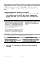
Troubleshooting the Balancing Procedure
1. If decay times are too long: Check that airflow is 70-90 fpm.
If airflow is too low and cannot be changed, see the table,
Airflows Are Lower Than Tool Specification and Cannot Be
Changed:
For Pulsed DC Mode
For Steady-state DC Mode
If voltage swings are <100V, adjust + and - ontimes
upward in 0.1 second increments until decay time
stops improving or voltage swings become too high.
Maintain last beneficial setting. Do not set below 0.7
seconds or alarms will be defeated. The normal
range is 0.7 to 2 seconds.
Increase the positive and negative
voltage outputs, maintaining a balance
of ±20V.
If voltage swings are >100V, adjust + and - offtimes
upward in 1 second increments until decay time
stops improving or voltage swings become too high.
Maintain last beneficial setting.
2. If voltage swings are too high (pulsed DC only):
If Voltage Outputs are >80%
If Voltage Outputs are <50%
Decrease voltage outputs in 0.1%
increments, maintaining balance, until swings
are <100V or in desired range.
Decrease positive or negative on or offtimes in
0.1% increments, maintaining balance, until
swings are <100V or in desired range
3. If airflows are lower than tool specification and cannot be
changed:
19-5225S-M-01 Rev 2
36
For Pulsed DC Mode
1. Increase voltage outputs in 1%
increments, maintaining balance until
swings reach 100-150V. Do not exceed 90%
output. If decay times are still too long,
proceed to the next step.
For Steady-state Mode
1. Increase voltage outputs in 0.1%
increments, maintaining balance until output
reaches 90%.
2. If decay time is still too long, switch to Pulsed
DC mode and balance.
2. Increase + and - ontimes in 0.1 second
increments, maintaining balance, until decay
time improves or voltage swings become too
high. Maintain last beneficial setting.
3. Increase + and - offtimes in 0.1 second
increments, maintaining balance, until
performance stops improving. Maintain last
beneficial setting.
19-5225S-M-01 Rev 2
37
19-5225S-M-01 Rev 2
38
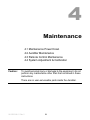
4
Maintenance
4.1 Maintenance Power Down
4.2 AeroBar Maintenance
4.3 Remote Control Maintenance
4.4 System Adjustment & Calibration
Caution:
To avoid personal injury or damage to the equipment, do not
perform any maintenance other than that contained in these
instructions.
There are no user-serviceable parts inside the AeroBar.
19-5225S-M-01 Rev 2
39
4.1 Maintenance Power Down
Before performing any maintenance, the AeroBar must be powered
down.
Warning:
Never power-down by removing the power cable from the
AeroBar, as this can result in damage to the ionizer.
To power-down the AeroBar, put the AeroBar in standby
mode, turn off the power source, or disconnect the cable from
the power source end.
Standby mode is a convenient way to turn off high voltage to the
ionizer without removing wires. Standby mode is useful for
maintenance periods where settings must be remembered.
1. Hold down any button while turning on the remote control. A
password prompt will appear.
2. Enter in the following password: Esc, Down, Up, Select,
Select, Select, Select.
3. Use the Up or Down button to reach the OpMode item. Press
Select.
4. Point the remote control directly at the LEDs on the AeroBar
and use the Up or Down button to select the operation mode
(Standby, Pulsed, or StdySDC). Press Esc to exit.
19-5225S-M-01 Rev 2
40
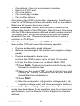
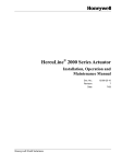
4.2 AeroBar Maintenance
Primary maintenance for the AeroBar consists of periodic emitter
point cleaning and replacement, system calibration, and exterior
cleaning of the chassis. As maintenance schedules will vary
depending on conditions, develop a schedule which meets the
requirements for your application. In general, equipment should be
checked on a monthly basis to ensure it is operating as originally
set.
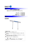
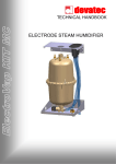
Emitter point cleaning is recommended every three to six months,
and replacement every 24 to 36 months or when damage or erosion
is evident. Calibration may be performed quarterly, semiannually, or
annually depending on your application. Always clean the emitter
points prior to calibration. Cleaning emitter points after calibration
will alter the calibrated settings.
Where AeroBars are used in environments containing airborne
molecular contaminates (AMC), emitter points should be cleaned
every one to three months or wherever significant amounts of debris
have accumulated on emitter tips.
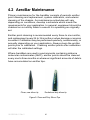
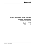
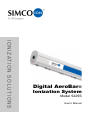
Clean, new silicon tip
Eroded and dirty silicon tip
Figure 9. Clean and Dirty Silicon Tips
19-5225S-M-01 Rev 2
41
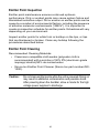
Emitter Point Inspection
Emitter point maintenance ensures continued optimum
performance. Dirty or eroded points may cause system failure and
diminished ionization output. Dirt or erosion on emitter points can be
cause by a number of environmental factors, including the presence
of airborne molecular contaminants ("AMCs"). It is important to
create an inspection schedule for emitter points. Schedules will vary
depending on your environment.
Inspect emitter points for white fuzz or buildup on the tips, or tips
that are blackened or broken. Clean any buildup following the
procedures described below.
Emitter Point Cleaning
Recommended Cleaning Materials:
• Cleanroom-compatible cloth swabs (polyester cloth is
recommended) with a solution of 50% IPA (electronic-grade
isopropyl alcohol)/50% de-ionized water.
• Simco-Ion Emitter Point Cleaner (Simco-Ion part number #221000).
Caution:
Do not clean emitter points while the unit is powered. Doing so
may result in additional contamination and possible shock.
After powering down the AeroBar, allow a minute for the high
voltage power supplies to discharge.
19-5225S-M-01 Rev 2
42
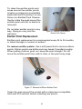
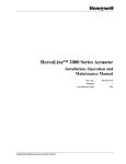
To clean the emitter points and
areas around the emitter points,
moisten a cleanroom-compatible
swab with the IPA solution, or use
Simco-Ion Emitter Point Cleaner.
Gently rotate the swab around the
emitter point until dirt or debris is
removed.
Do not alter emitter points in any
way. Doing so may void the
warranty.
Figure 10. Cleaning Points with the
Emitter Point Cleaner
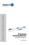
Emitter Point Replacement
Emitter point replacement is recommended every 24 to 36 months,
or when damage or erosion is evident.
To remove emitter points: Use a soft-jawed tool to remove silicon
points. Silicon points are brittle and may break if handled roughly.
When pulling a silicon point out, keep the point straight. Do not
move the emitter point from side to side, or the point may snap.
Figure 11. Removal of Silicon Emitter Point
Clean the area around the socket with a cleanroom-compatible
cloth and IPA solution before inserting new points.
19-5225S-M-01 Rev 2
43
To insert new emitter points: Gently insert and press the new
emitter point into the socket until it is fully seated. Do not push on
the tip of the emitter point.
Chassis Cleaning
Use a cleanroom-compatible cloth moistened with 50% IPA and
50% de-ionized water to wipe down the chassis. Do not use any
cleaners or solvents.
19-5225S-M-01 Rev 2
44
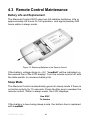
4.3 Remote Control Maintenance
Battery Life and Replacement
The Remote Control 5570 uses two AA alkaline batteries. Life is
approximately 60 hours for full operation, and approximately 500
hours while in sleep mode.
Figure 12. Replacing Batteries in the Remote Control
If the battery voltage drops to ~2V, “LowBatt” will be indicated on
the second line of the LCD display. Turn the remote control off with
the slide switch to conserve battery life.
Sleep Mode
The Remote Control automatically goes into sleep mode if there is
no button activity for 15 seconds. Press the Esc key to awaken the
remote control. While in sleep mode, the LCD displays:
Use ESC
To Awake
If the battery is low during sleep mode, the bottom line is replaced
with LowBatt.
19-5225S-M-01 Rev 2
45
4.4 System Adjustment & Calibration
Adjustment and calibration should be performed as a regular part of
installation and maintenance activity.
Refer to Chapter 3 Operation for instructions on adjusting and
calibrating the system.
19-5225S-M-01 Rev 2
46
19-5225S-M-01 Rev 2
47
5
Specifications
5.1 AeroBar Model 5225S
5.2 Parts & Accessories
5.3 Dimensional Drawings
19-5225S-M-01 Rev 2
48
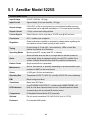
5.1 AeroBar Model 5225S
AeroBar Model 5225S
Input Voltage
24 VAC, 50/60 Hz, 1W (typ)
Input Current
Approximately 40 mA per AeroBar, 1W (typ)
Output Voltage
0-20 kVDC, ±10% for each polarity on an individual AeroBar; pos/neg
output levels can be adjusted separately in 0.1% output power resolution
Output Current
<15 µA, current and voltage limited
Control Signals
Open Collector, Active Low Alarm, 40 VDC max @ 200 mA max
Connectors
RJ-11 modular jack receptacle
Regulation
Output and balance stability is achieved by independently regulating the
ion emission current of each polarity at each ionizer
Timing
Precise timing (0-10 sec @ 0.1 sec resolution); LEDs on each Bar
indicate the polarity of ion emission
Operating Modes
Bipolar pulsed DC, steady-state DC, or standby
Alarm
Alarm activates when the bar is no longer able to maintain preset ion
output levels. Alarm is displayed visually via red LED in middle of the
chassis. Settable threshold alarm limits for predictive maintenance.
Emitter Points
Single-crystal silicon; replaceable
Maintenance
Annual, semi-annual, or quarterly, depending on process sensitivity and
presence of AMCs in the environment
Ozone
<0.005 ppm (24-hour accumulation)
Operating Env.
Temperature 60-95°F (16-35°C); humidity 40-65% RH, non-condensing
EMI
Below background level
Cleanliness
Better than ISO Class 1
LED Indicators
2 red POS/NEG ION OUTPUT; 1 middle red ALARM/STANDBY; all 3
blink at once when communication occurs; 2 transmit/receive indicate
communication with an optional IR remote control
Components
IR Handheld Remote Model 5570 (required)
Optional
Din rail mount transofrmer 230 VAC/24 VAC (p/n 14-21730)
Enclosure
Fire-retardant ABS plastic
19-5225S-M-01 Rev 2
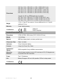
49
Dimensions
22.4” bar: 2.1H x 1.2W x 22L in. (5.3H x 3.05W x 56.9L mm)
28.4” bar: 2.1H x 1.2W x 28L in. (5.3H x 3.05W x 72.1L mm)
44.4” bar: 2.1H x 1.2W x 44L in. (53H x 30.5W x 112.8L mm)
64.4” bar: 2.1H x 1.2W x 64L in. (53H x 30.5W x 163.6L mm)
84.4” bar: 2.1H x 1.2W x 84L in. (53H x 30.5W x 214.4L mm)
3 lengths for 300 mm EFEM applications available:
35.7” bar: 2.1H x 1.2W x 35.7L in. (53H x 30.5W x 90.7L mm)
55.6” bar: 2.1H x 1.2W x 55.6L in. (53H x 30.5W x 141.2L mm)
75.5” bar: 2.1H x 1.2W x 75.5L in. (53H x 30.5W x 191.8L mm)
Weight
1.5 lb, (1.0 kg), 22” bar; approx. 6 oz oer additional foot (0.17 kg per
additional 30 cm)
Warranty
2 year limited warranty
SEMI F47
RoHS Compliant
Certifications
Handheld Remote Model 5570
Dimensions
4.75H x 2.75W x .88L inches (12.07 x 6.99 x 2.22 cm)
Weight
1 lb (0.46 kg)
Material
ABS high-impact plastic, minimum particle traps
Cleanroom Class
Class 1 or better
Indicators
2-line, 8-character display
Controls
4 keys: Up, Down, Esc, Select
Input/output
Signals
IRDA compatible 2-way InfraRed communication.
Operating
Distance
Infrared range operates at a min of 2 ft. and max of 10 ft.; 22-degree cone
of operation from the transmitter
Power
Two 1.5V batteries
Life
Battery life approx. 60 hrs in full operation, 500 hrs in sleep mode
Certifications
19-5225S-M-01 Rev 2
50
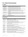
5.2 Parts & Accessories
AeroBars
91-5225SU-22R
22” AeroBar with Ultraclean (Silicon) Emitter Points (5)
91-5225SU-28R
28” AeroBar with Ultraclean (Silicon) Emitter Points (7)
91-5225SU-44R
44” AeroBar with Ultraclean (Silicon) Emitter Points (9)
91-5225SU-64R
64” AeroBar with Ultraclean (Silicon) Emitter Points (13)
91-5225SU-84R
84” AeroBar with Ultraclean (Silicon) Emitter Points (17)
91-5225SU-36R
36” AeroBar with Ultraclean (Silicon) Emitter Points (8), 2-load port
configuration
91-5225SU-56R
56” AeroBar with Ultraclean (Silicon) Emitter Points (12), 3-load port
configuration
91-5225SU-76R
76” AeroBar with Ultraclean (Silicon) Emitter Points (16), 4-load port
configuration
91-5570
Infrared Handheld Remote
Accessories
33-1700-X
Interconnect cable, RJ-11 connectors, 26 AWG, 4-conductor, where X is the
length: 0.5, 2, 6, 10, 15, 20, 30, 40 feet
14-21730
DIN rail mount transformer, 230 VAC to 24 VAC
14-1535
100/115/230 VAC switchable desktop transformer
14-1725-10
Interconnect cable for use with 14-15353 transformer, RJ-11 to RJ-22
connectors, 10 ft long
28-6225
End-clip for Egg Crate (2 clips required per bar)
28-6230
Mid-clip for Egg Crate (Each)
28-6235
End-clip for hang mounting (2 clips required per bar)
28-6240
Mid-clip for hang mounting (required for 64” and 84” bars only)
28-6255
Flat clip for Horizontal Mounting (2 required for 44”; 3 required for 64” & 84”)
28-0505
Pine Tree Clips (use two per end or grid clip)
28-6257
Grid Mounting Clips, requires two Pine Tree clips (28-0505) per Grid clip
28-6245
Wire Clips to secure cables to AeroBar
93-1420
Polycarbonate Rod and Flat Clip Assembly for lowering AeroBar clear 4”
19-5225S-M-01 Rev 2
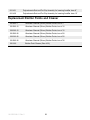
51
93-1421
Polycarbonate Rod and Flat Clip Assembly for lowering AeroBar clear 8”
93-1422
Polycarbonate Rod and Flat Clip Assembly for lowering AeroBar clear 12”
Replacement Emitter Points and Cleaner
22-0365-1
Ultraclean Sleeved (Silicon) Emitter Points, box of 1
22-0365-10
Ultraclean Sleeved (Silicon) Emitter Points, box of 10
22-0365-15
Ultraclean Sleeved (Silicon) Emitter Points, box of 15
22-0365-20
Ultraclean Sleeved (Silicon) Emitter Points, box of 20
22-0365-25
Ultraclean Sleeved (Silicon) Emitter Points, box of 25
22-0365-30
Ultraclean Sleeved (Silicon) Emitter Points, box of 30
22-1000
Emitter Point Cleaner (Box of 50)
19-5225S-M-01 Rev 2
52
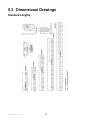
5.3 Dimensional Drawings
Standard Lengths
19-5225S-M-01 Rev 2
53
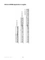
300 mm EFEM Application Lengths
19-5225S-M-01 Rev 2
54
19-5225S-M-01 Rev 2
55
6
Warranty & Service
Simco-Ion provides a limited warranty for the AeroBar Model 5225S
and Remote Control Model 5570. New products manufactured or
sold by Simco-Ion are guaranteed to be free from defects in material
or workmanship for a period of two (2) years from date of initial
shipment. Simco-Ion liability under its new product warranty is
limited to servicing (evaluating, repairing, or replacing) any unit
returned to Simco-Ion that has not been subjected to misuse,
neglect, lack of routine maintenance, repair, alteration, or accident.
In no event is Simco-Ion be liable for collateral or consequential
damages. Consumable items such as, but not exclusive to, emitter
points, emitter wires, batteries, filters, fuses or light bulbs are only
covered under this warranty if found defective as received with the
new product.
To obtain service under this warranty, please contact Simco-Ion
Technical Support at techsupport@simco-ion.com or (510) 2170470.
19-5225S-M-01 Rev 2
56
19-5225S-M-01 Rev 2
57
Notes
19-5225S-M-01 Rev 2
58
Notes
Technology Group
1750 North Loop Rd., Ste. 100
Alameda, CA USA 94502
Tel: 510-217-0600
Fax: 510-217-0484
Toll free: 800-367-2452
Sales services: 510-217-0460
Tech support: 510-217-0470
ioninfo@simco-ion.com
salesservices@simco-ion.com
techsupport@simco-ion.com
service@simco-ion.com
www.simco-ion.com
19-5225S-M-01 Rev 2