1
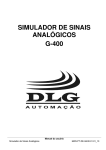
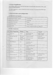
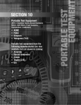
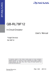
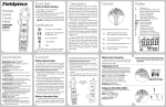
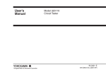
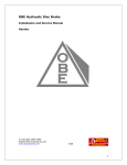
Safety Precautions
User’s
Manual
To ensure safe use of the product, strictly adhere to the precautions indicated by the following
symbols throughout this manual.
Model 73301/ 02/ 03
Digital Multimeters
Indicates a hazard that may result in the loss of life or serious injury of
WARNING the user unless the described instruction is abided by.
Indicates a hazard that may result in an injury to the user and/or physical
CAUTION damage to the product or other equipment unless the described instruction is abided by.
The instrument and this manual also use the following safety symbols:
Caution
This symbol indicates that the operator must refer to an explanation in the
instruction manual in order to avoid the risk of injury or death of personnel and/or
damage to the instrument.
Double Insulation
This symbol indicates double insulation.
AC Voltage/Current
This symbol indicates AC voltage/current.
DC Voltage/Current
This symbol indicates DC voltage/current.
Fuse
This symbol indicates a fuse.
Ground
This symbol indicates ground (earth).
2) SELECT key
This button is enabled only if the multimeter is in one of the following measurement modes.
•
V:
In this mode, the key selects the frequency measurement in hertz (73302 & 73303).
In this mode, the key selects the AC voltage measurement in an average value.
(73303)
• mV:
In this mode, the key selects AC voltage measurement in milli-volts.
• Ω:
In this mode, the key selects among the continuity check, diode test, and temperature measurement.
•
:
In this mode, the button adjusts the stray capacitance of the testing leads and the
multimeter itself, to zero (73302 & 73303).
• µA/mA/A: In this mode, the button selects AC current measurement.
3) RANGE key
Allows the operator to select the measuring range manually (the display shows the R • H symbol). The range increases as the button is pressed.
To return to the normal auto-ranging mode, hold down this button for at least one second until
the display shows " AUTO ."
4) D-H/A-H key
Selects between the DATA HOLD and AUTO HOLD functions (the display shows the D • H
symbol when in the DATA HOLD mode, and the A • H symbol when in the AUTO HOLD mode).
5) REL/% key
Selects between REL and % calculations (the display shows the REL symbol when in the
REL mode, and the REL and % symbols when in the % mode).
6th Edition: Jan. 2007(KP)
Connect the calibrator to the multimeter with the calibrator’s testing leads.
Before carrying out calibration, read the instruction manual of the calibrator.
Calibration temperature and humidity: 23±3°C, 55%RH or below
Leave the multimeter for 30 minutes to enable it to reach room temperature before
carrying out calibration.
• Temporarily remove the testing leads from the multimeter before switching between
DC and AC, or voltage and current during calibration.
To calibrate the multimeter:
Note: Start calibration of the mV range (calibration of other ranges will become possible after
mV calibration has been completed).
a) Turn the function switch from the OFF position to the mV position while pressing the SELECT and RANGE keys at the same time. (The display shows the CAL symbol then the
PASS symbol.)
b) Press the SELECT key. (The display shows the “- “ symbol.)
c) Press the D-H/A-H key twice. (The display shows the “- - - “ symbol.)
d) Press the RANGE key. (The display shows the mV symbol.)
e) Connect the multimeter to the calibrator with the testing leads.
f) Set the calibrator to 380 mVDC as an input to the multimeter.
g) Press the D-H/A-H key.
(After the value stabilizes, press the D-H/A-H key to confirm the calibration value.)
h) Carry out calibration of other ranges by repeating steps f) and g) in accordance to Table 1.
i) To quit calibration, turn the function switch back to the OFF position.
Table 1. Input Signal for Calibration
Range
400 mVDC
4 VDC
40 VDC
400 VDC
1000 VDC
VAC (RMS)
VAC (AVG)
Input
380 mV
3.8 V
38 V
380 V
1000 V
3.8 V at 60 Hz
3.8 V at 60 Hz
Range
400 µADC
4000 µADC
40 mADC
400 mADC
4 ADC
10 ADC
AAC
Input
380 µA
3800 µA
38 mA
380 mA
3.8 A
10 A
38 mA at 60 Hz
Range
10 nF
100 nF
1 µF
10 µF
100 µF
1000 µF
<5> REL/% key
<4> D-H/A-H key
<1> Function switch
Input
9 nF
90 nF
0.9 µF
9 µF
90 µF
1000 µF
a) Turn the function switch from the OFF position to the Ω position.
b) Plug the black testing lead into the COM input terminal and the red testing lead into
the
•V•Ω•
input terminal.
c) Connect the testing leads to the circuit under test and then read the meter when it stabilizes.
• Continuity Check (
)
CAUTION
• Diode Test (
)
CAUTION
To avoid damage to instrument
Turn off the power to the circuit under test before starting measurement in order to prevent any excess voltage from being applied to the multimeter.
Input terminal
6) Display Description
Symbol and Unit
Maximum Input Voltage
III
600 V AC/DC
II
1000 V AC/DC
REL
D•H
A•H
CAT.I
CAT.II
•
•
•
•
CAUTION
To avoid damage to instrument
Turn off the power to the circuit under test before starting measurement in order to prevent any excessive voltage from being applied to the multimeter.
WARNING
Measurement Category (CAT)
CAUTION
• Resistance Measurement (Ω)
a) Turn the function switch from the OFF position to the Ω position.
b) Press the SELECT key to display the
symbol.
•
c) Plug the black testing lead into the COM input terminal and the red testing lead into the
V•Ω•
input terminal.
d) Connect the testing leads to the circuit under test. If the circuit is continuous (no more than
approximately 20 Ω, the buzzer sounds.
<3> RANGE key
■ Measurement Category (CAT.)
The restrictions on the maximum voltage level for which the 73301, 73302 and 73303
multimeters can be used, depend on the Measurement categories specified by the safety
standards.
User Calibration Function
It is recommended that the instrument be calibrated periodically.
Use the keys on the faceplate of 733 series of multimeters to carry out calibration.
Use the calibrator with ten times the accuracy of 733 series.
Do not mistake the following for a malfunction!
If the 400 mV range is selected and the testing leads are left open-circuited, the multimeter may give a certain reading. This does not affect your measurement.
<2> SELECT key
■ To avoid electric shock
• Do not use deteriorated or damaged testing leads. Check testing leads before use.
• Do not use the instrument if there is any damage to the casing or when the casing is
removed.
• Disconnect testing leads from the circuit under test before opening the casing to replace the batteries or for any other reason.
• Avoid using the instrument if it has been exposed to rain or moisture or if your hands are wet.
■ To avoid electric shock or fire
Do not use the instrument in an atmosphere containing any flammable or explosive gases.
IM 73301E
NOTE
To avoid damage to instrument
Turn off the power to the circuit under test before starting measurement in order to prevent any excessive voltage from being applied to the multimeter.
<6> Display
WARNING
Store this manual in a safe place for
future reference.
c) Connect the testing leads to the circuit under test and then read the meter when it stabilizes.
For measurements performed on circuits not directly connected to MAINS.
For measurements performed on circuits directly connected to the low
voltage installation.
CAT.III For measurements performed in the building installation.
R•H
AUTO
RMS
AVG
CAUTION
• Do not use the multimeter near noise-emitting equipment or where there may be a
sudden change of temperature. Otherwise, the instrument may give an unstable reading or errors.
• Do not wipe the instrument using any organic solvent such as benzine or paint thinner,
as this may damage or discolor the front panel. Use a dry cloth to clean the instrument.
• Do not leave the multimeter exposed to direct sunlight or in a hot and humid location
such as the inside of a car, for any prolonged length of time.
AUTO POWER OFF
nF, µF
mV, V
AUTO POWER OFF indicator
Unit for capacitance measurement
Unit for voltage measurement
µA, mA, A
Ω, kΩ, MΩ
°C
Unit for current measurement
Unit for resistance measurement
Unit for temperature measurement
Hz
%
Unit for frequency measurement
Unit for percentage calculation
Lit when the batteries are low
+–
a) Turn the function switch from the OFF position to the Ω position. (For 73301 turn to the
position.)
b) Press the SELECT key to display the
symbol.
•
c) Plug the black testing lead into the COM input terminal and the red testing lead into the
V•Ω•
input terminal.
d) Connect the testing leads to the diode under test and then read the meter when it stabilizes.
(1) Forward-bias Diode Test
Connect the black testing lead to the cathode and the red testing lead to the anode.
(2) Reverse-bias Diode Test
Connect the black testing lead to the anode and the red testing lead to the cathode.
Description
Lit when in DC-mode measurement
Lit when in AC-mode measurement
Polarity indicator-lit when the polarity is negative
Lit when in diode test
Lit when in continuity check
REL calculation indicator
DATA HOLD indicator
AUTO HOLD indicator
Manual range indicator
AUTO RANGE indicator
AC root-mean-square voltage measurement indicator
AC average-voltage measurement indicator
• Temperature Measurement (TEMP)
CAUTION
To avoid damage to instrument
Turn off the power to the circuit under test before starting measurement in order to prevent any excessive voltage from being applied to the multimeter.
a) Turn the function switch from the OFF position to the Ω position.
b) Press the SELECT key three times to select the TEMP mode (the display shows the °C
symbol).
c) Plug the black lead of the optional 234901 thermistor measuring probe into the COM input
terminal and the red lead into the
•V•Ω•
input terminal.
d) Connect the testing leads to the circuit under test and then read the meter when it stabilizes.
Bar graph indicator
NOTE
• Radiation immunity affects the accuracy of 733 Series digital multimeter under the
conditions specified in EN 61326-1.
• If equipment generating strong electromagnetic interference is located nearly, the testers
may malfunction.
Components
1) Function Switch
Turns off the power or selects the measurement mode.
OFF:
Turns off the power.
V:
AC voltage measurement
V:
DC voltage measurement
mV:
DC voltage measurement in milli-volts
Ω:
Resistance measurement
:
Capacitor check (73302 & 73303)
:
Diode test (73301)
µA/mA/A: DC/AC current measurement
Measuring Instructions
• Current Measurement (µA/mA/A)
CAUTION
CAUTION
To aboid damage to Instrument or equipment
• Before starting measurement, make sure that the function switch mode is set and the
testing leads are plugged into the terminals required for the desired mode of measurement.
• Temporarily remove the testing leads from the device under test before operating the
function switch.
To avoid damage to instrument
Check which mode the function switch is set to before starting measurement.
• AC Voltage Measurement ( V)
a) Turn the function switch from the OFF position to the V or mV position.
b) Press the SELECT key when the mV mode is selected (the display shows the ~ symbol).
c) Plug the black testing lead into the COM input terminal and the red testing lead into the
•
V•Ω•
input terminal.
d) Connect the testing leads to the circuit under test and then read the meter when it stabilizes.
Note: When the ~V mode is selected, the AC voltage can be displayed as an average or effective value. Press the SELECT key to display the AVG or RMS symbol (73303).
• DC Voltage Measurement ( V)
a) Turn the function switch from the OFF position to the V position.
b) Plug the black testing lead into the COM input terminal and the red testing lead into the
V•Ω•
input terminal.
•
a) Turn the function switch from the OFF position to either the µA, mA or A position. (If the
magnitude of the current being measured is not known, select the A position. Make sure the
current being measured is no more than 0.4 A before the µA or mA position is selected.)
b) Press the SELECT key to select DC or AC measurement.
c) Plug the black testing lead into the COM input terminal and the red testing lead into the A
input terminal. If the current is in the order of milli-amperes or less, plug the red testing lead
into the µA • mA input terminal.
d) Connect the testing leads to the circuit under test and then read the meter when it stabilizes.
• Capacitor Check (
)
When this function is complete, turn the function switch back to the OFF position and turn-off
the multi meter.
CAUTION
To avoid damage to instrument
Turn off the power to the circuit under test before starting measurement in order to prevent any excess voltage from being applied to the multimeter.
a) Turn the function switch from the OFF position to the
position.
b) Plug the black testing lead into the COM input terminal and the red testing lead into the
•
V•Ω•
input terminal.
c) Open the testing lead and press the SELECT key to adjust the stray capacitance to zero (the
display shows 0.00).
d) Connect the testing leads to the capacitor under test and then read the meter when it stabilizes.
When the capacitor check is below the capacity at zero calibration, “0.00” is displayed until
the power off.
NOTE
Do not mistake the following for a malfunction!
Zero calibration is only effective when the 10 nF range is selected.
• Frequency Measurement (Hz)
CAUTION
To avoid damage to instrument
Check which mode the function switch is set to before starting measurement.
a) Turn the function switch from the OFF position to the V position.
b) Press the SELECT key to select Hz measurement (the display shows the Hz symbol).
c) Plug the black testing lead into the COM input terminal and the red testing lead into the
•
V•Ω•
input terminal.
d) Connect the testing leads to the circuit under test and then read the meter when it stabilizes.
NOTE
Do not mistake the following for a malfunction!
If the Frequency measurement range is selected and the testing leads are left open-circuited,
the multimeter may give some kind of reading. This does not affect your measurement.
AUTO HOLD Function
The 733 series of multimeters can automatically retain the measured value when the testing
leads are handled as described below.
a) Press the D-H/A-H key to select the function. (The display shows the A • H symbol.)
b) Connect the testing leads to the object under test.
c) When the reading stabilizes, the buzzer sounds.
d) Remove the testing leads from the object under test.
e) The multimeter now shows the measured value that it retains.
f) You can repeat steps b) to e) as many times as you like as long as the display shows the A • H
symbol.
g) To cancel this function, press the D-H/A-H key once again. (The A • H symbol disappears.)
NOTE
Do not mistake the following for a malfunction!
• In DC/AC voltage measurement, the AUTO HOLD function is only available for ranges
greater than the 4 V range.
• This function is not available for Capacitor check, Temperature-mode measurement,
Continuity check and Frequency measurement.
• The AUTO HOLD function cannot be applied to unstable signals.
REL&% Calculation Function
The 733 series of multimeters can calculate relative values or differences, and percentage values
from the reference measurement values.
(1) REL calculation
Subtracts the reference value from the measured value to display the relative value or difference.
a) Enter the reference value.
b) Press the REL/% key to display the REL symbol.
c) Enter the measured value.
d) The display shows the relative value or difference.
(2) % calculation
Calculates and displays the percentage value according to the following equation:
% value = (reference value - measured value)/ reference value
a) Enter the reference value.
b) Press the REL/% button to display the REL symbol.
c) Enter the measured value.
d) Press the REL/% button again to display the % symbol.
e) The display shows the percentage value.
AUTO POWER OFF function
The multimeter automatically turns off if no key is pressed for a period of 20 minutes. The
multimeter will beep for approximately 30 seconds to alert the operator before the AUTO POWER
OFF function takes effect. (Pressing any key while the multimeter is beeping postpones the
power-off time.) Pressing any key once after the power to the multimeter is automatically
turned off switches the multimeter on again.
To cancel the AUTO POWER OFF function, hold down the D-H/A-H key and then turn the
function switch from OFF to the desired position of any measurement mode. (The AUTO
POWER OFF indication turns off when the function is canceled.)
To enable the function once again, temporarily turn the function dial back to the OFF position,
and then select the desired measurement mode.
Battery Replacement
If the batteries fall below the normal operating voltage, the
symbol turns on. If this
happens, replace the batteries with new ones (two AA-size [R6 or LR6] batteries).
2. Performance
Test conditions:
Temperature and humidity: 23°C ±5°C at 80% RH or below
Accuracy: ±(percentage of reading + number of digits)
Note: Each response noted below is a value measured in the Range Hold mode.
Resolution
Accuracy
73301
To avoid electric shock
• Be SURE to disconnect the multimeter from the circuit under test before replacing the
batteries.
• Replace both batteries at the same time making sure to position their polarities correctly.
400 mV
4 V
40 V
0.1 mV
0.001 V
0.01 V
400 V
1000 V
c)
73302 & 73303
Input
Resistance
10 MΩ
11 MΩ
0.3% + 1
0.2% + 1
0.1 V
1V
Maximum
Input Voltage
10 MΩ
Range
Resolution
Accuracy
CAUTION
To avoid electric shock
• Be SURE to disconnect the multimeter from the circuit under test before replacing the fuse(s).
• Do NOT operate the multimeter with the casing left open.
• In order to avoid damage to the multimeter or any possible accident, use fuses of the
specified rating.
To replace the fuse(s):
a) Remove the four screws on the back of the
casing.
b) Open the casing.
c) Remove the blown fuse from the fuse holder.
F1: Type A1518EF
d) Install a new fuse in the holder.
(600 V/500 mA)
protection fuse
e) Close the casing and fasten it with the four
F2: Type A1519EF
screws.
(600 V/15 A)
View with the Casing Open
protection fuse
Specifications
1. Standard Specifications
• Measurement functions: AC voltage, DC voltage, AC current, DC current, resistance, continuity, diode, temperature, frequencyNote and capacitanceNote
Note: This function is not supported on the 73301 multimeter.
• Additional functions:
Data-hold/Automatic-hold, manual range selection, REL/%, overrange alarm, and automatic power-off
• Display:
LCD display that is capable of indicating a significant reading of up
to 4000 countsNote in the digital display and 40 segments in the bar
graph display along with the indications of the unit indication is
given for positive polarity. The display also has the OL over-range
and
low-battery alarm indicators.
Note: The most significant reading is 9999 counts for the frequency
measurement.
• Range selection:
Manual or automatic
• Measurement cycle:
Digital 2.3 times per second (where the cycle for frequency measurement is once every second and 0.2 to 2 times every second for
capacitor measurement). Bar graph 23 times per second
• Operating temperature range: -10°C to 50°C (with guaranteed accuracy of 23°C ±5°C) with
no condensation
Where, the range is -10°C to 40°C for a humidity of 80%RH or
below, and 40°C to 50°C for a humidity of 70%RH or below.
• Temperature coefficients: Add (accuracy × 0.1)/°C at -10°C to 18°C or 28°C to 50°C
• Storage temperature and humidity ranges: -20°C to 60°C; 70% RH maximum
• Power supply:
AA-size (R6 or LR6) batteries: 2
• Battery life:
Approximately 300 hours (at DC viltage measurment, using alkaline batteries)
• External dimensions:
85 (W) × 191 (H) × 40 (D) mm (excluding protrusions)
• Weight:
Approx. 450 g (including batteries)
• Safety standards:
EN61010-1, EN61010-2-031
(AC/DC 600V CAT.III, AC/DC 1000V CAT.II, Pollution degree 2)
• EMC standards:
EN55011 Group1 Class B
EN61326-1
• Effect of radiation immunity: Accuracy range of reading: [Rated accuracy + 8% of each
range] for the strength of a radio-frequency electromagnetic field of
3 V/m
• Operating environment: 2000 m max. above sea level., indoors.
• Withstand voltage:
5.55 kVAC 1 minute (between input terminal and casing)
• Accessories:
Batteries: 2
Testing leads (RD031): 1 set
Instruction manual: 1
• Optional Accessories:
Thermistor measuring probe (234901)
4V
0.001 V
40 V
0.01 V
400 V
1000 V
0.1 V
1V
Voltage
40 - 500 Hz 500 -1 kHz
10 MΩ, <50 pF
11 MΩ, <50 pF
0.5% + 2
1% + 2
1.5% + 4
1000 VDC
1000 Vrms AC
10 MΩ, <50 pF
Common mode rejection ratio: 60 dB or better at DC to 60 Hz AC frequencies (where Rs = 1 kΩ)
Response: 2 sec maximum
• AC Voltage Measurement ( V) (73302) - AC coupling. Based on mean-value
detection and root-mean-square value calibration.
Range
Resolution
Accuracy
50/60 Hz
400
4
40
400
1000
mV
0.1 mV
V
0.001 V
V
0.01 V
V
0.1 V
V
1V
0.5% + 2
40 - 500 Hz 500 -1 kHz
0.75% + 2
1.5% + 4
Input Impedance Maximum Input
Voltage
10 MΩ, <50 pF
11 MΩ, <50 pF 1000 VDC
1000 Vrms AC
10 MΩ, <50 pF
Common mode rejection ratio: 60 dB or better at DC to 60 Hz AC frequencies (where Rs = 1 kΩ)
Response: 2 sec maximum
• AC Voltage Measurement ( V) (73303) - AC coupling. Based on root-meansquare value detection and mean-value detection (excluding 400 mV range)
and root-mean-square value calibration (excluding 400 mV range).
Range
400
4
40
400
1000
Resolution
mV
0.1 mV
V
0.001 V
V
0.01 V
V
0.1 V
V
1V
Input Impedance Maximum Input
Voltage
50/60 Hz 40 - 500 Hz 500 -1 kHz
10 MΩ, <50 pF
11 MΩ, <50 pF 1000 VDC
0.5% + 5
1% + 5
1.5% + 5
1000 Vrms AC
Note
Note
Note
10 MΩ, <50 pF
• DC Current Measurement ( A)
Resolution
Accuracy
73301
µA
400 µA
4000 µA
0.1 µA
1 µA
mA
40 mA
400 mA
4A
10 A
0.01 mA
0.1 mA
0.001 A
0.01 A
A
Resolution
Voltage Drop
73302 & 73303
<0.12 mV/µA
1% + 2
<3.3 mV/mA
0.5% + 2
1.2% + 2
<0.12 mV/µA
0.75% + 5
Note
1.5% + 5
Note
1% + 5
Note
<3.3 mV/mA
<0.1 V/A
400 Ω
4 kΩ
40 kΩ
400 kΩ
4 MΩ
40 MΩ
Accuracy
73301
73302 & 73303
0.1 Ω
0.001 kΩ
0.01 kΩ
0.1 kΩ
0.001 MΩ
0.01 MΩ
<0.1 V/A
Maximum Input
Current
400 mA
The input is
protected by a
500 mA/600 V
fuse.
10 A
The input is
protected by a
15 A/600 V fuse.
Response: 1 sec maximum
0.4% + 1
Note
0.5% + 1
Note
0.5% + 1
1% + 2
Maximum Input
Current
400 mA
The input is
protected by a
500 mA/600 V
fuse.
10 A
The input is
protected by a
15 A/600 V fuse.
Measuring
Current
Open-loop
Voltage
<1.4 mA
<120 µA
<13 µA
<1.3 µA
<130 nA
<3.4 V
Input Protective
Voltage
600 Vrms
<1.3 V
Response: 2 sec maximum for ranges lower than the 400 kΩ range; 10 sec maximum for
ranges higher than 4 MΩ
Note: Readings in the 400 Ω range are the values after zero calibration has been completed.
• Continuity Check (
)
Range
Resolution
Range of Operation
400 Ω
0.1 Ω
The buzzer turns on
for resistances lower
than 20 Ω.
• Diode Test (
Measuring Current
0.8 mA
Open-loop
Voltage
Input Protective
Voltage
<3.4 V
600 Vrms
)
Range
Resolution
Accuracy
Measuring Current
(Vf = 0.6 V)
Open-loop
Voltage
Input Protective
Voltage
2V
0.001 V
1% + 2
About 0.5 mA
<3.4 V
600 Vrms
• Temperature measurement (TEMP)
Range
-50.0°C to 150°C
Resolution
0.1°C
Accuracy
Common mode rejection ratio: 60 dB or better at DC to 60 Hz AC frequencies (where Rs = 1 kΩ)
Response: 2 sec maximum
Crest factor: < 3
Note: 5 to 100% of the full scale and 1000 V range is 200 to 1000 V.
Range
0.1 µA
1 µA
0.01 mA
0.1 mA
0.001 A
0.01 A
Voltage Drop
40 -1 kHz
• Resistance Measurement (Ω)
Input Impedance Maximum Input
0.1 mV
Accuracy
Response: 3 sec maximum
Crest factor: < 3 (73303)
Note: 5 to 100% of the full scale and 10 A range is 2 to 10 A (73303).
Range
400 mV
If a current greater than the rated value flows when the multimeter is in the current-measurement range, a protection fuse may blow. If this happens, replace that fuse. The multimeter
contains the following two types of fuses:
• F1 fuse: type A1518EF (600 V/500 mA)
• F2 fuse: type A1519EF (600 V/15 A)
mA
A
Normal mode rejection ratio: 60 dB or better at 50/60 Hz
Common mode rejection ratio: 120 dB or better
Response: 1 sec maximum
50/60 Hz
Fuse Replacement
400 µA
4000 µA
40 mA
400 mA
4A
10 A
1000 V DC
1000 Vrms AC
• AC Voltage Measurement ( V) (73301) - AC coupling. Based on mean-value
detection and root-mean-square value calibration.
a)
Resolution
50/60 Hz
• DC Voltage Measurement ( V)
Range
b)
Range
µA
CAUTION
To replace the batteries:
a) Remove the four screws on the back of the casing.
b) Open the casing.
c) Take the battery holder out of the casing.
d) Replace the batteries with new ones and install the battery holder
back into the casing.
e) Close the casing and fasten it with the four screws.
• AC Current Measurement ( A) (73302 & 73303) - AC Coupling. Based on rootmean-square value calibration (73303) and mean-value detection and root-meansquare value calibration.
Accuracy
Input Protective Voltage
±1°C for 0°C to 70.0°C range;
±2°C for -30.0°C to 0°C range
and 70.0°C to 150.0°C range.
600 Vrms
Accuracy is the value when measured in combination with the 234901 (optional).
• Capacitor Check (
Range
) This function is not supported on the 73301 multimeter.
Resolution
Accuracy
73302 & 73303
Input Protective Voltage
10 nF
0.01 nF
2% + 10
Readings are the values after zero
calibration has been completed.
100 nF
1000 nF
10 µF
0.1 nF
1 nF
0.01 µF
2% + 5
100 µF
1000 µF
0.1 µF
1 µF
3% + 5
600 Vrms
• Frequency measurement (Hz) This function is not supported on the 73301
multimeter.
Range
Resolution
10.00 to 99.99 Hz
90.0 to 999.9 Hz
0.900 to 9.999 kHz
0.01 Hz
0.1 Hz
0.001 kHz
9.00 to 99.99 kHz
0.01 kHz
Accuracy
73302 & 7333
Input Voltage
Maximum Input
Voltage
0.2 to 400 Vrms
0.02% + 1
600 Vrms
0.4 to 400 Vrms
0.8 to 100 Vrms
100 Vrms
AC Coupling
• AC Current Measurement ( A) (73301) - AC Coupling. Based on mean-value
detection and root-mean-square value calibration.
Range
Resolution
Accuracy
50/60 Hz
µA
mA
A
400 µA
4000 µA
40 mA
400 mA
4A
10 A
0.1 µA
1 µA
0.01 mA
0.1 mA
0.001 A
0.01 A
Voltage Drop
40 -1 kHz
<0.12 mV/µA
1% + 5
<3.3 mV/mA
1.5% + 5
1.2% + 5
<0.1 V/A
Maximum Input
Current
400 mA
The input is
protected by a
500 mA/600 V
fuse.
Calibration and Maintenance
Calibration Cycle
It is recommended that the instrument be calibrated once a year.
(see also “User Calibration Function.”)
10 A
The input is
protected by a
15 A/600 V fuse.
Response: 2 sec maximum
Yokogawa Meters & Instruments Corporation
International Sales Dept.
Tachihi Bld. No.2, 6-1-3, Sakaecho, Tachikawa-shi,Tokyo 190-8586 Japan
Phone: 81-42-534-1413, Facsimile: 81-42-534-1426
2006.2