1
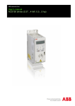
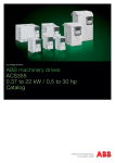
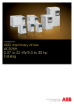
Technical Catalog ABB component drives ACS150, 0.5 to 5 hp Contents Choice 1: Simply contact your local ABB drives sales office and let them know what you want. Use page 4 as a reference section for more information. Type code 1 2 3 4 5 6 7 2 OR ACS150 Product series Ratings and Types Voltages Construction (number of phases for power) Dimension Options Technical Data Control connections Choice 2: Build up your own ordering code using the simple 7-step approach below. Then, contact your local ABB Drives sales office. - 01U - 02A4 - 2 ABB Component Drive, ACS150 ABB Component Drives............................................................. 4 Features..................................................................................... 4 Technical Specification............................................................... 5 Output current rating ................................................................. 6 Input voltage rating..................................................................... 6 Phases....................................................................................... 6 Electro Magnetic Compatibility (EMC)........................................ 6 Dimensions................................................................................. 6 FlashDrop................................................................................... 7 NEMA 1 kit.................................................................................. 7 Brake resistors........................................................................... 8 Cooling....................................................................................... 8 Fuse selections.......................................................................... 8 Connection examples................................................................. 9 1 2 3 4 5 6 7 7 9 3 ABB Component Drives ACS150 - 01U - 02A4 - 2 What is the ACS150 customer value? Dramatically reduced programming time and costs - Replicate parameters in seconds with no power to the drive with new FlashDrop technology - Pre-configure drives prior to delivery - Replicate parameter sets across machines - Hide selected parameters - Spare drives are configured Optimal installation layout with unified height and depth for all frames. Reduced cost with built-in brake chopper and EMC filter Reduced wiring time and costs for I/O and quick, simple and easy access control connections The ABB component drives meet the requirements of OEMs, system integrators and panel builders. It is a component that is bought together with other components. The drive is stocked, and the number of options and variants are optimized for distribution. Highlights FlashDrop- easy to set and select parameters without power Integral operator interface - clear display with buttons Integral potentiometer for frequency setting Integrated EMC filter for 2nd environment Built-in brake chopper as standard Coated boards as standard Unified height and depth NEMA 1 Kit Flexible installation RoHS (verify label) Applications Fans Pumps Gate control Material handling Conveyors Where can it be used? ABB component drives are designed to meet the requirements of an extensive range of machinery applications. The drive is ideal for food and beverage, material handling, textile, printing, rubber and plastics and woodworking applications. What are the ACS150's main features and benefits supporting customer value? 4 Features Benefits Notes FlashDrop Easy and time-saving. Cost-saving for machine builders. Fast and trouble free parameter set up without power. Fixed interface Integrated non-removable control panel. Clear LCD display with backlight and buttons. Simple to use Fixed potentiometer Integrated potentiometer. Settings shown on the control panel Easy speed setting. Built-in EMC filter No extra space, parts, time and cost required 2nd environment built in filter complying with IEC61800-3 as standard Built-in brake chopper Reduced cost. Gives freedom to choose the resistor supplier. 100% braking capability. Flexible installation All units fit in the same sized cabinet Unified height and depth for all frame sizes for optimal use of cabinet space. Sideways, side by side and DIN-rail mounting configuration Coated boards Longer lifetime in hostile environments. Reduced service. Protection against moisture and hostile particles as standard Technical Specification ACS150 - 01U - 02A4 - 2 Input power connection Voltage and power range Frequency Power factor 1-phase, 200 to 240 V ±10% 0.37 to 2.2 kW (0.5 to 3 hp) 3-phase, 200 to 240 V ±10% 0.37 to 2.2 kW (0.5 to 3 hp) 3-phase, 380 to 480 V ±10% 0.37 to 4 kW (0.5 to 5 hp) 48 to 63 Hz 0.98 Motor connection Voltage 3-phase, from 0 to Usupply Frequency Continuous loading capability 0 to 500 Hz Rated output current I2N Overload capability At heavy duty use 1.5 x I2N for 1 minute every 10 minutes At start 1.8 x I2N for 2 s (constant torque at a max. ambient temperature 40oC) (at a max. ambient temperature of 400C) Switching frequency Default Selectable Acceleration time Deceleration time Braking 4 kHz 4 to 12 kHz with 4 kHz steps (16 kHz, v1.31b+) 0.1 to 1800 s 0.1 to 1800 s Inbuilt brake chopper standard (100% braking capability) Environmental limits Ambient temperature Altitude Output current Relative humidity Protection class Enclosure color Contamination levels Storage Transportation Operation -10 to 40oC (14 to 104oF), no frost allowed, 50oC (122oF) with 10% derating Rated current available at 0 to 1000 m (0 to 3281 ft) reduced by 1% per 100 m (328 ft) over 1000 to 2000 m (3281 to 6562 ft) Lower than 95% (without condensation) IP 20 / Protected Chassis NCS 1502-Y, RAL 9002, PMS 420 C IEC721-3-3 No conductive dust allowed Class 1C2 (chemical gases) Class 1S2 (solid particles) Class 2C2 (chemical gases) Class 2S2 (solid particles) Class 3C2 (chemical gases) Class 3S2 (solid particles) Programmable control connections One analog input Voltage signal Current signal Resolution Accuracy Potentiometer reference Auxiliary voltage Five digital inputs Input impedance One relay output Type Maximum switching voltage Maximum switching current Maximum continuous current 0 (2) to 10 V, Rin > 312 kΩ 0 (4) to 20 mA, Rin = 100 Ω 0.1 % ±1% 10V ±1% max, 10 mA R< 10 kΩ 24 V DC ±10%, max. 200 mA 12 to 24 V DC with internal or external supply, PNP and NPN, pulse train 0 to 16 kHz. 2.4 kΩ NO + NC 250 V AC/30 V DC 0.5 A/30 V DC; 5 A/230 V AC 2 A rms Product compliance Low voltage Directive 73/23/EEC with supplements Machinery Directive 98/37/EC EMC Directive 89/336/EEC with supplements Quality assurance system ISO 9001 Environmental system ISO 14001 UL, cUL, and CE approvals, C-Tick, GOST-R EMC (according to EN61800-3) 2 environment filter, unrestricted distribution with 30 m (98 ft) cable, built-in as standard. nd EMC standards in general EN 61800-3/A11 (2000), product standard EN 61800-3 (2004), product standard EN 55011, product family standard for industrial, scientific and medical (ISM) equipment 1st environment, unrestricted distribution 1st environment, restricted distribution 2nd environment, unrestricted distribution) 2nd environment, restricted distribution Category C1 Group 1 Class B Category C2 Group 1 Class A Group 2 Class A Category C3 Category C4 Not applicable 5 Ratings, Types, Voltages and Construction ACS150 - 01U - 02A4 - 2 Type code Type code This is a unique reference number that clearly identifies the drive by power rating, voltage, and construction. Once you have selected the type code, the frame size can be used to determine the drives dimensions, shown below. Voltages Frame size Ratings PN hp PN kW I2N A 1-phase supply voltage 200 - 240 V units ACS150-01U-02A4-2 R0 0.5 0.37 2.4 ACS150-01U-04A7-2 R1 1 0.75 4.7 ACS150-01U-06A7-2 R1 1.5 1.1 6.7 ACS150-01U-07A5-2 R2 2 1.5 7.5 ACS150-01U-09A8-2 R2 3 2.2 9.8 3-phase supply voltage 200 - 240 V units The ACS150 is available in two voltage ranges: 2 = 200 - 240 V 4 = 380 - 480 V Construction ACS150-03U-02A4-2 R0 0.5 0.37 2.4 ACS150-03U-03A5-2 R0 0.75 0.55 3.5 ACS150-03U-04A7-2 R1 1 0.75 4.7 ASC150-03U-06A7-2 R1 1.5 1.1 6.7 ACS150-03U-07A5-2 R1 2 1.5 7.5 ACS150-03U-09A8-2 R2 3 2.2 9.8 3-phase supply voltage 380 - 480 V units "01U" and "03U" within the type code indicates the number of phases for power. 01 = 1-phase (200 - 240V only) 03 = 3-phase (200 - 240V and 380 - 480V) U = EMC filter disconnected, 60 Hz motor data (In case the filter is required it can easily be connected.) ACS150-03U-01A2-4 R0 0.5 0.37 1.2 ACS150-03U-01A9-4 R0 0.75 0.55 1.9 ACS150-03U-02A4-4 R1 1 0.75 2.4 ACS150-03U-03A3-4 R1 1.5 1.1 3.3 ACS150-03U-04A1-4 R1 2 1.5 4.1 ACS150-03U-05A6-4 R1 3 2.2 5.6 ACS150-03U-08A8-4 R1 5 4 8.8 Dimensions, weight and noise Frame Size 1) H2 (in) H3 (in) W (in) D (in) Weight (lbs) 2.4 Noise level dBA 50 R0 6.65 7.95 9.41 2.76 5.59 R1 6.65 7.95 9.41 2.76 5.59 2.9/2.61) 60 R2 6.65 7.95 9.41 4.13 5.59 60 3.3 UN=200...240 V: 1.3 kg / 2.9 lb, UN=380...480 V: 1.2 kg / 2.6 lb Frame Size 2) H1 (in) H4 (in) H5 (in) W (in) D (in) Weight (lbs) Noise level dBA R0 10.12 11.02 2.76 5.59 3.3 50 R1 10.12 11.02 2.76 5.59 3.7/3.52) 60 R2 10.12 11.10 4.13 5.59 4.2 60 UN=200...240 V: 1.7 kg / 3.7 lb, UN=380...480 V: 1.6kg / 3.5 lb NOTES: H1 = Height without fastenings and clamping plate. H2 = Height with fastenings but without clamping plate. H3 = Height with fastenings and clamping plate. H4 = Height with fastenings and NEMA 1 connection box. H5 = Height with fastenings, NEMA 1 connection box and hood. W = Width D = Depth 6 Cabinet-mounted drives (UL open) Wall-mounted drives (NEMA 1) Interface ACS150 - 01U - 02A4 - 2 Removable clip for brand labeling EMC filter grounding screw (EMC) (not pictured) Fixed interface Varistor grounding screw (VAR) (not pictured) FlashDrop connection Analog input signal selector (U/I) Input, brake resistor and motor connections Fixed potentiometer I/O connections Options FlashDrop (MFDT-01) NEMA 1 Kit (MUL1-R1) FlashDrop (MFDT-01) is a powerful palm sized tool for fast and easy parameter selecting and setting. This tool can be used to download parameters to a drive in as little as two seconds. Using this tool, it is also possible to hide selected parameters to protect the machine. Only the parameters needed in the application are shown. FlashDrop does not require the drive to be powered. The drives shipping container is also designed to allow use of the FlashDrop tool without removing the drive. The MFDT-01 includes the DrivePM (Drive Parameter Manager) software tool to create, edit and copy parameter sets. DrivePM requirements Windows 2000/XP Free serial port from a PC The NEMA 1 kit MUL1-R1 includes a conduit box and hood for protection against dirt and dust. The MUL1-R1 covers all ACS150 frame sizes. FlashDrop (MFDT-01) ACS150 with MUL1-R1 NEMA 1 kit FlashDrop tool includes FlashDrop DrivePM software on a CD-rom User's manual in pdf-format on the previous CD-rom Cable for connection between the PC and FlashDrop Battery charger 7 Options Selection table Brake resistors Type code All ACS150 drives are configured with a built-in brake chopper capable of 100% braking. By connecting an external resistor you can enable the dynamic braking function. The minimum and maximum resistance and the required power is shown in the table. Ensure the resistor purchased does not exceed the maximum resistance nor is smaller than the minimum resistance. For more information about the selection of brake resistors, see the ACS150 User's Manual (3AFE68576032) and PowerOhm Resistor Inc. Price List (LVDPNPL02U-EN REVC) effective June 1, 2009. Frame Rmin Rmax size ohm ohm 1-phase supply voltage 200 - 240 V units ACS150-01U-02A4-1 R0 70 390 ACS150-01U-04A7-1 R1 40 200 ACS150-01U-06A7-1 R1 40 130 ACS150-01U-07A5-1 R2 30 100 ACS150-01U-09A8-1 R2 30 70 3-phase supply voltage 200 - 240 V units ACS150-03U-02A4-2 R0 70 390 ACS150-03U-03A5-2 R0 70 260 ACS150-03U-04A7-2 R1 40 200 ASC150-03U-06A7-2 R1 40 130 ACS150-03U-07A5-2 R1 30 100 ACS150-03U-09A8-2 R2 30 70 3-phase supply voltage 380 - 480 V units ACS150-03U-01A2-4 R0 310 1180 ACS150-03U-01A9-4 R0 175 800 ACS150-03U-02A4-4 R1 165 590 ACS150-03U-03A3-4 R1 150 400 ACS150-03U-04A1-4 R1 130 300 ACS150-03U-05A6-4 R1 100 200 ACS150-03U-08A8-4 R1 70 110 PBRmax hp kW 0.5 1 1.5 2 3 0.37 0.75 1.1 1.5 2.2 0.5 0.75 1 1.5 2 3 0.37 0.55 0.75 1.1 1.5 2.2 0.5 0.75 1 1.5 2 3 5 0.37 0.55 0.75 1.1 1.5 2.2 4 Technical data Cooling Fuses The ACS150 is configured with cooling fans as standard. The cooling air must be free from corrosive materials and must not be above the maximum ambient temperature of 40oC (50oC with derating). For more specific limits, see the Technical specification - Environmental limits in this catalog. Air flow Frame Heat dissipation 3 3 size W BTU/Hr m /h ft /min 1-phase supply voltage 200 - 240 V units ACS150-01U-02A4-2 R0 25 85 ACS150-01U-04A7-2 R1 46 157 ACS150-01U-06A7-2 R1 71 242 ACS150-01U-07A5-2 R2 73 249 ACS150-01U-09A8-2 R2 96 328 3-phase supply voltage 200 - 240 V units ACS150-03U-02A4-2 R0 19 65 ACS150-03U-03A5-2 R0 31 106 ACS150-03U-04A7-2 R1 38 130 ASC150-03U-06A7-2 R1 60 205 ACS150-03U-07A5-2 R1 62 212 ACS150-03U-09A8-2 R2 83 283 3-phase supply voltage 380 - 480 V units ACS150-03U-01A2-4 R0 11 38 ACS150-03U-01A9-4 R0 16 55 ACS150-03U-02A4-4 R1 21 72 ACS150-03U-03A3-4 R1 31 106 ACS150-03U-04A1-4 R1 40 137 ACS150-03U-05A6-4 R1 61 208 ACS150-03U-08A8-4 R1 94 321 -* 24 24 21 21 -* 14 14 12 12 ) -* ) -* 24 24 21 21 ) -* ) -* 14 14 12 12 ) -* ) -* 13 13 13 19 24 ) -* ) -* 8 8 8 11 14 ) ) *) Frame size R0 with free convection cooling. Free space requirements Enclosure type All frame sizes 8 Space above Space below Space on left/right mm/in mm/in mm/in 75/2.95 Selection table Type code Cooling air flow Type code Standard fuses can be used with the ACS150. Recommended fuse ratings are shown in the table below. 75/2.95 0/0 Frame size IEC Fuses Fuse ) A type* 1-phase supply voltage 200 - 240 V units ACS150-01U-02A4-2 R0 10 gG ACS150-01U-04A7-2 R1 16 gG ACS150-01U-06A7-2 R1 20 gG ACS150-01U-07A5-2 R2 25 gG ACS150-01U-09A8-2 R2 35 gG 3-phase supply voltage 200 - 240 V units ACS150-03U-02A4-2 R0 10 gG ACS150-03U-03A5-2 R0 10 gG ACS150-03U-04A7-2 R1 10 gG ASC150-03U-06A7-2 R1 16 gG ACS150-03U-07A5-2 R1 16 gG ACS150-03U-09A8-2 R2 16 gG 3-phase supply voltage 380 - 480 V units ACS150-03U-01A2-4 R0 10 gG ACS150-03U-01A9-4 R0 10 gG ACS150-03U-02A4-4 R1 10 gG ACS150-03U-03A3-4 R1 10 gG ACS150-03U-04A1-4 R1 16 gG ACS150-03U-05A6-4 R1 16 gG ACS150-03U-08A8-4 R1 20 gG *) According to IEC-60269 standard. UL Fuses Fuse ) A type* 10 20 25 30 35 UL class T UL class T UL class T UL class T UL class T 10 10 15 15 15 20 UL class T UL class T UL class T UL class T UL class T UL class T 10 10 10 10 15 15 25 UL class T UL class T UL class T UL class T UL class T UL class T UL class T Control Connections These connections are shown as examples only. Please refer to the ACS150 User's Manual (3AFE68576032) for more detailed information. ABB Standard macro ACS150 0 - 20 mA Ground the cable screen on the +24 V sourcing end start/ stop const. fwd/ speed 1 rev SCR AI GND +10 V +24 V GND DCOM DI1 DI2 DI3 DI4 DI5 Default I/O connections I 4) I/O connection U 3) 1...10 kohm Alternative connection for AI1. If used, switch IU selector to U (0...10) V voltage signal) 0V DI configuration PNP connected (source) with external power supply SCR Signal cable shield (screen) AI Frequency reference: 0...20 mA GND Analog input circuit common +10V Reference voltage: +10 VDC, max. 10 mA +24V Auxiliary voltage output: +24 VDC, max. 200 mA GND Auxiliary voltage output common DCOM Digital input common DI1 Stop (0) / Start (1) DI2 Forward (0) / Reverse (1) DI3 Constant speed selection DI4 Constant speed selection DI5 Acceleration and deceleration selection 1) 1) 2) Relay connection 5) ROCOM RONC RONO COM Relay output NC No fault [Fault (-1)] NO ACS150 R < 10 kW ramp const. pair sel. speed 1 fwd/ rev start/ stop DI configuration NPN connected (sink) SCR AI GND +10 V +24 V GND DCOM DI1 DI2 DI3 DI4 DI5 I U 1) See parameter group 12 CONSTANT SPEEDS: 2) 0 = ramp times according to parameters 2202 and 2203. 1 = ramp times according to parameters 2205 and 2206. 3) 360 degree grounding under a clamp. 4) Tightening torque = 0.22 Nm / 2 lbf. in. 5) Tightening torque = 0.5 Nm / 4.4 lbf. in. DI3 DI4 Operation (parameter) 0 0 Set speed through intergrated potentiometer 1 0 Speed 1 (1202) 0 1 Speed 2 (1203) 1 1 Speed 3 (1204) ROCOM RONC RONO DIP switch analog inputs ON AI : 0(4) - 20 mA 9 Notes 10 Notes 11 ABB Inc. Low Voltage Drives 16250 W. Glendale Drive New Berlin, WI 53151 USA Phone: (800) 752-0696 Fax: (262) 785-0397 Web: www.abb.us/drives ABB Inc. 2117, 32nd Avenue Lachine, QC H8T 3J1 Phone: (514) 420-3111 ext: 3505 Fax: (514) 420-3138 ACS150-PHTC01U-EN REVE Effective 07/01/2009 Subject to change without notice. Contact us