Transcript
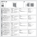
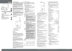
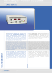
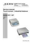
309 092
L
N
t
EIB-Spannungsversorgung
EIB-Power Supply
640 mA
Best. Nr. 907 0 364
8
1
2
L1
N
3
1
1
2
195. . . 255V AC
60 . . . 80 Hz
- 5°C. . .45°C
Diese Betriebsanleitung enthält die erforderlichen
Informationen für den bestimmungsgemäßen
Gebrauch des o. g. Gerätes in einer EIB-Anlage. Für
die Planung und Projektierung der Busgeräte in
einer Installationsbus-Anlage EIB stehen detaillierte
Beschreibungen der Anwendungsprogramme sowie
Unterlagen zur Planungsunterstützung vom
Hersteller zur Verfügung.
Normen und Bestimmungen
Bei der Planung und Errichtung von elektrischen
Anlagen sind die einschlägigen Normen, Richtlinien,
Vorschriften und Bestimmungen des jeweiligen
Landes zu beachten. Arbeiten am Installationsbus
dürfen nur von geschulten Elektro-Fachkräften ausgeführt werden. Verlegung und Anschluss der
Busleitung, sowie der Anwendungsgeräte müssen
gemäß den gültigen Richtlinien unter Beachtung
des Handbuches Gebäude-Systemtechnik der jeweiligen EIBA durchgeführt werden. Die jeweils gültigen Sicherheitsbestimmungen, z.B.
Unfallverhütungsvorschriften, Gesetz über technische Arbeitsmittel, sind auch für die angeschlossenen Betriebsmittel und Anlagen einzuhalten.
Important notes
GB
These operating instructions contain the necessary
information for the correct use of the aforementioned unit in an EIB system. Detailed descriptions of
the user programs and documentation on planning
support by the manifacturer are available for planning and configuring the bus units in an EIB sytem.
I1
2
30V DC
I2
I1 + I2 ≤ 640 mA
ON
7
Adresses, telephone numbers etc. at
www.theben.de
3
I >Imax
Reset
2
Wichtige Hinweise
30V DC
Service
Tel. +49 (0) 90 01 84 32 36
Fax +49 (0) 74 74/6 92-207
hotline@theben.de
e
30V DC
D
Theben AG
Hohenbergstr. 32
72401 Haigerloch
Tel. +49 (0) 74 74/6 92-0
Fax +49 (0) 74 74/6 92-150
1
30V DC
4
5
6
Gefahrenhinweise
– Gerät bei Transport, Lagerung und im Betrieb vor
Feuchtigkeit, Schmutz und Beschädigung schützen
– Gerät nicht außerhalb der spezifizierten
technischen Daten betreiben
– Nur im geschlossenen Gehäuse (Verteiler)
betreiben
– Gerät an den dafür vorgesehenen
Anschlussklemmen erden
– Kühlung der Geräte nicht behindern
Technische Daten
Diese Spannung kann zur Speisung einer Buslinie in
Verbindung mit einer separaten Drossel verwendet
werden.
Stromversorgung
Spannungsbereich
Leistungsaufnahme
Verlustleistung
Ausgänge
EIB-Ausgang
Die EIB-Spannungsversorgung erzeugt und überwacht die EIB-Systemspannung. Mit der integrierten
Drossel wird die Buslinie von der EIB-Spannungsversorgung entkoppelt. Der Anschluss an EIB wird mit
einer Busanschlussklemme hergestellt. Beim Drücken
des Reset-Tasters wird für 20 Sekunden ein Reset ausgelöst (unabhängig davon wie lange der Taster gedrückt bleibt). Die Buslinie wird freigeschaltet und
die an dieser Buslinie angeschlossenen Busteilnehmer werden in den Grundzustand zurückversetzt.
Wird ein längerer Reset benötigt, muss die Busanschlussklemme von der Spannungsversorgung abgezogen werden. Über eine zusätzliche Anschlussklemme wird eine 30 V DC-Hilfsspannung herausgeführt.
EIB-Nennspannung
HilfsspannungsAusgang
HilfsspannungsNennwert
Nennstrom (gesamt)
Safety instructions
– Protect the unit against moisture, dirt and damage
during transport, storage and operation
– Do not operate the unit outside the specified
technical data
– Operate only in a closed housing
(distribution cabinet)
– Earth the unit at the terminals provided
– if existing – for this purpose
– Do not obstruct cooling of the units
Power supply
Voltage range
Power consumption
Power loss
Dauerkurzschlussstrom
Netzausfallüberbrückungszeit
230 V AC, 50 … 60 Hz
195…255 V AC, 45…65Hz
max. 45 VA
max. 6 W
1 Linie mit integrierter
Drossel
30 V DC +/- 2V, SELV
1 (unverdrosselt)
30 V DC +/- 2V, SELV
640 mA, dauerkurzschlussfest (Summe EIBund 30 V-Ausgang)
max. 1,4 A
min. 200 ms
Betriebstemperaturbereich
- 5°C bis + 45°C
Outputs
EIB output
230 V AC, 50 … 60 Hz
195…255 V AC, 45…65Hz
max. 45 VA
max. 6 W
1 line with
integrated choke
EIB rated voltage
30 V DC +/- 2V, SELV
Standards and regulations
Auxiliary voltage
The relevant standards, guidelines, specifications
output
1 (without choke)
and regulations of the country in question must be Technical data
Auxiliary voltage
observed for planning and setting up electrical
The EIB power supply untit produces and monitors the (rated)
30 V DC +/- 2V, SELV
systems. Work on the installation bus may only be
supply voltage for the EIB system. The bus line is
Total rated output
carried out by trained electricians. The bus line and isolated from the power supply by an integrated choke.
current
640 mA, continous short
the units must be installed and connected in
The unit is connected to the EIB via a bus connection
circuit protected (sum of
accordance with the relevant guidelines, observing terminal. When the reset push button is pushed, the
EIB and 30 V outputs)
the EIB user manual Building Systems Engineering
supply voltage is removed and all bus devices are
Short circuit current
max. 1.4 A
of the national EIBA. The relevant safety regulations, returned to their initial state. Once activated, a reset
Mains failure
e.g. accident prevention regulations, law on
lasts for 20 seconds, no matter how long the push but- bridging time
min. 200 ms
technical work equipment, must also be observed
ton is pushed. In case a longer reset is needed, please
for the connected equipment and systems.
Ambient
temperature
-5 °C to +45 °C
disconnect the bus connection terminal. An auxiliary
voltage of 30 V DC is supplied via a second connection Operating and display elements
terminal. This 30 V voltage can be used to feed a
➀ LED green
”ON“: normal operation
second bus line together with an additional choke.
Bedien- und Anzeigeelemente
➀ LED grün
”ON“: Normalbetrieb
➁ LED rot
”I>Imax“: Überlast
bzw
Kurzschluss
➂ Schildertäger
➃ LED rot
Reset am EIB-Ausgang
➄ Reset-Taster
Reset beginnt beim
Drücken des Tasters
und dauert 20s
Schutzart
IP 20 nach EN 60 529
Anschlüsse
➅ EIB-Ausgang
➆ HilfsspannungsAusgang
➇ Stromversorgung
Busanschlussklemme
(schwarz/rot)
Anschlussklemme
(gelb/grau)
3 Schraubklemmen
Anschlussquerschnitt:
feindrähtig 0,2-2,5mm2
eindrähtig 0,2-4,0mm2
Abmessungen
(HxBxT)
Einbautiefe
Breite
90 x 108 x 64 mm
68 mm
6 Module à 18 mm
Gewicht
0,35 kg
➁ LED red
”I>Imax“: overload or
short circuit
➂ Label carrier
➃ LED red
reset status
➄ Reset push button an automatic 20 sec.
reset is activated
when
button is pushed
Protection
Connections
➅ EIB output
IP 20 acc. to EN 60 529
Inbetriebnahme/Betrieb
Inbetriebnahme
Stromversorgung anschließen, LED ”ON“ leuchtet
grün auf. Falls die rote LED ”I>Imax“ aufleuchtet,
Fehlerursache (Kurzschluss oder Überlastung) beseitigen. Danach ”RESET“ durch Drücken des
RESET-Tasters durchführen.
Betrieb: LED ”ON“ leuchtet grün – das Gerät funktioniert ordnungsgemäß (Normalbetrieb). LED
”I>Imax“ leuchtet rot – Fehlerursache (Kurzschluss
oder Überlast) beseitigen. Danach ”RESET“ durch
Drücken des RESET-Tasters durchführen. Wenn
gleichzeitig die LED ”ON“ und die LED ”I>Imax“ aufleuchten, dann ist die Buslinie überlastet, die Ausgangsspannung wird nur kurzzeitig gehalten.
Anzahl der Busteilnehmer reduzieren!
Montage
Zum Einbau in Verteiler. Schnellbefestigung auf
Tragschiene 35 mm, DIN EN 50 022. Der EIBAnschluss erfolgt mit Busanschlussklemme. Der
zusätzliche 30 V-Anschluss erfolgt ebenfalls mit
einer Anschlussklemme. Der Anschluss der
Stromversorgung erfolgt über Schraubklemmen.
Anschlussquerschnitt: feindrähtig 0,2 - 2,5 mm2
eindrähtig 0,2 - 4,0 mm2
Commissioning/Operation
Commissioning:
Connect the EIB power supply to the 203 V mains
sypply. The green ”ON“ LED should light. In case the red
”I>Imax“ LED lights, first remedy the cause of the fault
(short circuit or overload). Then reset the bus line by
pushing the reset button.
Operation: The green ”ON“ LED is on – the unit is operating properly (normal operation). The red ”I>Imax“ LED
is on – first remedy the cause of the fault (short circuit
or overload). Then reset the bus line by pushing the
reset button. Should both the ”ON“ LED and the
”I>Imax“ LED light, the bus line is overloaded and bus
voltage can be maintained for only a short period of
time. Please reduce the number of bus participants!
bus connection terminal
(black/red)
➆ Auxiliary voltage connection terminal
output
(yellow/grey)
➇ Mains
3 screw terminals
connection cross section:
Mounting
multi-core cable 0.2-2.5mm2 For installation in distribution boards or small enclosures.
single-core cable 0.2-4.0mm2 Snap mounting onto 35 mm mounting rails according to
EN 50 022. The EIB bus connection is made using a bus
Dimension
connection terminal. The 30 V auxilitary voltage connec(h x w x d)
90 x 108 x 64 mm
tion, too, is made using a connection terminal. The
Installation depht
68 mm
mains supply is connected by means of screw terminals.
Width
6 modules at 18 mm each
Connection cross section: multi-core cable 0.2-2.5 mm2
Weight
0.35 kg
single-core cable 0.2-4.0 mm2