1
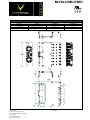
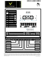
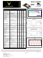
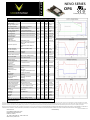
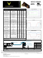
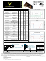
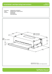
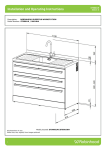
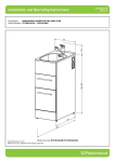
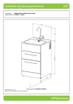
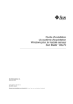
NEV VO+12 200S SSERIESS ‐ Modular ‐ User Configgurable ‐ 1200 Watts of Power NEVO+1200S sseries are moduular and user cconfigurable poower supplies ooffering unriva The lled performan nce and flexibillity. Deliveringg up to 0 watts from a a 1.2kg 6” x 6” x 1U package, the NEVO is the ultimate p power solution for applications where size and weight arre vital 1200 ors. Each systeem consists of aan input modulle with eight slots where any combination o of outputs can bbe fitted to creeate a power soolution facto nd with h up to sixteen isolated outpu uts. The series carry full UL60 0950 2 Editio on safety appro ovals and comp ply with EN61000‐3, EN61000 0‐4 and 50022‐B EMC sstandards. EN55 N FEATURES: MAI 1200 watt outp 1 put at 120VAC 6 6” x 6” x 1U foo otprint H High power den nsity (21W/in3) ) nd E EN60950 2 Ed dition P Primary Side Re emote On/Off High efficien ncy – up to 89% % Only 1.2kg –– 100W/kg I2C control o option Remote current/voltage programming Accurate current sharing Current output siignal 2x 5V 1A bias sup pply Ro oHS compliant Fie eld configurable e Tw wo year warranty SYSTEM M SPECIFICATIO ONS INSTALLATION I INP PUT ELECTRICALL Param meter Details AC Input Voltage e is 100V to 240V Nominal range Contact factorry for 400Hz operation. Standard See graphs for deratings 1200W output at 120Vrms input 265Vrms (cold d start) 5x20 Fast acting AC Input Frequency S i g n a l s DC Input Voltage Powe er Rating Inputt Current Inrush h Current Fusing Inputt Current Limit Efficie ency Idle P Power Idle P Power Stand dby Power Powe er Factor Holdu up UVLO O Over temperature Reliab bility Output Bias voltage Output Bias current Power Good voltage Power Good current Inhibit voltage Inhibit current Global inhibit voltage Global inhibit current AC_OK voltagee AC_OK current AC_OK warningg Primary Bias voltage Primary Bias current Primary Remotee On/Off Min 85 47 17 78 115 4.8 0 8 0 14 86 46 32 2.5 0.99 20 5 10 2 0.2 3 Units 264 Vrmss 63 Hz 370 1200 Vdc Wattts Amps Amps Amps Amps % Wattts Wattts Wattts 40 12.5 PNP open collector with internal 10k pull down n resistor Max 12 Hiccup type ccurrent limit 10k ohm input impedance 50/ 60 120 See graphs All outputs fittted and enabled All outputs fittted and Disabled Latched off state, 120Vrms 1200W output at 120Vrms input Turn on only Internally mon nitored. Latching 40°C 80% load d Two isolated B Bias Outputs available Typ 89 0.99 21 84 125 2 mS Vrmss °C FPMH H 5.2 V 1 A 15 V 20 mA 15 1.5 V mA 15 V 5k ohm input impedance 0.6 3 mA High output Low output See user manu ual for exceptions 4.7 0 ‐10 5 5.2 0.1 10 V V mA mS Medically Isolated 4.8 5.2 V 5 Hiccup type cu urrent limit 0.5 A Negative Edgee Triggered, Refer to User Manual 5 V Vox Power Ltd. Unitt 9 Robinhood Business Park Robinhood Road, Balllymount, Dublin 22 Rep.. of Ireland Tel: +353 1 426 49300 b: ww.vox‐powerr.com Web Parameterr Deta ails Equipment class I Installation n category II Pollution d degree 2 Material ggroup IIIb Parameter Detailss Flammaability rating IP Ratingg ROHS Compliaance 94V‐2 IP10 95/EC 2002/9 Indoorr use only RELIABILITY Componen nt Details FAN INPUT d (2 Fans per unit) Mag Lev Std Excluding FA AN See individu ual output datasheets OUTPUT Min Warranty Max Units 3.8 2 FPMH FPMH 1 FPMH 2 Years SAFETY Parameterr Isolation Voltage Isolation Clearance Isolation Creepage Leakage Cu urrent Details Min Input to Ou utput Input to Ch hassis Output to Chassis Output to Output Primary to Secondary (Reinforced) Primary to Chassis (Basic) Primary to Secondary (Reinforced) Primary to Chassis (Basic) 265Vac, 63 3Hz, 25°C Weight Mounting Distributed By: Vac Vac Vdc Vdc 7 mm mm 12 mm 4 MECHANICAL Size Units 2.5 Parameterr Max 4000 1500 250 250 Details 154.5mm (L)) x 152.4 mm (W) x 41.0mm (see diagram m for tolerance detaails) 720 gram +6 60 gram per output module Bottom (see diagram for detailss) 1500 mm uA DATASHEET D A T A S H E E T N NEVO+ +1200 0S SER RIES Max U Units Temperature Humidity Altitude Air Pressure Relative, non‐con ndensing Full power De‐rate input and d outputs at 2.5%/°C Relative, non‐con ndensing ‐40 5 ‐200 54 ‐20 +85 95 5000 106 50 °C % m kPa °C 50 70 °C 5 ‐200 78 95 3000 106 42 61 % m kPa dBA d dBA d Humidity Altitude Air Pressure Noise Level Shock Vibration Unit at idle Unit at full powerr,25°C Measured 1m fro om fan intake 3000 bumps at 10 0G (16ms) half sine wave 1.5G 10 to 200Hz sine wave, 20G forr 15min in 3 axes random vibration n Emissions Emissions Min Temperature O p e r a t i o n EMC E Details AGENCY APPROVALS A Sta andard Deetails Stand dard Radiated electric field Conducted em missions Harmonic Disttortion Flicker & Flucttuation EN55 5011, EN55022, FCC C EN55 5011, EN55022, FCC C EN61 1000‐3‐2 EN61 1000‐3‐3 1000‐4‐2 EN61 (15kV V air, 8kV contact) EN61 1000‐4‐3 (10V/m) EN61 1000‐4‐4 (4kV) EN61 1000‐4‐5 (1kV L‐N, 2 2kV L‐E) EN61 1000‐4‐6 (10V) Radiated RFI Fast Transientt burst Input line surgges Conducted RFFI Power Freq. M Magnetic Field Voltage Dips Le evel A (See Note) B Com mpliant Com mpliant 4 3 4 3 4 EN61 1000‐4‐8 (10A/m) 3 EN61 1000‐4‐11 (EN55024 4) Com mpliant Note: To meet Class B radiated emissio N ons the end user sho ould add ferrites to I/P and O/P cables. Consult Vox Power for details. File ULL60950‐1 2nd editio on, revised Decemb ber 19 9, 2011 IEC 60950‐1:2005 (2n nd Edition); Am 1:20 009 UL6 60950‐1 Parameter Electrostatic d discharge Immunity Immunity S t o r a g e ENVIRON NMENTAL Parameter IEC C/EN60950‐1 CSA A‐C22.2 No. 2n nd edition 609 950‐1A‐07 CE MARK LV VD 73/23/EEC CB certificate and repo ort available on req quest UL: E31648 86 Typical Line Efficiency (Pmax x) 0.90 0.89 0.88 0.87 Effi i Efficiency Efficiency Typical Load Effficiency (220Vrm ms) 0.92 0.90 0.88 0.86 0.84 0.82 0.80 0.78 0.76 0.74 0.72 0.70 0.68 0.66 200 3 300 400 500 600 700 800 900 1000 1100 0.85 0.84 0.83 OP1 OP2 OP3 OP4 100 0.86 OP1 OP2 OP3 OP4 4 0.82 0.81 0.80 1200 80 1 120 130 140 150 160 170 180 190 20 00 210 220 230 240 250 2 260 90 100 110 Output power (W) put Voltage(Vrms) Inp Tempera ature Derating 1400 1200 1200 1000 1000 Output Power (W) p Power (W) ( ) Output Line De erating 1400 800 Derate at 10 0W per Volt below 120Vrrms 600 No Derrating for DC operation 400 200 800 Derate at a 30W per degree celciu us above 50 degree celcius 600 400 200 0 80 100 120 140 16 60 180 Input Vo oltage (RMS) Vox Power Ltd. Unitt 9 Robinhood Business Park Robinhood Road, Balllymount, Dublin 22 Rep.. of Ireland Tel: +353 1 426 49300 b: ww.vox‐powerr.com Web 200 220 240 0 26 60 -20 -10 0 10 20 30 40 0 Ambient Temperature T (Celcius) Distributed By: 50 60 70 DATASHEET D A T A S H E E T N NEVO+ +1200 0S SER RIES MECHANICAL DIMENSIONS AND MOUNTING SCREW WS SCREWS LOCA ATION DETAILS PENETRA ATION TTIGHTENING MOU UNTING M4 x 4 4mm max, inclu uding chassis 0.75 NM OUTPUT MODULES M3 x 5, C Countersink Posi, 16 6 Places Defined byy screw 0.75 NM CHASSIS LID A AND FACEPLATE M3 x 5, C Countersink Posi, 11 1 Places Defined byy screw 0.75 NM M4 (4X) 4mm depth max Vox Power Ltd. Unitt 9 Robinhood Business Park Robinhood Road, Balllymount, Dublin 22 Rep.. of Ireland Tel: +353 1 426 49300 b: ww.vox‐powerr.com Web Distributed By: D A T A S H E E T NEVO N O+1200 0S SER RIES Circuit 1 2 3 Circuit 1 2 3 4 5 6 7 8 9 10 11 12 1 2 3 4 5 6 REF J1 CONNECTOR RS PINOUTS J1 Detailss v 1 6 Livve Earrth Neeutral J2a/b Detailss Pow wer Good Inh hibit Pow wer Good Inh hibit Pow wer Good Inh hibit Pow wer Good Inh hibit Glo obal Inhibit AC C OK +5V V 1A Bias Supply CO OM J6 Common +5V V 500mA Bias Shu ut Down Reserved Reserved Reserved J6 Slot A and E Slot B and F Slot C and G Slot D and H E N L J1 J2a J2b 2 12 1 11 J1 MANUFFACTURER DEETAILS MA AINS INPUT: 3 Pin, B Barrier, 6‐32 Steel SScrews, 0.8 NM or 7 7IN LB Torque Cable 14‐18AWG, 300 0V, 16A, 105°C, use appropriately rated d fork or ring termin nal. GLOBAL SIGNALS: 12 Pin, 2mm, with Fricction Lock, 24‐30 AW WG INP PUT BIAS: OUTPUT SIGNALS: 6 Pin, 1.25mm, with Friction lock, 28‐32 AWG J2a/b J6 Notes d for any connector parts. 1. Direct equivalents may be used 2. All cables mu ust be rated 105°C min, equivalent to UL1015 HOU USING TERMINAL MOLEX MOLEX MOLEX 511101260 510210600 503948051 1 500588000 0 P PART NUMBERING SYSTEM NEVO Power S Series Leakage Currrent NEV VO+1200 S - 1 1 2 2 3 3 4 4 - 0 0 0 Factory Use e Standard USE '0' for unused d slots. Blanking plates will w be inserted at facto ory. Slot A - Outpu ut # Slot H - Outputt # Slot B - Outpu ut # Slot G - Output # Slot C - Outpu ut # Slot F - Outputt # Slot D - Outpu ut # Slot E - Outputt # Contact your Distrib butor or Vox Power fo or special configuratio on requirements. The e factory may allocatte a 3 or 4 digit suffix x to identify such requ uirement. Vox Powe er Ltd. reserves the right to change or improve any part of the specification, electrical orr mechanical design or manufacturing processs without notice. Pleaase consult your local d distributor or contact V Vox Power to ensure that you have the latest specification before using your product. Forr other information relating to the use of thee product please refer tto the latest NEVO useer manual. Vox Power reserves the right to m make changes notice to any of its prod ducts. Vox Power doess not assume any liabiliity arising out of the usse or application of anyy of its products and off any information to th he maximum extent peermitted by law. No liceense, express without n or implied d, by estoppel or otherrwise, to any intellectu ual property rights is grranted by this document or by any conduct o of Vox Power. VOX POW WER DISCLAIMS ALL W WARRANTIES AND REPR RESENTATIONS. IN PAR RTICULAR ALL OTHER W WARRANTIES, CONDITIO ON OR TERMS RELATIN NG TO SUITABILITY, FITTNESS FOR PURPOSE, M MECHANTABILITY OR C CONDITION OF THE PR RODUCTS AND WHETHER EXPRESS OR IMPLIEED BY STATURE OR CO OMMON LAW OR OTHER RWISE ARE EXCLUDED.. C6034 rev 01 Document DOC D A T A S H E E T NEVO SERIES OP1 Patents pending OUTPUT 1 SPECIFICATIONS Initial voltage accuracy Manual Voltage Adjust Load Regulation Line Regulation Cross Regulation Minimum Load Temperature coefficient Ripple and Noise Transient response Turn on rise time Turn on overshoot Turn on delay Current share accuracy Open sense offset Holdup voltage Isolation to ground Over current protection Reverse current protection Short circuit protection (Hiccup mode) Over voltage protection Over Temperature protection Sense cable protection Power Good threshold Current output signal Current limit control Remote voltage control Bias supply Reliability Warranty Wire Size Weight Size ‐0.5 Typ 5 Max 7.5 25 125 Units V A Watts 187.5 Watts OUTPUT 1 POWER PROFILE 10 OVP 9 8 7 Peak power 6 5 4 0.5 50 0.1 0.2 0 % V/turn mV %Vnom %Vnom Watts 0.02 %/°C 0.545 ‐50 ‐0.1 ‐0.2 125 W 3 OCP See graph, < 5 seconds 50% duty cycle Factory set units 11 turn potentiometer Measured at sense terminals Measured at sense terminals Measured at sense terminals Min 1.5 Volts Peak output power Details See table CONTINIOUS POWER 2 1 HICCUP 0 0 5 10 15 20 25 30 Amps 20MHz BW, pk‐pk 25% to 75% load transient at 1A/us Recovery to within 10% of Vset Monotonic 10% to 90% AC to PG En to PG Open sense, voltage offset due to bias currents ‐0.02 1 %Vnom 1 V 100 uS 3.5 0.1 750 20 5 mS %Vset mS mS %Imax 2 %Vnom 1.5 600 15 Each terminal % of rated current 105 % of rated current ‐6 6 250 V V 125 %rated 0 %rated Period Duty cycle Voltage threshold (Measured at sense terminals) 125 3 1 mS % V Latching Internally monitored. Latching Positive Negative Low threshold only ISIG=0.6+IOUT/(IRTD*1.25) ILMT = (VCTRL‐0.6)*IRTD*1.25 VOUT=VSET((1.8‐VCTRL)/0.6) 10mA max 40°C 80% load 60mm x 35mm x 17mm 115 9.5 ‐1 125 2 1 0 4.5 12 5 °C 110 110 V V %Vset %Irated %Irated 300 %Vset 90 0 0 V 5.2 1 2 10 60 V FPMH Years AWG Grams RIPPLE 0.02 0.015 0.01 0.005 Volts Parameter Output voltage range Rated current Average output power Manual trim range 0 -0.005 -0.01 -0.015 -0.02 0 2 4 6 8 10 12 14 16 18 20 uS Notes: All specifications are believed to be correct at time of publication and are subject to change without notice. Vox Power Ltd. reserves the right to change or improve any part of the specification, electrical or mechanical design or manufacturing process without notice. Please consult your local distributor or contact Vox Power to ensure that you have the latest specification before using your product. For other information relating to the use of the product please refer to the latest NEVO user manual. Vox Power reserves the right to make changes without notice to any of its products. Vox Power does not assume any liability arising out of the use or application of any of its products and of any information to the maximum extent permitted by law. No license, express or implied, by estoppel or otherwise, to any intellectual property rights is granted by this document or by any conduct of Vox Power. VOX POWER DISCLAIMS ALL WARRANTIES AND REPRESENTATIONS. IN PARTICULAR ALL OTHER WARRANTIES, CONDITION OR TERMS RELATING TO SUITABILITY, FITNESS FOR PURPOSE, MECHANTABILITY OR CONDITION OF THE PRODUCTS AND WHETHER EXPRESS OR IMPLIED BY STATURE OR COMMON LAW OR OTHERWISE ARE EXCLUDED. Document DOC6002 rev 02 Vox Power Ltd. Unit 9 Robinhood Business Park Robinhood Road, Ballymount Dublin 22, Ireland Tel: +353 1 426 4930, Fax: +353 1 633 5511 Web: ww.vox‐power.com Distributed By: D A T A S H E E T NEVO SERIES OP2 Patents pending OUTPUT 2 SPECIFICATIONS Transient response Turn on rise time Turn on overshoot Turn on delay Current share accuracy Open sense offset Holdup voltage Isolation to ground Over current protection Reverse current protection Short circuit protection (Hiccup mode) Over voltage protection Over Temperature protection Sense cable protection Units V A Watts 225 Watts 0.5 100 0.1 0.2 0 % V/turn mV %Vnom %Vnom Watts 0.02 %/°C 0.954 ‐100 ‐0.1 ‐0.2 OUTPUT 2 POWER PROFILE 20 OVP 18 16 14 12 10 Peak power 8 6 150 W CONTINIOUS POWER OCP Max 15 15 150 Volts ‐0.5 Typ 12 4 2 HICCUP 0 0 2 4 6 8 10 12 14 16 18 Amps 20MHz BW, pk‐pk 25% to 75% load transient at 0.5A/uS Recovery to within 10% of Vset Monotonic 10% to 90% AC to PG En to PG Open sense, voltage offset due to bias currents ‐0.02 %Vnom 1.5 600 15 1.5 V 100 uS 3.5 0.1 750 20 5 mS %Vset mS mS %Imax 2 %Vnom Each terminal % of rated current 1 12.5 250 105 125 V V %rated 0.75 % of rated current Period Duty cycle Voltage threshold (Measured at sense terminals) ‐6 125 3 0 TRANSIENT RESPONSE 1.5 %rated mS % 20 0 -0.75 15 -1.5 10 -2.25 -3 2 5 V -3.75 -4.5 Latching Internally monitored. Latching Positive Negative Low threshold only ISIG=0.6+IOUT/(IRTD*1.25) ILMT = (VCTRL‐0.6)*IRTD*1.25 115 ‐1 18 125 2 1 Amps Initial voltage accuracy Manual Voltage Adjust Load Regulation Line Regulation Cross Regulation Minimum Load Temperature coefficient Ripple and Noise See graph, < 5 seconds 50% duty cycle Factory set units 11 turn potentiometer Measured at sense terminals Measured at sense terminals Measured at sense terminals Min 4.5 Volts Peak output power Details See table V -0.75 -0.55 -0.35 -0.15 0 0.25 0.05 mS °C V V %Vset %Irated %Irated Power Good threshold 90 Current output signal 0 110 Current limit control 0 110 Remote voltage VOUT=VSET((1.8‐VCTRL)/0.6) 0 300 %Vset control Bias supply 10mA max 4.5 5 5.2 V Reliability 40°C 80% load 1 FPMH Warranty 2 Years Wire Size 16 14 10 AWG Weight 60 Grams Size 60mm x 35mm x 17mm Notes: All specifications are believed to be correct at time of publication and are subject to change without notice. RIPPLE 0.04 0.03 0.02 0.01 Volts Parameter Output voltage range Rated current Average output power Manual trim range 0 -0.01 -0.02 -0.03 -0.04 -10 -8 -6 -4 -2 0 2 4 6 8 10 uS Vox Power Ltd. reserves the right to change or improve any part of the specification, electrical or mechanical design or manufacturing process without notice. Please consult your local distributor or contact Vox Power to ensure that you have the latest specification before using your product. For other information relating to the use of the product please refer to the latest NEVO user manual. Vox Power reserves the right to make changes without notice to any of its products. Vox Power does not assume any liability arising out of the use or application of any of its products and of any information to the maximum extent permitted by law. No license, express or implied, by estoppel or otherwise, to any intellectual property rights is granted by this document or by any conduct of Vox Power. VOX POWER DISCLAIMS ALL WARRANTIES AND REPRESENTATIONS. IN PARTICULAR ALL OTHER WARRANTIES, CONDITION OR TERMS RELATING TO SUITABILITY, FITNESS FOR PURPOSE, MECHANTABILITY OR CONDITION OF THE PRODUCTS AND WHETHER EXPRESS OR IMPLIED BY STATURE OR COMMON LAW OR OTHERWISE ARE EXCLUDED. Document DOC6003 rev 02 Vox Power Ltd. Unit 9 Robinhood Business Park Robinhood Road, Ballymount Dublin 22, Ireland Tel: +353 1 426 4930, Fax: +353 1 633 5511 Web: ww.vox‐power.com Distributed By: D A T A S H E E T NEVO SERIES OP3 Patents pending OUTPUT 3 SPECIFICATIONS Turn on rise time Turn on overshoot Turn on delay Current share accuracy Open sense offset Holdup voltage Isolation to ground Over current protection Reverse current protection Short circuit protection (Hiccup mode) Over voltage protection Over Temperature protection Sense cable protection 20MHz BW, pk‐pk 25% to 75% load transient at 0.25A/uS Recovery to within 10% of Vset Monotonic 10% to 90% AC to PG En to PG Open sense, voltage offset due to bias currents 225 Watts 0.5 % V/turn mV %Vnom %Vnom Watts %/°C 1.9 ‐150 ‐0.1 ‐0.2 ‐0.02 150 0.1 0.2 0 0.02 Period Duty cycle Voltage threshold (Measured at sense terminals) OVP 35 30 25 20 Peak power 15 150 W CONTINIOUS POWER 10 5 HICCUP 0 0 1 2 3 4 5 6 7 8 9 Amps 1 %Vnom 1.5 3 V 100 uS 3.5 0.1 750 20 5 mS %Vset mS mS %Imax 600 15 2 %Vnom 105 25 250 V V 125 %rated TRANSIENT RESPONSE % of rated current OUTPUT 3 POWER PROFILE 40 Each terminal % of rated current Units V A Watts OCP Max 30 7.5 150 ‐6 125 3 3.5 0 %rated 12 3 1.5 10 0 8 -1.5 mS % 6 -3 -4.5 V Amps Transient response ‐0.5 Typ 24 Volts Initial voltage accuracy Manual Voltage Adjust Load Regulation Line Regulation Cross Regulation Minimum Load Temperature coefficient Ripple and Noise See graph, < 5 seconds 50% duty cycle Factory set units 11 turn potentiometer Measured at sense terminals Measured at sense terminals Measured at sense terminals Min 9 Volts Peak output power Details See table 4 -6 2 -7.5 Latching Internally monitored. Latching Positive Negative Low threshold only ISIG=0.6+IOUT/(IRTD*1.25) ILMT = (VCTRL‐0.6)*IRTD*1.25 115 ‐1 36 125 2 1 V -9 -0.75 -0.55 -0.35 -0.15 0 0.25 0.05 mS °C V V %Vset %Irated %Irated Power Good threshold 90 Current output signal 0 110 Current limit control 0 110 Remote voltage VOUT=VSET((1.8‐VCTRL)/0.6) 0 300 %Vset control Bias supply 10mA max 4.5 5 5.2 V Reliability 40°C 80% load 1 FPMH Warranty 2 Years Wire Size 20 18 10 AWG Weight 60 Grams Size 60mm x 35mm x 17mm Notes: All specifications are believed to be correct at time of publication and are subject to change without notice. RIPPLE 0.05 0.04 0.03 0.02 Volts Parameter Output voltage range Rated current Average output power Manual trim range 0.01 0 -0.01 -0.02 -0.03 -0.04 -0.05 -10 -8 -6 -4 -2 0 2 4 6 8 10 uS Vox Power Ltd. reserves the right to change or improve any part of the specification, electrical or mechanical design or manufacturing process without notice. Please consult your local distributor or contact Vox Power to ensure that you have the latest specification before using your product. For other information relating to the use of the product please refer to the latest NEVO user manual. Vox Power reserves the right to make changes without notice to any of its products. Vox Power does not assume any liability arising out of the use or application of any of its products and of any information to the maximum extent permitted by law. No license, express or implied, by estoppel or otherwise, to any intellectual property rights is granted by this document or by any conduct of Vox Power. VOX POWER DISCLAIMS ALL WARRANTIES AND REPRESENTATIONS. IN PARTICULAR ALL OTHER WARRANTIES, CONDITION OR TERMS RELATING TO SUITABILITY, FITNESS FOR PURPOSE, MECHANTABILITY OR CONDITION OF THE PRODUCTS AND WHETHER EXPRESS OR IMPLIED BY STATURE OR COMMON LAW OR OTHERWISE ARE EXCLUDED. Document DOC6004 rev 02 Vox Power Ltd. Unit 9 Robinhood Business Park Robinhood Road, Ballymount Dublin 22, Ireland Tel: +353 1 426 4930, Fax: +353 1 633 5511 Web: ww.vox‐power.com Distributed By: D A T A S H E E T NEVO SERIES OP4 Patents pending OUTPUT 4 SPECIFICATIONS Parameter Output voltage range Rated current Average output power Peak output power Initial voltage accuracy Manual Voltage Adjust Load Regulation Line Regulation Cross Regulation Minimum Load Temperature coefficient Ripple and Noise Transient response Turn on rise time Turn on overshoot Turn on delay Current share accuracy Open sense offset Holdup voltage Isolation to ground Over current protection Reverse current protection Short circuit protection (Hiccup mode) Over voltage protection Over Temperature protection Sense cable protection Details See table See graph, < 5 seconds 50% duty cycle Factory set units 11 turn potentiometer Measured at sense terminals Measured at sense terminals Measured at sense terminals 20MHz BW, pk‐pk 25% to 75% load transient at 0.25A/uS Recovery to within 10% of Vset Monotonic 10% to 90% AC to PG En to PG Open sense, voltage offset due to bias currents Min 18 ‐0.5 Typ 48 Max 58 3.75 150 Units V A Watts 225 Watts 0.5 % V/turn mV %Vnom %Vnom Watts %/°C 3.6 ‐300 ‐0.1 ‐0.2 ‐0.02 300 0.1 0.2 0 0.02 1 %Vnom 3 V 100 uS 3.5 0.1 750 20 5 mS %Vset mS mS %Imax 2 %Vnom 1.5 600 15 Each terminal % of rated current 105 % of rated current ‐6 50 250 V V 125 %rated 0 %rated Period Duty cycle Voltage threshold (Measured at sense terminals) 125 3 3.5 mS % V Latching Internally monitored. Latching Positive Negative Low threshold only ISIG=0.6+IOUT/(IRTD*1.25) ILMT = (VCTRL‐0.6)*IRTD*1.25 115 ‐3 66 125 3 2 V °C V V %Vset %Irated %Irated Power Good threshold 90 Current output signal 0 110 Current limit control 0 110 Remote voltage VOUT=VSET((1.8‐VCTRL)/0.6) 0 300 %Vset control Bias supply 10mA max 4.5 5 5.2 V Reliability 40°C 80% load 1 FPMH Warranty 2 Years Wire Size 20 18 10 AWG Weight 60 Grams Size 60mm x 35mm x 17mm Notes: All specifications are believed to be correct at time of publication and are subject to change without notice. Vox Power Ltd. reserves the right to change or improve any part of the specification, electrical or mechanical design or manufacturing process without notice. Please consult your local distributor or contact Vox Power to ensure that you have the latest specification before using your product. For other information relating to the use of the product please refer to the latest NEVO user manual. Vox Power reserves the right to make changes without notice to any of its products. Vox Power does not assume any liability arising out of the use or application of any of its products and of any information to the maximum extent permitted by law. No license, express or implied, by estoppel or otherwise, to any intellectual property rights is granted by this document or by any conduct of Vox Power. VOX POWER DISCLAIMS ALL WARRANTIES AND REPRESENTATIONS. IN PARTICULAR ALL OTHER WARRANTIES, CONDITION OR TERMS RELATING TO SUITABILITY, FITNESS FOR PURPOSE, MECHANTABILITY OR CONDITION OF THE PRODUCTS AND WHETHER EXPRESS OR IMPLIED BY STATURE OR COMMON LAW OR OTHERWISE ARE EXCLUDED. Document DOC6006 rev 01 Vox Power Ltd. Unit 9 Robinhood Business Park Robinhood Road, Ballymount Dublin 22, Ireland Tel: +353 1 426 4930, Fax: +353 1 633 5511 Web: ww.vox‐power.com Distributed By: D A T A S H E E T NEVO SERIES OP5 OUTPUT 5 SPECIFICATIONS Parameter Output voltage range Rated current Rated power Initial voltage accuracy Manual Voltage Adjust Load Regulation Line Regulation Cross Regulation Minimum Load Temperature coefficient Ripple and Noise Transient response (Vset = 5V) Turn on rise time Turn on overshoot Turn on delay Holdup voltage Isolation to ground Over current protection Reverse current protection Short circuit protection (Hiccup mode) Details Each channel Each channel Each channel Factory set units 11 turn potentiometer Measured at sense terminals Measured at sense terminals Measured at sense terminals Min 5 Typ 12 60 ‐1 ‐50 ‐0.1 ‐0.2 1.5 AC to PG En to PG 600 30 Each terminal Hiccup mode only Units V A Watts % V/turn 50 mV 0.1 %Vnom 0.2 %Vnom 0 0.02 2 Watts %/°C %Vset 1 V 100 uS 3.5 0.1 750 40 12 250 130 mS %Vset mS mS V V %rated mS % 0.9 ‐0.02 20MHz BW, pk‐pk 25% to 75% load transient at 1A/uS Recovery to within 10% of Vset Monotonic 10% to 90% Max 15 5 75 1 105 None 30 1 Period Duty cycle Over voltage protection Latching 20 V Over Temperature Internally monitored. 115 125 °C protection Latching Power Good thresholds High and Low window 68 120 %Vset Reliability 25°C, 100% load, Telcordia 1 FPMH Warranty 2 Years Wire Size 20 18 10 AWG Weight 60 Grams Size 60mm x 35mm x 17mm Notes: All specifications are believed to be correct at time of publication and are subject to change without notice. 10.60 TOP Adjust BOTTOM Adjust J5 Dimension with reference to edge of chassis and centre of connector when in Slot A—Slot pitch 18.30mm J5 TOP—Positive Output 16.50 TOP—Negative Output BOTTOM—Negative Output Dimension with reference to top of chassis and centre of connector. BOTTOM—Positive Output 1 J5 5 REF. DETAILS MANUFACTURER HOUSING Circuit Details 1 Top + Sense 2 Top – Sense 3 Open 4 Bottom + Sense 5 Bottom ‐Sense TERMINAL J1 OUTPUT POWER CONNECTOR: 4 Pin, with Friction lock, 20‐24 AWG MOLEX 430250400 430300001 Notes: 1. Terminal and Wire current rating must exceed maximum output current. 2. Direct equivalents may be used for any connector parts 3. All cables must be rated 105°C min, equivalent to UL1015 Vox Power Ltd. reserves the right to change or improve any part of the specification, electrical or mechanical design or manufacturing process without notice. Please consult your local distributor or contact Vox Power to ensure that you have the latest specification before using your product. For other information relating to the use of the product please refer to the latest NEVO user manual. Vox Power reserves the right to make changes without notice to any of its products. Vox Power does not assume any liability arising out of the use or application of any of its products and of any information to the maximum extent permitted by law. No license, express or implied, by estoppel or otherwise, to any intellectual property rights is granted by this document or by any conduct of Vox Power. VOX POWER DISCLAIMS ALL WARRANTIES AND REPRESENTATIONS. IN PARTICULAR ALL OTHER WARRANTIES, CONDITION OR TERMS RELATING TO SUITABILITY, FITNESS FOR PURPOSE, MECHANTABILITY OR CONDITION OF THE PRODUCTS AND WHETHER EXPRESS OR IMPLIED BY STATURE OR COMMON LAW OR OTHERWISE ARE EXCLUDED. Document DOC6014 rev 03 Vox Power Ltd. Unit 9 Robinhood Business Park Robinhood Road, Ballymount Dublin 22, Ireland Tel: +353 1 426 4930, Fax: +353 1 633 5511, Web: ww.vox‐power.com Distributed By: D A T A S H E E T NEVO SERIES OP6 OUTPUT 6 SPECIFICATIONS Parameter Output voltage range Rated current Rated power Initial voltage accuracy Manual Voltage Adjust Load Regulation Line Regulation Cross Regulation Minimum Load Temperature coefficient Ripple and Noise Transient response (Vset = 5V) Turn on rise time Turn on overshoot Turn on delay Holdup voltage Isolation to ground Over current protection Reverse current protection Short circuit protection (Hiccup mode) Details Each channel Each channel Each channel Factory set units 11 turn potentiometer Measured at sense terminals Measured at sense terminals Measured at sense terminals Min 1.8 Typ 3.3 16.5 ‐1 ‐50 ‐0.1 ‐0.2 1.5 AC to PG En to PG 600 15 Each terminal Hiccup mode only Units V A Watts % V/turn 50 mV 0.1 %Vnom 0.2 %Vnom 0 0.02 2 Watts %/°C %Vset 0.5 V 100 uS 3.5 0.1 750 20 5 250 130 mS %Vset mS mS V V %rated mS % 0.3 ‐0.02 20MHz BW, pk‐pk 25% to 75% load transient at 1A/uS Recovery to within 10% of Vset Monotonic 10% to 90% Max 5 5 25 1 105 None 30 1 Period Duty cycle Over voltage protection Latching 8 V Over Temperature Internally monitored. 115 125 °C protection Latching Power Good thresholds High and Low window 68 120 %Vset Reliability 25°C, 100% load, Telcordia 1 FPMH Warranty 2 Years Wire Size 24 22 20 AWG Weight 60 Grams Size 60mm x 35mm x 17mm Notes: All specifications are believed to be correct at time of publication and are subject to change without notice. 10.60 TOP Adjust BOTTOM Adjust J5 Dimension with reference to edge of chassis and centre of connector when in Slot A—Slot pitch 18.30mm J5 TOP—Positive Output 16.50 TOP—Negative Output BOTTOM—Negative Output Dimension with reference to top of chassis and centre of connector. BOTTOM—Positive Output 1 J5 5 REF. DETAILS MANUFACTURER HOUSING Circuit Details 1 Top + Sense 2 Top – Sense 3 Open 4 Bottom + Sense 5 Bottom ‐Sense TERMINAL J1 OUTPUT POWER CONNECTOR: 4 Pin, with Friction lock, 20‐24 AWG MOLEX 430250400 430300001 Notes: 1. Terminal and Wire current rating must exceed maximum output current. 2. Direct equivalents may be used for any connector parts 3. All cables must be rated 105°C min, equivalent to UL1015 Vox Power Ltd. reserves the right to change or improve any part of the specification, electrical or mechanical design or manufacturing process without notice. Please consult your local distributor or contact Vox Power to ensure that you have the latest specification before using your product. For other information relating to the use of the product please refer to the latest NEVO user manual. Vox Power reserves the right to make changes without notice to any of its products. Vox Power does not assume any liability arising out of the use or application of any of its products and of any information to the maximum extent permitted by law. No license, express or implied, by estoppel or otherwise, to any intellectual property rights is granted by this document or by any conduct of Vox Power. VOX POWER DISCLAIMS ALL WARRANTIES AND REPRESENTATIONS. IN PARTICULAR ALL OTHER WARRANTIES, CONDITION OR TERMS RELATING TO SUITABILITY, FITNESS FOR PURPOSE, MECHANTABILITY OR CONDITION OF THE PRODUCTS AND WHETHER EXPRESS OR IMPLIED BY STATURE OR COMMON LAW OR OTHERWISE ARE EXCLUDED. Document DOC6012 rev 02 Vox Power Ltd. Unit 9 Robinhood Business Park Robinhood Road, Ballymount Dublin 22, Ireland Tel: +353 1 426 4930, Fax: +353 1 633 5511, Web: ww.vox‐power.com Distributed By: D A T A S H E E T NEVO SERIES OP7 OUTPUT 7 SPECIFICATIONS Parameter Output voltage range Rated current Rated power Initial voltage accuracy Manual Voltage Adjust Load Regulation Line Regulation Cross Regulation Minimum Load Temperature coefficient Ripple and Noise Transient response (Vset = 5V) Turn on rise time Turn on overshoot Turn on delay Holdup voltage Isolation to ground Over current protection Reverse current protection Short circuit protection (Hiccup mode) Details Top/Bottom channel Each channel Top/Bottom channel Factory set units 11 turn potentiometer Measured at sense terminals Measured at sense terminals Measured at sense terminals Min 1.8/5 Typ 3.3/12 60/16.5 ‐1 Units V A Watts % V/turn 50 mV 0.1 %Vnom 0.2 %Vnom 0 0.02 2 Watts %/°C %Vset 1/0.5 V 100 uS 3.5 0.1 750 20 12/5 250 130 mS %Vset mS mS V V %rated mS % 0.3/0.9 ‐50 ‐0.1 ‐0.2 ‐0.02 20MHz BW, pk‐pk 25% to 75% load transient at 1A/uS Recovery to within 10% of Vset Monotonic 10% to 90% 1 AC to PG En to PG 600 15 Each terminal Hiccup mode only Max 5/15 5 75/25 1 105 None 30 1 Period Duty cycle Over voltage protection Latching 20/8 V Over Temperature Internally monitored. 115 125 °C protection Latching Power Good thresholds High and Low window 68 120 %Vset Reliability 25°C, 100% load, Telcordia 1 FPMH Warranty 2 Years Wire Size 24 22 20 AWG Weight 60 Grams Size 60mm x 35mm x 17mm Notes: All specifications are believed to be correct at time of publication and are subject to change without notice. 10.60 TOP Adjust BOTTOM Adjust J5 Dimension with reference to edge of chassis and centre of connector when in Slot A—Slot pitch 18.30mm J5 TOP—Positive Output 16.50 TOP—Negative Output BOTTOM—Negative Output Dimension with reference to top of chassis and centre of connector. BOTTOM—Positive Output 1 J5 5 REF. DETAILS MANUFACTURER HOUSING Circuit Details 1 Top + Sense 2 Top – Sense 3 Open 4 Bottom + Sense 5 Bottom ‐Sense TERMINAL J1 OUTPUT POWER CONNECTOR: 4 Pin, with Friction lock, 20‐24 AWG MOLEX 430250400 430300001 Notes: 1. Terminal and Wire current rating must exceed maximum output current. 2. Direct equivalents may be used for any connector parts 3. All cables must be rated 105°C min, equivalent to UL1015 Vox Power Ltd. reserves the right to change or improve any part of the specification, electrical or mechanical design or manufacturing process without notice. Please consult your local distributor or contact Vox Power to ensure that you have the latest specification before using your product. For other information relating to the use of the product please refer to the latest NEVO user manual. Vox Power reserves the right to make changes without notice to any of its products. Vox Power does not assume any liability arising out of the use or application of any of its products and of any information to the maximum extent permitted by law. No license, express or implied, by estoppel or otherwise, to any intellectual property rights is granted by this document or by any conduct of Vox Power. VOX POWER DISCLAIMS ALL WARRANTIES AND REPRESENTATIONS. IN PARTICULAR ALL OTHER WARRANTIES, CONDITION OR TERMS RELATING TO SUITABILITY, FITNESS FOR PURPOSE, MECHANTABILITY OR CONDITION OF THE PRODUCTS AND WHETHER EXPRESS OR IMPLIED BY STATURE OR COMMON LAW OR OTHERWISE ARE EXCLUDED. Document DOC6013 rev 02 Vox Power Ltd. Unit 9 Robinhood Business Park Robinhood Road, Ballymount Dublin 22, Ireland Tel: +353 1 426 4930, Fax: +353 1 633 5511, Web: ww.vox‐power.com Distributed By: