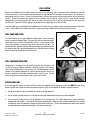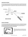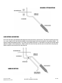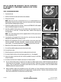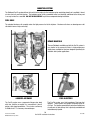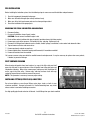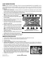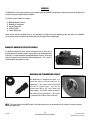
1
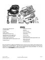
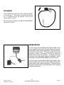
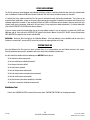
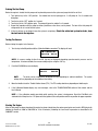
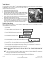
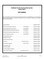
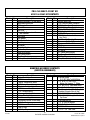
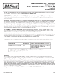
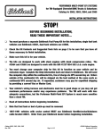
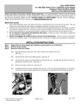
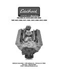
®
TABLE OF CONTENTS
Part #3521 and #3541
Introduction....................................................................................................................1
Components...................................................................................................................2
Preliminaries ..............................................................................................................3-5
Fuel System ...............................................................................................................6-9
Induction System....................................................................................................10-12
Sensors ..................................................................................................................13-14
O2 Sensor Installation...................................................................................................15
Main System Harness .............................................................................................16-20
Ignition System.......................................................................................................21-22
Other Applications....................................................................................................... 23
System Start-Up .................................................................................................... 23-26
Electronic Engine Management ....................................................................................27
Pro-Flo Quick Tuning Guide ..........................................................................................28
Calibration Module Flowchart .......................................................................................29
Parts and Part Numbers..........................................................................................30-31
Service & Warranty ..................................................................................................... 32
INTRODUCTION
Thank you for selecting the Edelbrock Pro-Flo Fuel Injection System. This Multi-Point Fuel Injection System has been designed for
small-block Ford engines, and is designed to provide excellent performance, fuel economy, and maintenance-free operation.
Installation of the Edelbrock/ Pro-Flo Fuel Injection System involves modifications to the fuel system, ignition system, induction
system, and possibly the valve train. Although there are steps that must take place before others, the modifications do not
necessarily have to be performed in a particular order. Each modification is described in a separate section in this manual. Please
study these instructions carefully before beginning installation of any part of the Pro-Flo system.
Calibration Chips:
Important Notice: The Edelbrock Pro-Flo Fuel Injection System is shipped without the computer chip. The chip is necessary
to operate the ECU. If the cam is any brand other than Edelbrock, check with manufacturer for compatibility with EFI. Complete the
Chip Information Card and return to Edelbrock. We will send the computer chip within the continental U.S., free of charge via UPS
second day air. Orders outside of the continental U.S. will be shipped via the best method at the same costs as continental UPS
second day air. If requested, customers may pay for expedited shipping by providing a current Visa or Master Card. The chip installs
into the System Computer in minutes. Additional chips are available for a nominal charge if you decide to change your cam.
Edelbrock has chips for assorted cam profiles. If you have any questions, do not hesitate to call.
If you have any questions, do not hesitate to call our
EFI Technical Hotline at (800) 416-8628, 7am-5pm PST, Monday-Friday
E-mail: EFItech@edelbrock.com
1
Rev. 6/05
Pro-Flo EFI Installation Instructions
Brochure No. 63-0035
©2005 Edelbrock Corporation
COMPONENTS
❑ Electronic Control Unit/System ECU
❑ High pressure fuel pump
❑ Calibration Module
❑ Fuel filter
❑ Distributor
❑ Fuel rail assembly
❑ Ignition amplifier
❑ Fuel pressure regulator
❑ ECU power relay/Fuel pump relay
❑ Fuel injectors
❑ Manifold Absolute Pressure (MAP) Sensor
❑ Intake manifold
❑ Manifold Air Temperature (MAT) Sensor
❑ Four barrel air valve
❑ Coolant Temperature Sensor (CTS)
❑ Idle Air Control (IAC) solenoid, integrated with air valve
❑ Throttle Position Sensor (TPS), integrated with air valve
❑ Main system harness
❑ Oxygen (O2) sensor
❑ Fuel pump harness
❑ Installation package
Many Pro-Flo components, including the Manifold Absolute Pressure sensor, fuel pressure regulator, Coolant Temperature sensor,
and the fuel filter are standard OEM pieces. In the event that one of these parts needs to be replaced, you are likely to find a
replacement at your local parts supplier, in addition to your local Edelbrock dealer or directly from Edelbrock. For a list of part
numbers, refer to the PART NUMBERS section at the back of this manual.
2
Brochure No. 63-0035
©2005 Edelbrock Corporation
Pro-Flo EFI Installation Instructions
Rev. 6/05
TOOLS AND EQUIPMENT
HARDWARE AND PARTS RECOMMENDED
Use the following checklist for items needed.
❑ Box and open end wrenches
❑ Gaskets—Edelbrock, OEM, or equivalent
❑ Pipe plugs, if needed
❑ Socket set
❑ 5/16-inch steel tubing (approximate equal length to fuel
❑ Distributor wrench
pickup line in tank)
❑ Edelbrock Gasgacinch #9300
❑ Pliers (channel locks and hose clamp)
❑ Screwdrivers (regular and Phillips)
❑ Loctite 598 OEM High Temperature Silicone Gasket (O 2
❑ Torque wrench
Sensor Compatible)
❑ Radiator coolant
❑ Hammer
❑ Gasket scraper or putty knife
❑ Teflon tape
❑ Timing light
❑ Intake gasket #3521use Fel-Pro #1250, for #3541use Fel-
❑ Vacuum gauge
❑ Rags
Pro #1250
❑ Wiring diagram for your vehicle
❑ Water bucket
❑ Intake Manifold Bolt kit:
❑ Harmonic balancer puller
#3521 use intake bolt kit #8524
#3541 use Intake bolt kit #8584
❑ Dial indicator
❑ Drill and bits
❑ Hole saw (1 1/4-inch or 1 3/4-inch)
❑ Tubing wrenches
❑ Tubing cutter
P R E L I M I N A RY C H E C K L I S T
1.
CAREFULLY STUDY AND UNDERSTAND ALL INSTRUCTIONS.
2.
Examine the Pro-Flo system for possible shipping damage. If damaged, contact your dealer immediately.
3.
The 3521 kit is designed for use with a standard 302 firing order. If you are running a cam with a 351W firing
order, you must exchange the 3521 wiring harness for the 3541 wiring harness.
4.
The 3541 kit is designed for use with a standard 351W firing order.
5.
The 3521/3541 Pro-Flo kits are supplied with a distributor that is compatible with steel camshafts. If your
camshaft requires a different distributor drive gear, contact MSD at (915) 857-5200. For a small fee, MSD will
exchange the distributor drive gear.
6.
Check all threaded manifold holes.
7.
Check all internal manifold passages with a light and wire, making sure they are clean and unobstructed.
8.
Check automatic transmission shift points before removal of your stock manifold and adjust linkage after
Edelbrock manifold installation for same shift points (if needed).
NOTE:: We recommend that you refer to this checklist again after
installation to be sure that you have completed all steps.
3
Rev. 6/05
Pro-Flo EFI Installation Instructions
Brochure No. 63-0035
©2005 Edelbrock Corporation
DETERMINING HOOD CLEARANCE
NOTE: Check hood clearance before removing stock manifold.
1. Use modeling clay or putty to make five small cones, two or three inches high.
2.
Position cones on air cleaner at front, rear, each side, and on center stud.
3.
Close hood to locked position and re-open.
4.
The height of the cones indicate the amount of clearance between the hood and the air cleaner. Record these
measurements.
CLAY CONE
HOOD CLEARANCE
AIR CLEANER
C
B EA
2-3"
D
D
A
D
AR
RW
AR
RW
FO
FO
C
B E
D
MANIFOLD & CARBURETOR HEIGHT VS. PRO-FLO HEIGHT
HEIGHT B
1. Remove air cleaner.
2. Lay a straightedge (such as a yardstick) across the top of the
carburetor from front to back.
3. Measure from block and manifold end seal surfaces to straightedge.
5. Add height A and height B and divide by two to get the average height.
D
6. The Pro-Flo manifold measures: #3521-A=5.76” by B=5.76” .
The #3541-A=5.76” by B=5.76”. The air valve measures
2.25”.
AR
RW
FO
4. Record these measurements (height A and height B).
HEIGHT A
7. Compare the two measurements. If the Pro-Flo unit is taller, subtract
this amount from the hood clearance figure to determine new hood
clearance.
CAUTION: You must maintain at least 1/2-inch clearance between the hood and air cleaner because of engine torque. If you
have insufficient clearance, a low profile air cleaner may solve the problem.
FUEL REQUIREMENTS
Because the Pro-Flo system uses an Oxygen sensor, you must use unleaded fuel only. Leaded fuels will damage the O2 sensor. If
you do use leaded fuel in your vehicle, do not install the O2 sensor and do not operate the vehicle in the closed loop fuel mode.
EMISSION CONTROLS
The Edelbrock Pro-Flo system will not accept stock emissions control systems. Check local laws for requirements before installing
the Pro-Flo system. Not legal on pollution-controlled motor vehicles.
4
Brochure No. 63-0035
©2005 Edelbrock Corporation
Pro-Flo EFI Installation Instructions
Rev. 6/05
AUTOMATIC TRANSMISSION CHECK
For best performance, economy, and emissions, the shift point must be checked before and after the manifold change.
NOTE: This check should be performed ONLY at a sanctioned drag strip or test track.
With the shifter in Drive, accelerate to wide open throttle from a standing start. Hold in this position, noting speedometer MPH when
the transmission makes the first 1-2 shift. After the Pro-Flo system has been installed, make the same test, again noting MPH of
this first shift.
The transmissions on late model vehicles require precise adjustments. We recommend that you consult a reputable transmission
shop for final adjustments once the Pro-Flo system has been installed. Incorrect shift points can result in transmission damage.
ENGINE CLEANING
Edelbrock recommends that the Pro-Flo system be installed on a clean engine in order to prevent dirt from falling into the engine
lifter valley or intake ports.
1. Cover ignition. Use engine de-greaser and a brush to thoroughly clean the manifold and the area between the manifold and
valve covers.
2. Rinse with water and blow dry.
EXHAUST MANIFOLD HEAT RISER VALVE
If your vehicle is equipped with an exhaust manifold heat riser valve (typically located on the passenger side of the vehicle below the
exhaust manifold), remove the valve for proper operation.
HEADERS
For best performance, headers are recommended. For this application, header primary tube diameter should be 1-3/4 inch,
approximately 31 inches long and terminating into a 3-inch collector. The remainder of the exhaust system should consist of dual
exhaust and tail pipes, at least 2-1/4 inches in diameter with low back pressure mufflers.
COOLING SYSTEM
The minimum requirements for the thermostat are 180° but the ideal thermostat is 195°. When the vehicle is at 175 or below,
system will stay in cold start mode and not perform properly.
5
Rev. 6/05
Pro-Flo EFI Installation Instructions
Brochure No. 63-0035
©2005 Edelbrock Corporation
FUEL SYSTEM
Because your Edelbrock Pro-Flo system controls fuel delivery very differently than a carburetor, some conversions to your fuel
system are necessary. Pro-Flo electronic fuel injection requires high and constant fuel volume and fuel pressure. For this reason, a
good primary fuel line is critical. The Pro-Flo system includes a 3/8-inch high pressure fuel line which must be used as the primary
fuel line. The fuel that bypasses the injectors must be returned to the fuel tank via a return fuel line. If your vehicle is already
equipped with a fuel pump bypass line, this line can be used as the return fuel line. If not, the original primary line may be used as
the return line. If desired, an 8 foot length of 5/16 ID rubber hose is supplied for use as the return line.
Many late-model cars are equipped with an additional fuel line which runs to a charcoal canister mounted on the driver side of the
vehicle. This line MUST be re-installed after the fuel system conversion and MUST NOT be used as the return fuel line.
Tank
Side
FUEL PUMP AND FILTER
The Pro-Flo system uses a single Edelbrock high-pressure electric fuel pump
which is capable of pumping 50 psi. The pump relay will shut down the pump if
it does not receive an engine-run signal from the ECU, as in the case of a stall.
This safety precaution is necessary when using a high-pressure fuel line. The
provided fuel filter should be mounted between the engine compartment and the
fuel pump to allow fuel to be pushed through the filter rather than drawn through.
Electrical connectors should face the front of vehicle.
Engine
Side
FUEL PRESSURE REGULATOR
Fuel pressure is as important as fuel volume, particularly in fuel injection. The
Pro-Flo fuel pressure regulator maintains a constant pressure at the injectors
with a spring loaded by-pass to the return fuel line. Manifold Absolute Pressure
references the regulator diaphragm to maintain constant pressure across all 8
injectors, regardless of fluctuating manifold pressure (vacuum) level. The fuel
that is not injected is returned to the fuel tank via the return fuel line.
RETURN FUEL LINE
Due to the high fuel pressure used by the Pro-Flo system, the supplied 3/8-inch high pressure fuel line MUST be used as the
primary fuel line, and a bypass fuel return line must be installed. There are three options for installing a bypass return line.
1. Use the 5/16 rubber fuel line provided with the system as the fuel return line.
2. Use the vehicle’s existing primary line as the fuel return line with modification to the pick up as described below.
3. Use the vehicle’s existing return line (if so equipped) as the fuel return line. This option applies only to vehicles previously
equipped with fuel injection. If the vehicle is not already equipped with a return line, some fuel tank modifications are required
for routing the return line through the sending unit plate back into the tank. The first two methods listed require some welding
and should be done by a professional radiator or fuel system repair shop.
6
Brochure No. 63-0035
©2005 Edelbrock Corporation
Pro-Flo EFI Installation Instructions
Rev. 6/05
RUBBER RETURN LINE METHOD
Drill a 5/16-inch hole in the sending unit plate adjacent to where the main line enters the tank. This will be the hole for your return
line. Insert a short length of 5/16-inch hard line (available at most radiator shops) into the hole and weld it to the sending unit plate.
The hard line should extend through the hole 1 to 2 inches on each side of the plate. Connect a length (at least 4 inches) of 5/16inch rubber return line hose to the hard line that will extend into the tank. Connect the rubber line to the fuel pickup line using tie
wraps.
RUBBER HOSE METHOD
BULKHEAD FITTING METHOD
Drill a 9/16-inch hole in the sending unit plate adjacent to where the main line enters the tank. This will be the hole for your return
line. Insert a #6 AN bulkhead fitting (available at most radiator shops) into the hole, the narrow end of the fitting on the inside of the
plate. Apply a rubber washer or RTV sealant and fasten the fitting to the plate with the nut. Connect a length (at least 4 inches) of
flexible return line (rubber or braided hose) to the fitting end. Connect the return line to the fuel pickup line using tie wraps.
NOTE: THIS METHOD REQUIRES NO WELDING OF THE FUEL SYSTEM.
NOTE: Whichever method you use to install the return fuel line,
be careful to keep the end of the line away from the fuel pickup,
as shown. Otherwise, aerated return fuel can be drawn into the
pickup.
7
Rev. 6/05
Pro-Flo EFI Installation Instructions
Brochure No. 63-0035
©2005 Edelbrock Corporation
BULKHEAD FITTING METHOD
HARD RETURN LINE METHOD
Drill a 5/16-inch hole in the sending unit plate adjacent to where the main line, enters the tank. This will be the hole for your return
line. Insert a length of 5/16-inch hard line (available at most radiator shops) into the hole and weld it to the sending unit plate. The
hard line should extend through the hole 1 to 2 inches on the outside of the plate. On the inside of the plate, the hard line should
follow the contours of the fuel pickup line. Bend the end of the return line away from the sock on the end of the fuel pickup line.
Solder or weld the return hard line to the fuel pickup line.
HARDLINE METHOD
8
Brochure No. 63-0035
©2005 Edelbrock Corporation
Pro-Flo EFI Installation Instructions
Rev. 6/05
NOTE: ALL WELDING AND SOLDERING OF THE FUEL SYSTEM MUST
BE PERFORMED BY A PROFESSIONAL RADIATOR OR FUEL SYSTEM
REPAIR SHOP.
FUEL SYSTEM INSTALLATION
1. Drain the fuel tank.
2. Remove all fuel lines from the tank and from the carburetor.
3. Remove the fuel tank.
NOTE: While the fuel tank is removed from the car, it is recommended that it be
professionally cleaned in order to remove any rust or dirt that may have accumulated
inside and which could damage the injectors.
4. Remove the sending unit from the fuel tank. Refer to the RETURN FUEL LINE methods
above for installing the bypass fuel return line.
5. Install the provided 3/8-inch primary fuel line directly above the original line, which
may now serve as a return line. Use large radius bends. Avoid the exhaust pipe and
any sharp edges.
NOTE: The 3/8-inch high pressure fuel line supplied with the Pro-Flo system must be
used as the primary fuel line.
6. If you do not use the original fuel as the return line, route the return line directly
alongside the provided 3/8-inch primary fuel line.
7. Mount the fuel pump between the tank and the fuel filter as low and as close to the
fuel tank as possible. The pump is directional. Electrical connectors should face the
front of vehicle. The fuel pump needs to be at or below the level of fuel in the tank.
8. Mount the fuel filter between the fuel pump and the engine.
9. Re-install the modified sending unit plate to the clean fuel tank.
10. Re-install the fuel tank.
11. Attach the primary line and return line to the sending unit plate on the tank.
12. Re-attach all other fuel lines at the tank (vapor purge lines, etc., if so equipped).
13. Secure the primary and return fuel lines with the provided tie-wraps, or with Adel
clamps if available.
14. Re-attach all fuel lines to the induction system once it has been installed.
15.
Use the 10-foot wiring harness to connect the fuel pump to the Main System Harness. Route the harness away from the
exhaust pipe and any sharp edges. This harness may be cut to length. Replacement terminals are provided with the Pro-Flo
system. Cover the connection to the positive terminal with the sleeve and tie wrap provided. Refer to the MAIN SYSTEM
HARNESS section of this manual for details.
16.
Before starting the engine, turn the ignition key to the “ON” position 4 or 5 times to prime the electric fuel pump, fuel lines,
and fuel rails. You should hear the pump run for approximately 2 seconds each time. Check the entire fuel system for leaks.
Refer to the SYSTEM START-UP section of this manual for details.
9
Rev. 6/05
Pro-Flo EFI Installation Instructions
Brochure No. 63-0035
©2005 Edelbrock Corporation
INDUCTION SYSTEM
The Edelbrock Pro-Flo system delivers fuel and air to the engine via the induction system consisting primarily of a manifold, 4-barrel
air valve, fuel rails, and fuel injectors. The induction system is fully assembled, tested, seal checked, and flowed at the factory and
is as easy to install as a manifold. DO NOT DISASSEMBLE any of these components during installation.
FUEL RAILS
The extruded aluminum rail assembly routes the high pressure fuel to the injectors. Aluminum rails have an advantage over soft
rails both in terms of style and safety.
INTAKE MANIFOLD
The new Edelbrock manifold used with the Pro-Flo system is
very similar to the successful Victor Jr. high-performance
single-plane manifold, but has been designed specifically for
electronic fuel injection applications.
#3521
#3541
4-BARREL AIR VALVE
FUEL INJECTORS
The Pro-Flo system uses a progressive linkage valve body
with four throttles arranged in a conventional 4-barrel
pattern, with staged secondaries. The air valve can flow up
to 1000 cfm at 1.5" of mercury when wide open.
The Pro-Flo system uses high impedance Pico-type fuel
injectors. These injectors are capable of flowing 29 lbs./hr.
at 45 psi. The injectors mount directly onto the manifold, one
at each port, for fuel delivery that is precisely controlled and
instantaneously injected.
10
Brochure No. 63-0035
©2005 Edelbrock Corporation
Pro-Flo EFI Installation Instructions
Rev. 6/05
PRE-INSTALLATION
Before installing the induction system, take the following steps to ensure successful installation and performance:
1.
2.
3.
4.
Check all components thoroughly for damage.
Make sure all throttle linkages open entirely and close freely.
Make sure all fuel inlet and vacuum ports are free from packing material.
Check the installation kit for proper parts.
REMOVING THE STOCK CARBURETOR AND MANIFOLD
1. Disconnect battery.
2. For ease of installation, keep all parts in order.
CAUTION: Do not remove manifold if engine is hot.
3. Drain radiator coolant (radiator drain plug is typically located on lower right facing engine).
4. Remove gas cap to relieve pressure. Disconnect fuel line and plug. Replace gas cap.
5. Disconnect all linkage from carburetor such as throttle, throttle springs, transmission, cruise control and automatic choke.
6. Tag and remove coil wires and sensor wires.
7. Remove previously marked vacuum lines.
8. Remove radiator hose, thermostat housing and thermostat, if mounted on manifold.
9. Remove all brackets from the manifold.
10. Loosen or remove valve cover bolts for manifold removal and replacement. It may be necessary to replace valve cover gaskets,
if broken, to prevent oil leakage.
PORT SURFACE CLEANING
When cleaning old gaskets from head surfaces, lay rags in the lifter valley and stuff
paper into the ports, to prevent pieces of the old gasket from falling into ports and
combustion chambers. When clean, remove paper, making sure that all particles fall
on the rags in the lifter valley. Remove rags, and wipe surfaces clean with rags
soaked in lacquer thinner in order to remove oil or grease.
NOTE: This procedure is necessary to ensure proper sealing.
INSTALLING FITTINGS, PIPE PLUGS, AND STUDS
Do not over-tighten or cross-thread fittings, pipe plugs, studs, or bolts in your
aluminum manifold. Damage to threads or a cracked mounting boss may result
unless caution is used when installing accessories.
Use high quality pipe thread sealant on all threads. Install fittings from your stock manifold.
11
Rev. 6/05
Pro-Flo EFI Installation Instructions
Brochure No. 63-0035
©2005 Edelbrock Corporation
GASKET SURFACE PREPARATION
CAUTION: Replace all gaskets as recommended. Do not use race-type non-embossed gaskets for street applications. Due to
material deterioration under street driving conditions, internal vacuum and oil leaks may occur. We recommend Fel-Pro Printoseal
gaskets #1250 or equivalent. Do not use Fel-Pro Permatorque Blue gaskets, which are designed for use on stock cast iron intake
manifolds only.
1. Remove Fuel rails and Injectors: fuel injectors and fuel rails are assembled on the manifold and pressure tested. Installing
the intake requires the removal of both fuel rails. Remove the two 1/4" bolts per fuel rail and flat washers. Carefully remove
one fuel rail at a time and any remaining injectors from intake manifold.
2. Check gaskets on head surface and manifold to make sure they are correct. Embossed side faces up.
NOTE: In some cases, there may be a different right and left
1
9
5
11
3
7
side gasket. Make sure both are placed correctly.
3. Coat head surface and both sides of gaskets with Edelbrock
Gasgacinch #9300.
4. Apply Loctite 598 OEM High Temperature Silicone Gasket
around water passages on head surface.
5. Gaskets and surface will become tacky to the touch within a
few minutes. Carefully place gaskets on head surface,
aligning ports and bolt holes.
6. Edelbrock recommends the use of Loctite 598 OEM High
Temperature Silicone Gasket instead of end seal gaskets.
Apply a 1/4-inch thick bead of sealant across each end seal
surface, overlapping the intake gasket at the four corners.
8
2
6
4
12
10
NOTE: Use the recommended silicon sealer. Others may
BOLT TIGHTENING SEQUENCE
damage the O2 sensor. This method eliminates end seal
Standard 302 Firing order 1-5-4-2-6-3-7-8
slippage and deterioration.
Certain 302’s and 351W’s use 1-3-7-2-6-5-4-8
7. Apply Edelbrock Gasgacinch #9300 to port surface of the
manifold and to the head surfaces to ensure a good seal.
8. Apply RTV gasket sealer around water passages on the manifold.
9. Surfaces will become tacky to the touch within a few minutes.
INDUCTION SYSTEM INSTALLATION
1.
2.
3.
4.
5.
Carefully position manifold and air valve on engine, centering bolt holes with the bolt holes in the head.
Apply thread sealer or Teflon tape to bolt threads where exposed to water or oil.
Hand tighten all bolts.
Torque all manifold bolts to 15-18 ft/lbs. Torque in the sequence as shown.
Install Fuel rails and Injectors: Lubricate injector O-rings (top and bottom) with O-ring type lubricate before sliding them
into fuel rails. Push injectors into rails, making sure that the electrical connectors on injector bodies face up. Place fuel rail
with pressure regulator on passenger's side with regulator toward rear of engine.
Push down with enough force to seat lubricated O-rings in manifold, making sure not
to damage O-rings. Once installed, secure rails with 1/4" bolts and flat washers to 8
ft-lbs( 96 In-lbs). When properly installed, the injectors should rotate freely by hand.
6. Re-connect throttle linkage and springs, transmission, cruise control, and fuel lines.
Check all linkage for smooth throttle operation from idle to Wide Open Throttle.
Note: Do not install with a throttle rod, use a cable actuated throttle.
Throttle rods will cause engine surge as the engine moves in its mounts.
7. Re-tighten the valve cover bolts.
12
Brochure No. 63-0035
©2005 Edelbrock Corporation
Pro-Flo EFI Installation Instructions
Rev. 6/05
SENSORS
The Edelbrock Pro-Flo system interprets overall engine operating conditions and fuel/spark requirements based on readings from
sensors that measure specific engine conditions.
The Pro-Flo system includes five sensors:
1)
2)
3)
4)
5)
Manifold Absolute Pressure
Manifold Air Temperature
Coolant Temperature
Throttle Position
Exhaust Oxygen (O2)
These sensors, with the exception of the O2, are designed as an integral part of the induction system and require no installation.
The O2 sensor must be installed on the exhaust pipe near the engine with a welded fitting.
MANIFOLD ABSOLUTE PRESSURE SENSOR
The Manifold Absolute Pressure sensor, mounted on the air valve with a
bracket, converts air pressure (load) in the manifold, to an analog signal sent
to the ECU. For more information on Manifold Absolute Pressure, refer to the
section on Speed Density Electronic Engine Management. This sensor is
connected to the Main System Harness.
MANIFOLD AIR TEMPERATURE SENSOR
The Manifold Air Temperature sensor, is a
thermistor device which measures air
temperature. This sensor must be installed
i n t o t h e a i r cl e a n e r b a s e . D r i l l t h e a i r
cleaner base with a 3/4” drill, debur any
sharp edges, install MAT sensor grommet,
then slide sensor into grommet. This sensor
is connected to the Main System Harness.
NOTE: The systems that have the MAT sensor in the intake plenum area, can be moved to the air cleaner if necessary to obtain
additional vacuum ports.
13
Rev. 6/05
Pro-Flo EFI Installation Instructions
Brochure No. 63-0035
©2005 Edelbrock Corporation
COOLANT TEMPERATURE SENSOR
The Coolant Temperature Sensor is a thermistor device like the
Manifold Air Temperature sensor. Resistance varies as coolant
temperature rises and lowers. The Coolant Temperature Sensor is
located at the front of the manifold on the passenger’s side, and is
connected to the Main System Harness.
THROTTLE POSITION SENSOR
The Throttle Position Sensor, an integral part of the Pro-Flo
throttle body, measures throttle angle. This sensor requires
adjustment as described in the SYSTEM START-UP section of
this manual. It is connected to the Main System Harness.
OXYGEN (O2) SENSOR
An oxygen sensor, installed on the header collector pipe, measures
exhaust gas oxygen content and is used by the ECU to manage fuel
delivery under closed loop control. Installing the sensor requires
drilling a 1/2-inch hole in the passenger-side header collector. The
sensor is held in place with the provided fitting which must be
professionally welded into place. The red-lean/green-rich light on the
Calibration Module is also controlled by the O2 sensor. The O2 sensor
is connected to the Main System Harness. For installation details, refer
to the FUEL SYSTEM section of this manual.
NOTE: Prior to installing your O2 sensor, check the wires leading into
the weather pack plug and make sure the odd colored wire is
in the middle.
14
Brochure No. 63-0035
©2005 Edelbrock Corporation
Pro-Flo EFI Installation Instructions
Rev. 6/05
O2 SENSOR INSTALLATION
The exhaust gas oxygen content is determined by the oxygen sensor. The sensor signals the ECU, which compensates when the
air/fuel mixture is either rich or lean.
NOTE: It is recommended that the O2 sensor installation be performed by a professional muffler shop.
1. Double check header gaskets, replacing if necessary.
2. Drill a 1/2-inch to 9/16-inch hole in the passenger-side header collector reducer, as close to the header flange as possible
(1" to 3" away).
NOTE: Before drilling, make sure the O2 sensor will be mounted horizontally and within reach of the harness connector. Check
to ensure adequate clearance for the sensor, taking into consideration engine movement.
3. Fit the provided fitting into the hole in the exhaust pipe and weld into place.
4. Once it has been welded into place, clean the threads in the center of the fitting. If your exhaust is coated tap bung threads to
ensure a good ground for the O2 sensor.
5. Thread the O2 sensor into the fitting. A high-heat anti- seize compound has been applied to the sensor threads.
NOTE: The O2 sensor has 18mm x 1.25 spark plug threads.
6. Attach the O2 sensor to the main system harness. Refer to the MAIN SYSTEM HARNESS section of this manual.
NOTE: UNLEADED FUEL MUST BE USED ONCE THE O2 SENSOR HAS BEEN INSTALLED.
COATED HEADERS: Use a digital OHM meter to measure the resistance between cylinder head bolt and the nut of the installed
O2 sensor. The reading should be less than 2 OHMS. If it is more, you need to provide a ground to the O2 sensor mount.
15
Rev. 6/05
Pro-Flo EFI Installation Instructions
Brochure No. 63-0035
©2005 Edelbrock Corporation
MAIN SYSTEM HARNESS
If the ECU is the brain of the Edelbrock Pro-Flo system, the Main System Harness is the central nervous system. Constructed with
SAE grade wires and the most up-to-date Weatherpak connectors, the Main System Harness is a generic harness that can be used
with any application for which the Pro-Flo system is designed.
This diagram illustrates the entire Pro-Flo Main System Harness. Each connector is identified by a alpha-numeric code as listed
below.
Fuel Pump
ECU
White
Ignition Bypass
Ignition Coil
Cal
3521
Fuel Pump
ECU
White
Ignition Bypass
Ignition Coil
Cal
3541
16
Brochure No. 63-0035
©2005 Edelbrock Corporation
Pro-Flo EFI Installation Instructions
Rev. 6/05
INSTALLATION
1. Inspect the Main System Harness, making sure that all connectors and grounds are properly in place.
2. Because the harness extends from the engine compartment into the passenger compartment, a hole must be drilled in the
firewall on the passenger side. Cut two overlapping 1 1/4-inch holes on a 1-inch center in the firewall. Saw the pointed edges
to create an oval-shaped hole.
NOTE: An alternative to this method is to cut a single 1 3/4 inch hole.
3. Extend the fuel pump relay, ECU connector, and Calibration Module relay through the firewall hole into the passenger
compartment.
NOTE: The T-connectors at the joints of the Main System Harness are closed by snap fasteners which can be opened by hand
or with a flathead screwdriver. Once open, the T-connectors can be rotated for ease of installation, if necessary.
4. The 3 1/2 x 2 1/4-inch aluminum plate included on the harness mounts over the firewall hole using four hex head sheet metal
screws.
NOTE: Start the screw holes with a pointed punch or small drill.
5. The wire harness is assembled with the aluminum plate flush against a T-connector. The black plastic casing on the wire
harness can be cut to allow the plate to slide up the harness to the correct location. Once the harness is in place, the casing
should be reattached on both sides of the firewall.
CAUTION: When feeding the wire harness through the firewall, be careful to not damage the wires against the cut sheet metal.
6. A rubber grommet is provided to protect the wires in the aluminum plate. Use RTV to seal the plate to the firewall.
7. Install all connectors according to the list and diagrams. The harness has been designed so that each connector is unique and
will fit only to its correct match. There is only one possible installation combination; it cannot be installed incorrectly.
The Throttle Position sensor attaches to the main harness .
17
Rev. 6/05
Pro-Flo EFI Installation Instructions
Brochure No. 63-0035
©2005 Edelbrock Corporation
The Manifold Absolute Pressure sensor
attaches to the main harness.
The Coolant Temperature sensor attaches to the
main harness.
The Manifold Air Temperature sensor attaches to the
main harness.
Only the fuel injector connectors are identical, but
they are placed in logical sequence. Refer to the
diagram when installing the harness connectors to
the fuel injectors. In addition to the Main System
Harness, the Pro-Flo system includes these shorter
harnesses:
A. IAC to Main System Harness
B. Ignition amplifier to distributor
C. Fuel pump to Main System Harness
18
Brochure No. 63-0035
©2005 Edelbrock Corporation
Pro-Flo EFI Installation Instructions
Rev. 6/05
A.
This IAC connector is part of the main wiring harness and is attached between the Idle Air Control, mounted on the air valve, and
Connector on the Main System Harness.
B.
This 3-foot ignition amplifier wiring harness is attached to the ignition coil with the connector at right side of lower diagram, and at
the ignition amplifier with the connector on the left side of lower diagram. The ground goes to the front of the intake manifold.
Connect the distributor lead to the main harness connector. The 3/8" ring lug must still be grounded properly. The red and brown
wires are routed as follows:
RED: Ignition coil positive (+) terminal +12 start/run also.
BROWN: Ignition coil negative (-) terminal Sleeves and tie-wraps are provided to fit over the terminals once the wires are is
installed.
Factory starter solenoid
White: Edelbrock ignition
power wire
Brown: Factory ignition
bypass Wire
19
Rev. 6/05
Pro-Flo EFI Installation Instructions
Brochure No. 63-0035
©2005 Edelbrock Corporation
C.
The connector on left end (as drawn) of this 10-foot fuel pump wiring harness attaches to connector on the Main System Harness.
The two connectors on the right connect to the positive (+) and negative (-) terminals on the fuel pump. A sleeve and tie-wrap are
provided to fit over the positive terminal once the connector is installed. This sleeve prevents the clamp from shorting the fuel pump
terminals.
The diagram below illustrates how the ignition amplifier, distributor, ignition amplifier wiring harness, and Main System Harness are
connected.
A KEY ON wire (Pink with black stripe) is also included in the Pro-Flo system. This wire connects to the fuse box. Make sure there is
power with the key on and also while cranking.
REFER TO VEHICLE REPAIR MANUAL FOR WIRING DIAGRAM, IF NECESSARY.
RED
BRN
RED
BRN
COIL WIRING HARNESS
RED
BLK
BLK
BRN
PNK
IGNITION COIL
ENGINE GROUND
J29
IGNITION
AMPLIFIER
PNK
BLU
BRN
GRAY
PPL
WHT
FROM MAIN HARNESS
WHT
J26
RED
GRN
PNK/BLK
PPL/WHT
BLK/WHT
BLK
DISTRIBUTOR
FROM MAIN HARNESS
J12
ELECTRONIC CONTROL UNIT /SYSTEM ECU
The Electronic Control Unit (E C U ) must be mounted away from moisture, excessive
heat, or vibration. Underneath the dashboard on the passenger side, or behind the
glove box are recommended locations.
20
Brochure No. 63-0035
©2005 Edelbrock Corporation
Pro-Flo EFI Installation Instructions
Rev. 6/05
IGNITION SYSTEM
DISTRIBUTOR TESTING
1. Install the ECU and wiring harness and make all connections
except the distributor.
2. Disconnect electrical connections at the fuel pump. Unplug the
10-foot fuel pump harness from the Main System Harness. Refer
to the MAIN SYSTEM HARNESS section of this manual for details.
3. Turn the key to the ON position without starting the engine.
Check the Idle Air Control (IAC) solenoid clicks on and off for
approximately 2 seconds.
4. The Pro-Flo Calibration Module will receive power and display an
RPM: 0 reading, among other parameters.
5. Connect the distributor to the wiring harness and spin the
distributor gear by hand. If the distributor sensor is operating properly, the Calibration Module will display an RPM reading
greater than 0. When the distributor stops spinning, the Calibration Module may display NO COMMUNICATION for
approximately 2 seconds. This is normal and indicates that the ECU is waiting for the next distributor signal before the allowed
time expires.
6. If an RPM greater than zero is indicated in step 5, install the distributor.
INSTALLING THE DISTRIBUTOR
1. Install the distributor so that #1 on the cap is positioned where #1 was on your previous distributor.
2. Make sure that the distributor sits completely down on the manifold boss and that the drive gear has fully engaged the oil pump
drive.
3. Lift the rotor by hand to make sure that there is adequate endplay.
Lack of endplay indicates that the rotor shaft is bottomed out on the
oil pump shaft.
4. Lightly tighten the hold down clamp so that the distributor can still be
turned to determine final setting when checking the timing.
5. Re-attach the distributor cap, with the rotor pointing to #1.
6. The distributor is connected to the MAIN SYSTEM HARNESS.
Note: The 3521 kit is designed for use with a standard 302 firing
order. If you are running a cam with a 351W firing order, you must
exchange the 3521 wiring harness for the 3541 wiring harness. The
3541 kit is designed for use with a standard 351W firing order.
#1 position
The 3521/3541 Pro-Flo kits are supplied with a distributor that is
compatible with steel camshafts. If your camshaft requires a
different distributor drive gear, contact MSD at (915) 857-5200. For a small fee, MSD will exchange the distributor drive gear.
21
Rev. 6/05
Pro-Flo EFI Installation Instructions
Brochure No. 63-0035
©2005 Edelbrock Corporation
COIL HARNESS
Install supplied coil harness from coil to ignition amplifier
as seen on page 17. The harness will attach to the coil and
the “B” connector side of the amplifier as seen in the
ignition amplifier section.
Also see the wiring diagram in the MAIN SYSTEM HARNESS
section of this manual.
IGNITION AMPLIFIER
The Pro-Flo system uses the Edelbrock #3518 Ignition Amplifier, which
must be mounted on a flat surface in the engine compartment away from
exhaust headers or other areas that generate heat. The wheel well panel
and firewall are ideal locations. The ignition amplifier features two
connectors, as shown. The connector on the left (A) connects to
Connector J26 on the main system harness. The connector on the right
(B) connects to the 3-foot harness running to the distributor. See the
wiring diagram in the MAIN SYSTEM HARNESS section of this manual.
B
A
The Pro-Flo system uses the Edelbrock #3518 Ignition Amplifier, which
must be mounted on a flat surface in the engine compartment away from
exhaust headers or other areas that generate heat. The wheel well panel
and firewall are ideal locations. The Ignition Amplifier is to be connected
to the Main System Harness.
22
Brochure No. 63-0035
©2005 Edelbrock Corporation
Pro-Flo EFI Installation Instructions
Rev. 6/05
OTHER APPLICATIONS
The Pro-Flo system has been designed and calibrated specifically using the small-block Ford with large-valve style cylinder heads
(such as Edelbrock’s Performer RPM Street Cylinder Heads with 2.02-inch valves) and tubular headers as a baseline.
It is unlikely that every engine on which the Pro-Flo system is installed will match this baseline combination. The system can be
used with similar applications, as long as the correct chip matching your cam profile is installed in the computer and necessary fuel
calibration adjustments are made. If your small-block Ford is not a 302 or 351W, does not have headers, and uses small-valve style
cylinder heads (such as aluminum heads with 1.94-inch valves), it may require more tuning adjustments. For further information
refer to the SYSTEM SET-UP SECTION of the Owner’s Manual.
If you are running small-valve heads and/or you are not using tubular headers, it may be necessary to reduce fuel at WOT from
4000 rpm and up. Refer also to the SYSTEM SET-UP section in the Owner’s Manual. Use the FUEL @ WOT screens (located under
FUEL MODIFIERS) to adjust the fuel at each available RPM.
WARNING: Watch the Rich/Lean light on the Calibration Module. If the light indicates a lean condition (red) for more than a
fraction of a second at 06” vacuum or WOT you are too lean for safe engine operation at full load.
SYSTEM START-UP
Once the Edelbrock Pro-Flo system has been installed, there are a few procedures you must follow to break-in the system.
Carefully performing these break-in procedures will ensure best results and optimal performance.
Use this checklist to double-check the following areas BEFORE starting the car:
❑ Has the battery been reconnected?
❑ Has the radiator been refilled with coolant?
❑ Has the gas tank been refilled?
❑ Has the oil been replaced?
❑ Have all linkages been reconnected?
❑ Have all wiring harness connectors been connected?
❑ Have all fuel lines been reconnected?
❑ Has the exhaust system been completely re-installed?
❑ Has the O2 sensor been installed and connected?
Distributor Test
Refer to the “IGNITION SYSTEM” section of this manual, under “DISTRIBUTOR TESTING” for the proper procedure.
23
Rev. 6/05
Pro-Flo EFI Installation Instructions
Brochure No. 63-0035
©2005 Edelbrock Corporation
Priming The Fuel Pump
Before the engine is started, the fuel pump must be primed to pressurize the system and purge the fuel line of all air.
1. Turn ignition key to the “ON” position. You should hear the fuel pump go on. It will pump for 2 or 3 seconds and
disengage.
2. Turn the key to the “OFF” position for 1 second.
3. Turn the key to the “ON” position again. The pump will go on for another 2 or 3 seconds.
4. Repeat this procedure until the pump has been cycled three or four times, and is primed. The tone of the fuel pump will
change when all air is out of the fuel system.
5. If there is no tone, or no change in tone, the system is not priming. Check the entire fuel system for leaks, from
the fuel tank to the injectors.
Testing The Sensors
Before starting the engine, test all sensors.
1.
Turn the key to the ON position with the Calibration Module connected. The display will read:
RPM: 0 FUEL: 0.0 mS
VAC: 0.0” Hg SPK: 10°
NOTE: A vacuum reading of other than 0.0” Hg may be displayed depending upon barometric pressure and air
temperature. At extreme altitude, the vacuum reading may be as high as 5.0” Hg.
2.
Push the UP ARROW key once to display:
TH2O: 76°F
TAIR: 77°F
TPS: 13°
Volt: 12.0
NOTE:
The water and air temperatures displayed will vary depending on ambient conditions. The system
voltage will vary depending on the condition of the battery.
3.
Move the throttle to test the Throttle Position Sensor (TPS). The TPS reading should vary depending on throttle angle.
4.
If the Calibration Module displays any error messages, refer to the TROUBLESHOOTING section of this manual and the
User’s Manual.
NOTE : If the calibration module goes blank while cranking, the system is losing power. Check the Pink/Black wire
attached to the 3 Amp fuse for +12V power with the ignition in the crank position and the run position for proper operation.
Starting The Engine
After the fuel pump has been primed and the engine has been started, bring the engine speed up to cam break-in RPM (physically
holding the throttle at 2000 to 2500 RPM for 10 to 20 minutes), following the cam break-in procedure as described in the
CAMSHAFT section.
24
Brochure No. 63-0035
©2005 Edelbrock Corporation
Pro-Flo EFI Installation Instructions
Rev. 6/05
Timing Adjustment
Use a timing light to re-time your engine. The following steps must be performed after the induction system has been installed and
the distributor has been re-installed. Refer to the INDUCTION SYSTEM and
IGNITION SYSTEM sections of this manual.
1. Remove spark plug from Number One cylinder.
2. Remove coil wire from distributor and ground it.
3. THIS STEP REQUIRES TWO PEOPLE OR USE OF A REMOTE STARTER SWITCH.
While one person rotates the engine by slowly bumping the starter, the other
holds his finger over the Number One plug hole until compression is felt.
4. Continue to bump starter until timing mark on the crankshaft pulley shows
approximately 10 degrees Before Top Dead Center.
5. Position rotor to approximately align with the Number One cylinder plug wire
terminal in distributor cap. Check that the leading edge of the narrow tooth on
the shutter wheel (as the shutter wheel rotates clockwise) is centered in the
sensor. Refer to the IGNITION SYSTEM section in this manual for details.
Setting Base Spark Advance
After the camshaft has been broken in, the base timing of the engine should be re-set. Use a timing light and the Pro-Flo
Calibration Module to accurately set timing.
1. Start the engine.
RPM: ø FUEL: 0.0 ms
VAC: 0.0"Hg SPK: 10°
2. The Calibration Module screen will display this screen:
<MISC.MODIFIERS>
ENTER to select
3. Press the DOWN ARROW key once to reach this screen:
4. Press the ENTER key to display this screen:
Target Idle RPM:xxxx
EXIT
= SCROLL ENTER
5. Press the UP ARROW key six (6) times until the module displays this screen:
EXIT
Base Tim'g set: OFF
= SCROLL ENTER
6. Press the ENTER key. Press either ARROW key and the screen will display Base Tim’g set: ON.
7. Set the base timing using a timing light and engine running at 1500rpm. Turn the distributor until 10° advance is set.
8. Press the UP ARROW or DOWN ARROW key to turn Base Tim’g set to OFF.
WARNING: DO NOT DRIVE THE VEHICLE WITH THE BASE TIM’G SET ON. SERIOUS ENGINE DAMAGE MAY
RESULT.
NOTE: If you use an advance-type timing light, the degrees advance shown on the Calibration Module (SPRK:) should always
agree with the actual reading at the crank with the timing light.
9. Press the EXIT key. Y ou can now leave this screen using the UP ARROW or DOWN ARROW keys.
25
Rev. 6/05
Pro-Flo EFI Installation Instructions
Brochure No. 63-0035
©2005 Edelbrock Corporation
Idle Adjustment
This procedure is a general recommendation, intended to help you tune up your Pro-Flo® system.
NOTE: In manual transmission cars, this procedure must be followed with the car in Neutral and with the clutch pedal pressed. In
automatic transmission cars, this procedure must be followed with the car in Drive and with the brake pedal pressed.
Idle Calibration Procedure
• Prior to idle calibration, you need to have completed the "System Start-Up" procedure
• Warm up engine to at least 175° f.
Idle Control
• Using the calibration module, Select MISC. MODIFIERS and, Set Idle Control OFF.
Set Idle Mechanical Stop
• Set the mechanical stop screw so that idle speed in park/neutral is 50-100 RPM higher than you want the engine to actually
idle in gear with the idle control turned on. Typically 600 - 1000 RPM depending on the installed cam shaft.
• We find 650 RPM a good idle for our #3522 performer calibration.
Set Throttle Position Sensor
• Loosen the two Throttle Position Sensor (TPS), mounting screws, and rotate the TPS sensor to a setting of 13 degrees as
observed on the Calibration Module.
Set Idle Fuel Modifier and Idle Spark Modifier
• Using the calibration module, Select MISC. MODIFIERS and adjust Idle Spark and fuel Modifiers to obtain best idle quality.
Idle quality will vary with engine design. Fuel and Spark setting will interact, particularly when you approach best settings.
• You must establish a smooth idle prior to using Idle Control. Otherwise, the RPM will surge when Idle Control is turned on.
Save Calibration
•
•
•
•
Re-check that the TPS setting is 13 Degrees.
Using the calibration module, Select MISC. MODIFIERS
Set IDLE CONTROL ON. Set TARGET IDLE to the same RPM established by the idle stop screw.
Save calibration settings to “A”
Idle Speed Activity
• Displayed on the calibration module, (Second Data Screen). The displayed value represents the amount of air that is
bypassing the throttle blades of the air valve, Normal values range from 5% to 75%. This ensures that the computer can
increase or decrease the idle air flow to control idle speed.
• If your have established a "good" idle set up, the RPM will remain nearly constant between in-gear and out-of-gear. The Idle
Speed Activity will change 10- 30% as it adjusts the idle speed.
• The value of Idle Activity is 20% when Idle Speed Control is off.
Idle Speed Activity Modifier
• This function is locked out when Idle Control is off as indicated by "XXXX" in the Target idle display on the Calibration Module
Display.
• The Idle Speed Activity Modifier biases the Idle Activity duty cycle, +/50%, this has the effect of changing RPM control loop
response time.
• We recommend that this value be set to zero modification except in extreme cases.
26
Brochure No. 63-0035
©2005 Edelbrock Corporation
Pro-Flo EFI Installation Instructions
Rev. 6/05
Electronic Engine Management
The Edelbrock Pro-Flo system uses the Speed-Density method of electronic engine management, in which fuel and spark
requirements are based on engine speed (RPM) and engine load (manifold pressure and temperature).
The Electronic Control Unit (ECU) receives signals regarding engine speed (from the distributor), and the three load factors consisting
of coolant temperature (ECT), Manifold Absolute Pressure (MAP) and air temperature (MAT). Once the ECU has determined the
engine operating point (RPM and Load factor), it uses tables programmed into it to instantly calculate correct spark advance and
injector pulse width.
A more detailed description of electronic engine management can be found in the Owner’s Manual for your Pro-Flo system. One
possible point of confusion does need to be clarified. The Pro-Flo system displays vacuum rather than the less-familiar manifold
pressure. This vacuum reading is based on the following SAE standard atmosphere:
Barometer Temperature -
29.5 in Hg
77°F
Because of this, the vacuum figures displayed on the Calibration Module may differ from the vacuum indicated by a true vacuum
gauge, particularly at extreme high or low altitudes.
FUEL MODIFIER TABLE
RPM
1000
2000
3000
4000
5000
7000
WOT
6"
LOAD
The Pro-Flo tables come pre-set from factory for the engine
12"
combination that you specified when you ordered your
computer chip. This factory calibration must be altered with
the Calibration Module to optimize performance. The
18"
Calibration Module allows you to modify the fuel and spark
tables at various engine speeds and levels of vacuum. These
1000
SPARK MODIFIER TABLE
tables may be used for recording your modifications to the
RPM
base table with your own fuel pulse width and spark advance
1750
2500
3500
4500
figures. For information on using the Calibration Module to
6000
enter your figures into the Pro-Flo ECU, refer to the
WOT
LOAD
CALIBRATION MODULE section in the Owner’s Manual.
9"
18"
27
Rev. 6/05
Pro-Flo EFI Installation Instructions
Brochure No. 63-0035
©2005 Edelbrock Corporation
PRO-FLO QUICK TUNING GUIDE
These are basic instructions to help in understanding the tuning of your Pro-Flo fuel injection system. For detailed technical
information on tuning your Pro-Flo, see the Pro-Flo Owner’s Manual. This guide has been developed after talking with end users
that are not familiar with the technical information provided in the Owner’s Manual.
This guide is based on our simple graph that shows the 24 fuel cells that you can tune in to result in a clean and powerful
engine. We recommend when you have your Pro-Flo installed, you have the idle tune up completed and then drive the vehicle to
determine what amount of tuning is needed for general driving. If the unit is drivable, this is the method to use for ease of tuning.
On page 6 of this installation manual, there is a fuel grid that can be used as the map on which to locate and then tune any
drivability problems. Simply drive the vehicle and note any areas that have problems. Circle those areas as a baseline.
When circling the area where a problem exists, you are circling the RPM and Vacuum reading that is present when the problem
occurs. Note whether it is running rich (green light) or lean (red light) at each problem area. Once any problem areas have been
located and noted rich or lean, go into the Miscellaneous Modifiers menu and turn off the Closed Loop Fuel, exit, go to Fuel
Modifiers, and then into Global Fuel. Now drive the vehicle and drive back to each problem area. When driving in a problem area,
add or subtract fuel to obtain the smoothest operation at that driving point. Write down the quantity (plus or minus) of fuel required
to achieve a smooth operation. When all the problem areas have been noted, and the amount of fuel required to achieve smooth
operation has been noted at each problem area, you may now do each adjustment one at a time to achieve a complete tune up.
To input this information, you will need to make sure the Closed Loop Fuel is in the OFF position. Go to each area and enter the
information. If you have found a problem that is not exactly in the center of one of the fuel cells, you will still be able to tune the
area by using the Surround and Conquer method for properly managing the fuel curve. Listed below is an example of this method:
Assume that you have found a problem area at 2500 RPM and 15 inches of Vacuum. This is not an area where you can
address the problem directly. In this scenario, we will say the unit is showing a lean condition (red light). In which case,
fuel will need to be added. We will also say that when driving and using the Global Modifier to find the exact amount of fuel
required, it was determined that the amount needed was plus ten percent (+10%). In the Surround and Conquer method,
you will add fuel at the four locations surrounding the problem area. This is shown in the figure below:
ENGINE RPM
1000
2000
3000
4000
5000
VACUUM
(WOT) 0
Problem Area
6
12
X
7000
In this example, tune
by adding 10% fuel at
each area marked by
an “X”, surrounding
the problem area.
X
LEAN
18
X
X
When the required amount of fuel has been added at each surrounding fuel cell, complete the operation by returning to the
Miscellaneous Modifiers menus, and turning the Closed Loop Fuel ON. Press the SAVE key, then the ENTER key. The hand-held unit
will show SAVING IN PROGRESS. Repeat this procedure at each problem area to complete the tune up.
28
Brochure No. 63-0035
©2005 Edelbrock Corporation
Pro-Flo EFI Installation Instructions
Rev. 6/05
POWER ON
WEBER/ EDELBROCK
Pro-Flo EFI System
RPM: 3000 FUEL: 4.0 ms
VAC: 12.0Hg SPK: 36˚
(1-2 second commercial )
UP
DOWN
ENTER/EXIT
CALIBRATION MODULE DIAGRAM
TH20: 180˚ F TPS: 28˚
TAIR: 98˚ F Volt: 14.5
UP
DOWN
UP
DOWN
Idle: 25% RPM: 3000
TPS: 28̊ Target: 950
RPM: 3000 –> •••••••••
VAC: 12.0 –> ••••
(software identification)
ECU: Q1.3 (c) WEBER’ 93f
CAL: EDEL xxxx CM: 1.6
UP / DOWN
< FUEL MODIFIERS >
ENTER to select
< SPARK MODIFIERS >
ENTER to select
UP / DOWN
ENTER/EXIT
UP / DOWN
ENTER/EXIT
SPRK @ ____ 1000: ±0˚
EXIT = scroll ENTER
FUEL @ WOT 1000:±0%
EXIT = scroll ENTER
FUEL @ ____ 1000: ±0%
EXIT = scroll ENTER
SPRK @ WOT 1000: ±0˚
EXIT = (+)
= (-)
FUEL @ 06" 1000: ± 0%
EXIT = scroll ENTER
FUEL @ ____ 2000: ±0%
EXIT = scroll ENTER
SPRK @ 9" 1000: ± 0˚
EXIT = (+)
= (-)
FUEL @ ____ 3000: ± 0%
EXIT = scroll ENTER
SPRK @ 18" 1000: ± 0˚
EXIT = (+)
=( -)
SPRK @ ____ 2500: ±0˚
EXIT = scroll ENTER
UP
UP
UP
ENTER
EXIT
SPRK @ ____ 1750: ±0˚
EXIT = scroll ENTER
ENTER
FUEL @ 12" 1000: ± 0%
EXIT = scroll ENTER
UP
EXIT
DOWN
DOWN
DOWN
DOWN
FUEL @ 18" 1000: ± 0%
EXIT = scroll ENTER
FUEL @ ____ 4000: ± 0%
EXIT = scroll ENTER
Transient Fuel:± 0%
EXIT = scroll ENTER
FUEL @ ____ 5000: ± 0%
EXIT = scroll ENTER
SPRK @ ____ 4500: ± 0˚
EXIT = scroll ENTER
Cold Start Fuel: ± 0%
EXIT = scroll ENTER
FUEL @ ____ 7000: ± 0%
EXIT = scroll ENTER
SPRK @ ____ 6000: ± 0˚
EXIT = scroll ENTER
Global SPRK Mod: ± 0˚
EXIT = scroll ENTER
SPRK @ ____ 3500: ± 0˚
EXIT = scroll ENTER
Global Fuel Mod: ± 0%
EXIT = scroll ENTER
(FROM ANYWHERE IN MENU)
UP / DOWN
< MISC. MODIFIERS>
ENTER to select
SAVE
RESTORE
ENTER/EXIT
Target Idle RPM: 950
EXIT = scroll ENTER
SAVE data set: A/B/C
EXIT = scroll ENTER
Idle Fuel Mod: ± 0%
EXIT = (+)
=(-)
Saving In progress…
Restore In progress…
Saved to data set #A
Press EXIT
Data set #A RESTORED
Press EXIT
UP
DOWN
Idle Spark Mod: ± 0̊
EXIT = scroll ENTER
RESTORE: baseA/B/C
EXIT = scroll ENTER
EXIT
EXIT
Idle SpdActvty: ± 0%
EXIT = (+)
=(-)
EXIT
EXIT
(Return to main menu)
Idle Control: OFF
EXIT = scroll ENTER
(NOTICE: Some values shown represent arbitrary examples)
(DIAGNOSTIC error messages will flash on any screen)
Closed loop fuel: OFF
EXIT = scroll ENTER
Base Ti m’g set: OFF
EXIT = scroll ENTER
Rev limiter RPM: 6750
EXIT = scroll ENTER
29
Rev. 6/05
Pro-Flo EFI Installation Instructions
Brochure No. 63-0035
©2005 Edelbrock Corporation
Edelbrock Pro-Flo Fuel Injection System
#3521/#3541
PART NUMBERS
Many of the components of the Pro-Flo system are available separately. Many are standard OEM parts. In the event that one of
these parts need to be replaced, you are likely to find a replacement at your local parts supplier, in addition to your local Edelbrock
dealer or directly from Edelbrock.
Ignition Amplifier . . . . . . . . . . . . . . . . . . . . . . . . . . . . . . . . . . . . . . . . . . . . . . . .Edelbrock #3518
ECU Power Relay/Fuel Pump Relay . . . . . . . . . . . . . . .GM 14089736 . . . . . . . . . .Edelbrock #3586
Manifold Absolute Pressure Sensor . . . . . . . . . . . . . . .GM 16006835 . . . . . . . . . .Edelbrock #3587
Manifold Air Temperature Sensor (Screw-in) . . . . . . . .GM 25036751 . . . . . . . . . .Edelbrock #3588
Manifold Air Temperature Sensor (Push-in) . . . . . . . . .A/C 12160244 . . . . . . . . . .Edelbrock #3579
Coolant Temperature Sensor . . . . . . . . . . . . . . . . . . .GM 25036979 . . . . . . . . . .Edelbrock #3589
Throttle Position Sensor . . . . . . . . . . . . . . . . . . . . . . . . . . . . . . . . . . . . . . . . . . .Edelbrock #3590
Oxygen (O2) Sensor . . . . . . . . . . . . . . . . . . . . . . . . . . . . . . . . . . . . . . . . . . . . . .Edelbrock #3591
High Pressure Fuel Pump . . . . . . . . . . . . . . . . . . . . . . . . . . . . . . . . . . . . . . . . . .Edelbrock #3594
Fuel Filter . . . . . . . . . . . . . . . . . . . . . . . . . . . . .A/C DELCO GF-482 . . . . . . . . . .Edelbrock #3596
Fuel Pressure Regulator . . . . . . . . . . . . . . . . . . . . . .GM 17107010 . . . . . . . . . .Edelbrock #3584
Fuel Injectors (one) . . . . . . . . . . . . . . . . . . . . . . . . . . . . . . . . . . . . . . . . . . . . . .Edelbrock #3583
Calibration Module . . . . . . . . . . . . . . . . . . . . . . . . . . . . . . . . . . . . . . . . . . . . . . .Edelbrock #3519
Calibration Module Cord/Plug . . . . . . . . . . . . . . . . . . . . . . . . . . . . . . . . . . . . . . .Edelbrock #3571
Idle Air Control Solenoid . . . . . . . . . . . . . . . .Ford FOAE-9F715 B1A . . . . . . . . . .Edelbrock #3599
30
Brochure No. 63-0035
©2005 Edelbrock Corporation
Pro-Flo EFI Installation Instructions
Rev. 6/05
P R O - F L O M U LT I - P O I N T E F I
#3521 & #3541 KIT CONTENTS
Check
Qty.
1
1
1
1
1
1
1
1
1
1
1
1
1
1
1
1
1
Description
Manifold Assembly ( as seen below)
Installation Instructions
EFI Owner’s Manual
Basic ECU
Fuel Filter
Manifold Air Temperature Sensor
and Grommet
Fuel Pump
Cal. Module
Cal. Module Cord
Cord Adapter
Distributor
Coil / Amplifier Harness
Ignition Amplifier
Main Wire Harness
Fuel Pump Harness
Fuel Pump Relay
20 Amp Fuse (installed in Harness)
Check Qty.
1
2
5
1
1
15’
15”
15’
1
12
3
1
14
1
1
1
1
1
Description
Firewall Cover Plate
5/16” Fuel Line Hose Clamps HP
3/8” Fuel Line Hose Clamps
AN #6 45 Deg. Elbow Push Lock
1/4” In X1/4” Out X 5/32” Vacuum Tee
3/8” Push Lock Fuel Line
11/32” PCV Hose
5/16” Rubber Return line Hose
(fuel Safe)
Fuel Filter Adel Mounting Clamp
Tek screws 10-16 x 3/4”
Tek screws 1/4-14 x 3/4”
PCV Valve
11” Tie Wraps
O/2 Sensor
O/2 Sensor Weld In Bung
Fuel Pump Block Off Plate
1/2” Pipe Plug
3 Amp Fuse (installed in Harness)
MANIFOLD ASSEMBLY CONTENTS
(SHIPPED ASSEMBLED)
Check
Qty.
1
1
1
1
8
1
1
1
1
1
1
4
4
1
1
Check
Description
Intake Manifold
7/32” Vacuum Hose
Coolant Temperature Sensor
MAP Sensor Assembly
Electronic Fuel Injectors – Pico
5/32” Vacuum Hose 6”
7/32” Vacuum Hose 8”
Passenger Side Fuel Rail
Driver Side Fuel Rail
Fuel Pressure Regulator
Assembled 4 Barrel Throttle Body
1/4” Star Washer
5/16” Internal Start Washer
Viton O-Ring
3/8” Pipe Plug
Qty.
1
1
1
1
1
1
4
1
4
1
4
4
Description
Fuel Inlet Fitting
(3/8” NPT Male To #6 AN Male)
1/4” In To 1/4” Out X 5/32”
Bottom Out Vacuum “T” Fitting
1/4” NPT To 1/4” Hose Barb, Brass
Throttle Body Gasket
Fuel Crossover line With 45-Deg. End
(Includes Schrader Valve & Cap)
1/4”-20 X 1/2” Hex Head Cap Screw
1/4” -20 X 1.25” Long Hex Head
Cap Screw”
Fuel Regulator Nut
1/4” ID. SAE Flat Washer
1/4” ID. Split Lock Washer
5/16” Hex Nut
5/16 X 1-3/8” Carb Studs
31
Rev. 6/05
Pro-Flo EFI Installation Instructions
Brochure No. 63-0035
©2005 Edelbrock Corporation
SERVICE
In the event that your Edelbrock Pro-Flo System should need servicing, return the unit pre-paid to
the Edelbrock Service and Repair facility at 2700 California Street, Torrance, CA 90503. Do not
attempt to disassemble or service the components of the Pro-Flo system yourself. Doing so may
void the warranty.
WARRANTY
It is the constant endeavor of the Edelbrock Corp. to provide our customers with the highest quality
performance products. Edelbrock warrants the Edelbrock Pro-Flo System to be free from defects in
both workmanship and materials for a period of one year from date of purchase, provided that the
product is properly installed and subjected to normal use and service, is not used for racing or
competition purposes and that the product is not modified or altered in any way unless specified by
our instructions. Our warranty service and repair facility is located at 2700 California Street,
Torrance, CA 90503. Customers requiring warranty assistance should contact the dealer from whom
they purchased the product. In turn, the dealer will contact Edelbrock, and we will determine the
method of satisfying the warranty. Should Edelbrock determine that the product be returned to the
factory, it should be accompanied by proof of purchase and a clear description of the exact problem.
The product must be returned freight pre-paid. If a thorough inspection of the product by the factory
indicates defects in workmanship or material, our sole obligation shall be to repair or replace the
product. This warranty covers only the product itself and not the cost of installation or removal.
EDELBROCK CORPORATION SHALL NOT BE LIABLE FOR ANY AND ALL CONSEQUENTIAL
DAMAGES OCCASIONED BY THE BREACH OF ANY WRITTEN OR IMPLIED WARRANTY
PERTAINING TO THIS SALE, IN EXCESS OF THE PURCHASE PRICE OF THE PRODUCT SOLD.
If you have any questions regarding this product or installation, please contact our Technical
Department from 8:00am-12:30; 1:30-5:00pm, Pacific Standard Time, Monday through Friday at:
Tech Telephone: (800) 416-8628
EFI Tech Fax: (310) 320-3964
Edelbrock Corporation
2700 California Street
Torrance, CA 90503
®
32
Brochure No. 63-0035
©2005 Edelbrock Corporation
Pro-Flo EFI Installation Instructions
Rev. 6/05