1
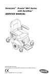
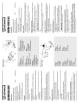
LSI System II
Interferential with Russian Stimulation
Owner’s Manual
KC Metro Area: 913-894-4493
Toll Free: 800-832-0053 • Fax: 866-216-2541
lsiinternational.com
Rev.B OM001 Updated 06/2012
LSI International, a division of Medical Outfitters, LLC
640 Miami Ave
Kansas City, KS 66105-2140
Control Panel
TIMER
FREQUENCY
B
3-5 Hz
1-150Hz
1-15 Hz
2500 Hz
80-120 Hz
C
L
G
A
4000 Hz
SWEEP
SET
N
mA
H
D
F
2
I
START
STOP
O
10/10
10/50
SWEEP
START
STOP
VECTOR
E
J
K
Q
1
REMOTE
STOP
M
1
SET
PREMOD
mA
SYSTEM II
INTERFERENTIAL
R
P
2
S
Features
The LSI System II contains a current test feature which senses the quality of the electrode contact. If your
electrodes
Featuresare making poor contact with the tissue, the unit will emit a beeping tone and the LEDs on the
mA
will drop
to 0 andaflash.
If test
this feature
occurs,which
recheck
your the
electrodes
andthe
lead
wires tocontact.
ensure Ifproper
Theoutput
LSI System
II contains
current
senses
quality of
electrode
your
contact
andare
again
increase
electrodes
making
poorintensity
contact with
with the
the intensity
tissue, thekeypads.
unit will emit a beeping tone and the LEDs on
the mA output will drop to 0 and flash. If this occurs, recheck your electrodes and lead wires to ensure
Aproper
-FREQUENCY
Indicates
frequency
which the
unit is set. Will read actual burst frequency
contact andREADOUT:
again increase
intensity
with theatintensity
keypads.
when in PREMOD mode and will read difference between channel 1 and 2 in frequency difference
(PREMODREADOUT:
light off).. Indicates frequency at which the unit is set. Will read actual burst frequency
A- mode.
FREQUENCY
when in PREMOD mode and will read difference between channel 1 and 2 in frequency difference mode.
(PREMOD light
off).
B -FREQUENCY
SELECTION:
Use the frequency range of your choice. Frequency readout will show top
of range selected prior to activation of SWEEP mode.
B- FREQUENCY SELECTION: Use the frequency range of your choice. Frequency readout will show
top of range selected
of SWEEP
mode.
C -FREQUENCY
ADJUST:prior
Useto
toactivation
set a specific
frequency.
As as example, to set 50 Hz, first set Frequency
Selection at the 1-15 Hz range, then press up the keypad to increase frequency to 50 Hz.
C- FREQUENCY ADJUST : Use to set a specific frequency.
. As as example, to set 50 Hz, first set
Frequency Selection at the 1-15 Hz range, then press up the keypad to increase frequency to 50 Hz.
1
8
D -PREMOD: When off (no light), channel 1 will operate at an uninterrupted 4000Hz and channel 2 will
operate at 4000Hz plus the frequency selected on function A (Frequency Readout). When on (light on),
both channels will operate at a carrier frequency of 4000Hz and both channels will be synchronized to
deliver the frequency as shown in function A.
E -SWEEP: Frequency will sweep between the range indicated in function B ( Frequency Selection).
Press key pad to activate light and this function.
F -SET: This key is used for a special programming option. Please refer to page 10.
G -TIMER: Indicates treatment time remaining. H -TIMER SET: Set key automatically enters 10 minutes to timer.
I -TIME ADJUST: By pressing the up or down key, the treatment time may be raised or lowered from the
10 minutes which is set automatically.
J - START: Activates timer and outputs to channels 1 and 2.
K -STOP: Stops timer and output to channels 1 and 2.
L -MILLIAMPS OUTPUT: Indicates the output, measured in milliamps, which is actually being delivered
to the tissue.
M -CURRENT OUTPUT CONTROLS: Keypads will increase or decrease the delivered current to channels
1 and 2.
N -2500HZ MODE: Automatically activates 50Hz premodulated setting typically used for Russian Stimulation and muscle spasm reduction. When using the 2500Hz setting, SWEEP and VECTOR controls will
be in the off position. For simplification, these features are programmed in a locked off mode.
O -10/10 MODE: Activates the 10 second on and 10 second off function. When activated, the off portion
of the cycle will precede the on portion. Automatic ramping of 2.5 seconds up and 2.0 seconds down is
provided.
P -10/50 MODE: Activates the 10 second on and 50 second off function. When activated, the off portion
of the cycle will precede the on portion. Automatic ramping of 2.5 seconds up and 2.0 seconds down is
provided.
Q -VECTOR: When activated, channel 1 and 2 will alternately drop 20% from their preset output and
return to the preset figure. Notes Concerning Functions M, N, O and P: As a safety feature, output cannot be changed while the
10/10 or 10/50 functions are in the off cycle or when the VECTOR light is on. Also, since there is no reason
to utilize the VECTOR while the 10/10 or 10/50 functions are in use, the unit will not allow dual activation.
R-REMOTE STOP: Depressing the button on the remote control will stop all output of the unit. A repeating
tone will sound, signaling the operator that the patient has activated the switch.
S - OUTPUT JACKS: Output jacks for channel 1 and 2.
***Complete operating instructions with examples are reviewed in the Instructional Video (CD-ROM) provided with your unit.***
2
Special Programming Options
The LSI System II allows for several special programming options.
1- To create a frequency range: (Example: 70 to 100Hz)
a. Select 80 – 120Hz range.
b. Use down arrow on frequency adjust to lower readout to 100Hz, then push SET control in frequency section.
c. 80Hz will now appear in a flashing mode. Use down arrow on frequency to lower readout 70Hz, then
push the set control again.
d. 10 will now flash in the timer section. You can either change the timer with the arrows under the
timer SET control or leave the timer at 10. To set the time selected, again push the SET control in
the frequency section.
When SWEEP and START are activated, the frequency will sweep between 70 and 100Hz. Any range 1Hz
to 250Hz can be established.
2 - To change on and off times and ramp times under the 10/10 and 10/50 controls:
a. S
elect 2500Hz. This will automatically activate the 50Hz premodulated settings. The following
example uses the 10/10 control. The procedure is the same for 10/50.
b. While in the STOP mode, push 10/10 key. 10 and 10 will appear above the mA. This signifies 10
seconds on (left LED) and 10 seconds off (right LED). On and off times can be changed by pressing
up or down arrows. When new on and off times are selected, press 10/10 key again. Now ramp times
are displayed with ramp up on the left LED and ramp down on the right LED. These can be changed
in .5 second increments by using up or down arrows. Push the 10/10 key again. The new times are
now programmed in. Push START, increase mA output to desired contraction, then push 10/10 to
begin on and off sequence.
3 - To program two treatments back to back:
Some clinicians have desired to treat the same area with two different frequencies, one treatment following
the other without resetting the unit. As an example, you may want to treat at 80–120Hz for 6 minutes
followed by 3 – 5 Hz for another 6 minutes. This can be accomplished as follows.
a. Select PREMOD and/or SWEEP functions.
b. Select 1st treatment range (i.e. 80 - 120Hz)
c. Press SET (in frequency adjustment section) to accept 120.
d. The 120 will change to 80 and flash.
e. Press SET again to accept the 80 Hz setting.
f. The 10 will now flash in the timer selection. To lower the time to 6 minutes use the down arrow until 6 appears.
g. Press SET again (in frequency adjustment section). The first treatment of 80 - 120Hz for 6 minutes
has now been entered.
h. Now press the 3 - 5Hz setting.
i. Press SET to accept the 5Hz, 3 will now flash.
j. Press SET to accept the 3Hz, 10 will now flash in the timer section.
k. Push the down arrow under the timer to lower the time to 6 minutes.
l. Press SET again (in the frequency adjustment section) to enter the 6 minute treatment time.
Both treatments have now been stored.
m. Press START and increase the intensity to patient comfort. After the first treatment (80 – 120Hz for
6 minutes) has been completed, the second treatment (3 – 5Hz for 6 minutes) will automatically begin.
3
Caution
1) Never turn the unit on or off (by means of the on/off toggle switch located on the back of the unit) while a patient is attached to the unit via the lead wires and electrodes.
2) Never operate unit during lightening, thunderstorms or any condition that could have an adverse effect on continuity of
power flow to the unit.
3) Never operate unit in close proximity to any type of diathermy device.
4) Federal law restricts this device to the use or sale to a physician or other practitioner in the state or
province in which said person is licensed and practices.
5) Do not use this device when treating electrically susceptible patients such as those with pacemakers, etc.
6) Use extreme caution when treating areas of impaired sensory response or patients unable to report discomfort and pain.
7) Do not apply electrodes transthoracically, in the vicinity of the eyes, carotid sinus nerves or transcerebrally.
8) This device is not recommended for patients who are pregnant or who suffer from heart disease.
9) This device should not be used to relieve chronic pain until etiology has been established.
10) Application of electrical stimulation can produce irritations at the stimulation site. This may be caused by the electrodes, or other media in contact with the skin. Determine the cause of the irritation and replace the item as necessary.
11) Electrical stimulation should only be applied with an effective coupling medium. LSI recommends the use of LSI Silver
Tab Electrodes included with your unit.
12) E
lectrical stimulation is contraindicated in the case of malignant tumors, cancerous lesions, acute or severe inflammation, circulatory insufficiency or the danger of hemorrhage.
13) Do not use simultaneously in the same treatment area with cold packs or heat therapy, either wet or dry.
14) Keep this device out of the reach of children.
15) Do not use in general area where high powered frequency transmitting units are being operated.
16) Shortwave diathermy should not be turned on or used at the same time, as it may interfere with the proper operation of
the LSI System II Interferential.
17) Do not use the same power outlet or line with whirlpool, traction machines, and any other heavy electrical machines
or motors.
18) This unit requires a grounded outlet. If you have any doubts as to the quality of the electrical wiring in your clinic,
please have it checked and verified by a professional.
NOTE: In order to ensure proper and safe operation of your
LSI unit, it is absolutely necessary that only LSI DIN PIN
leadwires like those supplied with this unit be used.
4
IMPORTANT
The most common operational problems associated with electrotherapy
devices center around the lead wires and electrodes.
Please read the following information concerning these components.
Electrode and Lead Wire Test Mode
To test for defective lead wires and/or electrodes follow this procedure:
a. Hold down the STOP key for 5 seconds, until all 8s appear in the Frequency section, 10 appears
above Time and 01 appears in both channel 1 and channel 2 output.
b. Plug lead wire into either channel 1 or channel 2.
c. Hold the two lead wire pins together and observe the readout in the output LEDs above. If the readout is 9 or
10, the lead wire is good. (For further assurance, stress the wire back and forth at the pin and also at the end
where it enters the unit. The readout should stay at 9 or 10. A fluctuation would indicate a broken wire making
intermittent contact.) If the readout is less than 9 or if it fluctuates, replace the lead wire.
d. To test electrodes, insert one lead wire pin into an electrode. Touch the other pin to the conductive side of the
electrode and observe the output LED. If the output reads 9 or 10 the electrode is good. A reading of 8 or less
indicates a defective electrode which should be replaced.
e. For proper performance use non-expired LSI International Silver Tab Repositionable Electrodes. Reorder numbers #LSI2204 (2” x 2”) and #LSI2404 (2” x 4”).
f. If using carbon rubber electrodes use only electrotherapy conductive gel. Do not use topical analgysics,
ultrasound medium/gel, or other products.
Self-Adhesive Electrodes
It is recognized that there are many brands, types, and styles of electrodes available. We recommend only using
the repositionable LSI Silver Tab self-adhesive electrodes! We do not recommend using foilbacked electrodes or
any kind of expired electrodes. The metal foil can cause changes in the waveform. To ensure maximum life of
your electrodes, the skin should always be cleaned before applying the electrode. This can be accomplished by
stripping with tape, cleansing with soap and water, or by using an alcohol wipe. Electrodes must also be replaced
into the resealable package after use. This will keep them from drying out and losing their adhesive and conductive properties. Additional life may be added to the electrode by the use of Electro-Mist spray.
A small amount on the electrode before replacing it in the package may reintroduce some adhesiveness and
conductivity. Remember, however, they are “disposable electrodes” and are not intended for indefinite use. If you
notice fluctuating delivery of current to the patient, poor adhesiveness or difficulty in getting the amplitude of
your unit high enough, discard the electrodes and use a new package.
5
Carbon Rubber Electrodes
It is recommended that water soaked sponges always be used between the electrode and the tissue to ensure
uniform contact and even disbursement of the current over the entire surface area of the electrode.
If water only is used as a conductive agent (no sponge), pooling may occur with resulting dry spots under
the electrode. The current then will become intensified at the site of the best conduction, the water pools,
with little or no current flow elsewhere. Conductive gels may be used, however, they tend to create a glaze
over the electrode surface after long term use which may interfere with current flow. Cleaning with a mild
soap and water with a soft brush will remove the glaze. It is not a good practice to use conductive mist
sprays as they will not ensure a uniform contact between electrode and tissue and most sprays contain a
saline solution which will destroy the carbon and render the electrode useless.
High Resistance Indicator
The LSI System II is designed to indicate when excessive resistance (high ohms reading) is present.
This is normally due to using sponges which are only damp rather than wet or using an electrode which
is conducting poorly. If, while increasing the intensity by pressing the up arrow, the output stops at a reading
of less than 60mA and the readout begins to flash off and on, you have encountered resistance too high
for normal operation of the unit. While the output is flashing, the Frequency LEDs will indicate the actual
resistance in ohms. If this occurs, check for dry sponges, too little pressure on the sponge and electrode or
defective electrodes and/or lead wires.
Troubleshooting
Unit goes into fail mode (MAs blinking -00-,
Alarm sounding
1. Check electrodes and leadwires.
2. Electrodes must be attached to the patient in order
for the MAs to increase.
Unable to increase intensity
1. Check programming procedure by viewing training
tape and reviewing Owner’s Manual.
2. Vector light must be off in order to increase intensity.
No power to unit (no lights, no sound)
1. Check to see if cord is plugged securely into the
wall and the back of the unit.
Unit is “locked up” and cannot be programmed
or unit shuts down during treatment.
1. Unit is malfunctioning and needs to be returned to
LSI for repair.
Unit will not go into Start mode when Start
1. Check to see if there is time entered in the
button is pressed. TimeR LED.
6
Maintenance
Maintenance of the LSI System II Interferential is limited to the periodic cleaning of the unit and patient
applied accessories with a damp cloth or sponge and a solution of mild soap and water. Any other cleaning
solution may potentially damage the finish of the unit and /or the efficiency of the leads and electrodes.
If the LSI System II Interferential unit does not seem to be operating properly, check the line cord, turn
the unit on and check for proper operation. Check the lead wires by utilizing the electrode test function.
The LSI System II Interferential contains no user repairable parts. Servicing and repair should be referred
to authorized service personnel only. For servicing information, contact:
LSI International
Service Department
640 Miami Ave • Kansas City, KS 66105
Local: 913-894-4493
Toll free: 800-832-0053
Fax: 866-216-2541
Website: lsiinternational.com
7
Introduction
Principles of Interferential Therapy
Introduction
Interferential of
therapy
was first developed
by Dr. Hans Nemec of Vienna, Austria in the early 1950s.
Principles
Interferential
Therapy
Fig. 1
Series Equivalent Resistance (ohms)
Its use has grown dramatically since its introduction in the United States in the 1970s.
Interferential therapy was first developed by Dr. Hans Nemec of Vienna, Austria in the early 1950s.
Its use has grown dramatically since its introduction in the United States in the 1970s.
Three prerequisites are necessary for interferential current therapy: a) medium frequency current (1000 to
10,000prerequisites
Hz), b) two independent
generators current
and c) alternating
crossing current
two currents
Three
are necessarycurrent
for interferential
therapy: a)current.
mediumBy
frequency
(1000
within
the
tissue,
they
“interfere”
with
each
other
and
form
a
“beat
frequency”
in
the
deeper
tissue.
to 10,000 Hz), b) two independent current generators and c) alternating current. By crossing two currents
within the tissue, they “interfere” with each other and form a “beat frequency” in the deeper tissue.
It has been established that by increasing the frequency of any alternating current, the skin resistance
It
has been in
established
that by increasing
the frequency of any alternating current, the skin resistance
(measured
ohms) is reduced.
(see fig. 1)
(measured in ohms) is reduced. (see fig. 1)
50 K
20K
10K
5K
2K
1K
500
200
100
50
20
10
1
5
10
20
30
50 100 500
1K
5K 10K 50K 100K 500K
Frequency – (Hz)
Impedance as a function of frequency
Burton and Maurer, 1974. Pain Suppression by Transcutaneous Electronic Stimulation. IEEE Transaction on Biomedical Engineering.
Burton and Maurer,
Pain
Suppression
by by
Transcutaneous
Stimulation.
IEEE Transaction
Interferential
current1974.
therapy
may
be produced
two different Electronic
methods. They
are commonly
referred to
on
Biomedical
Engineering.
as the “Frequency Difference” method and the “Premodulated” method. The LSI System II unit is capable
of producing interferential current through either of these methods.
Interferential current therapy may be produced by two different methods. They are commonly referred to as
the “Frequency Difference” method and the “Premodulated” method. The LSI System II unit is capable of producing interferential current through either of these methods.
1
8
It is necessary to have a working knowledge of terms such as “frequency”, “carrier frequency”, “burst
frequency” and “premodulation” in order to understand Frequency Difference and Premodulated
It is
necessary
tocurrents.
have
a working
knowledge
of of
terms
such
as as
“frequency”,
“carrier
frequency”,
“burst
interferential
necessary
to
have
a working
knowledge
terms
such
“frequency”,
“carrier
frequency”,
“burst
It It
is is
necessary
to
have
a working
knowledge
of terms
such
as “frequency”,
“carrier
frequency”,
“burst
frequency”
and
“premodulation”
in
order
to
understand
Frequency
Difference
and
Premodulated
interferfrequency”
and
“premodulation”
order
understand
Frequency
Difference
and
Premodulated
frequency”
and
“premodulation”
in in
order
to to
understand
Frequency
Difference
and
Premodulated
ential
currents.
Frequency
is synonymous
with pulses per second, cycles per second and hertz . In an alternating current
interferential
currents.
interferential currents.
(AC) there is both a posititve and a negative component which together form one cycle. The number of
these
cycles is
produced
in onewith
second
therefore,
determine
the frequency
(or and
hertz,
or pulses
peralternating
second or current
Frequency
synonymous
pulses
per
second,
cycles
per
second
hertz
an
Frequency
synonymous
withpulses
pulses
per
second,
cycles
per
second
and
. In.InIn
an
alternating
Frequency
isissynonymous
with
per
cycles
per
second
andhertz
hertz.
an
alternatingcurrent
cycles
per
second).
(AC)
there
is
both
a posititve
and
a negative
component
which
together
form
one
cycle.
The
number
(AC)
there
isthere
both
posititve
and
a and
negative
component
which
together
form
one
cycle.
The
number
ofof
current
(AC)
isa both
a positive
a negative
component
which
together
form
one
cycle.
The
number
these
cycles
produced
second
therefore,
determine
frequency
hertz,
pulses
second
these
cycles
produced
in in
one
second
therefore,
determine
thethe
frequency
(or(or
hertz,
oror
pulses
perper
second
oror
of
these
cycles
produced
inone
one
second
therefore,
determine
the
frequency
(or hertz,
or pulses
per second
cycles
per
second).
cycles
perper
second).
or
cycles
second).
1 sec. (1HZ)
1 sec. (4HZ)
sec.
(1HZ)
sec.
(4HZ)
11
sec.
(1HZ)
11
sec.
(4HZ)
Carrier frequency is the number of cycles per second a generator produces. Most interferential units,
including the LSI System II, operate at a carrier frequency of 4000Hz.
Carrier
frequency
is the
number
of of
cycles
perper
second
a generator
produces.
Most
interferential
units,
Carrier
frequency
number
cycles
second
a generator
produces.
Most
interferential
units,
Carrier
frequency
is is
thethe
number
of cycles
per second
a generator
produces.
Most
interferential
units,
including
thethe
LSI
System
IV,
operate
at aa carrier
carrierfrequency
frequencyofof4000Hz.
4000Hz.
including
LSI
System
II,
operate
at
including the LSI System II, operate at a carrier frequency of 4000Hz.
1 sec. (4000HZ)
sec.
(4000HZ)
11
sec.
(4000HZ)
Burst frequency or Pre-modulationis the act of taking the carrier frequency and “bursting” it into a
predetermined
of bursts or packages
without
changing
the and
carrier
frequency.
Burst
frequencynumber
or Pre-modulation
is the actper
ofsecond
taking the
carrier
frequency
“bursting”
it into a
Burst
frequency
or
Pre-modulationis
the
act
of
taking
the
carrier
frequency
and
“bursting”
it into
predetermined
number
of bursts or packages
second
changing
the carrier
frequency.it into
Burst frequency
or Pre-modulationis
the per
act of
takingwithout
the carrier
frequency
and “bursting”
aa
predetermined
number
bursts
packages
second
without
changing
carrier
frequency.
predetermined
number
ofof
bursts
oror
packages
perper
second
without
changing
thethe
carrier
frequency.
1 sec.
In the above example, the carrier frequency of 4000Hz
has been burst or pre-modulated into 4Hz with each
1
sec.
1
sec.
burst
stillabove
containing
the the
carrier
frequency
at the
of 4000Hz.
maintaining
the carrierinto
of 4000Hz,
In the
example,
carrier
frequency
of rate
4000Hz
has beenBy
burst
or pre-modulated
4Hz withthe
advantage
of still
reduced
tissue resistance
the current
is preserved.
each burst
containing
the carrier to
frequency
at the
rate of 4000Hz. By maintaining the carrier of
4000Hz,
the advantage
of reduced
tissue resistance
to thehas
current
is preserved.
above
example,
carrier
frequency
4000Hz
been
burst
pre-modulatedinto
into
4Hz
with
InIn
thethe
above
example,
thethe
carrier
frequency
ofof
4000Hz
has been
burst
oror
pre-modulated
4Hz
with
each
burst
still
containing
carrier
frequency
rate
4000Hz.
maintaining
carrier
each
burst
still
containing
thethe
carrier
frequency
at at
thethe
rate
ofof
4000Hz.
ByBy
maintaining
thethe
carrier
ofof
4000Hz,
the
advantage
of
reduced
tissue
resistance
to
the
current
is
preserved.
4000Hz, the advantage of reduced tissue resistance to the current is preserved.
2
292
Frequency
Difference
Method Method
Frequency
Difference
With this method,
both
channels
uninterrupted
medium frequency
but of
a slightly
different
With this
method,
bothproduce
channels
produce uninterrupted
mediumcurrent
frequency
current
but of
a slightly
frequency.different
As an example,
channel
1
produces
4000Hz
and
channel
2
produces
4080Hz.
The
difference
frequency. As an example, channel 1 produces 4000Hz and channel 2 produces 4080Hz.
between the
two
frequencies
produces
“beat
frequency”
of 80Hza (the
between
the(the
twodifference
channels).between
The
difference
between
the atwo
frequencies
produces
‘beatdifference
frequency”
of 80Hz
This beat frequency
is createdThis
because
the two channels
willbecause
be in phase
80 times
per will
second,
adding
the two channels).
beat frequency
is created
the two
channels
be inthus
phase
80 times
their respective
amplitudes
together
for
intensified
stimulation.
per second,thus adding their respective amplitudes together for intensified stimulation.
Channel 1
4000Hz
Channel 2
4080Hz
Beat Frequency
4000Hz
Channel 1
Beat Frequency
3
10
4080Hz
Channel 2
With Frequency Difference interferential, the uninterrupted frequency output from channel 1 and 2 will
create Widensky
Inhibition
(nerve block)
between the corresponding
electrodes.
This is
the fact
With Frequency
Difference
interferential,
the uninterrupted
frequency output
from channel
1 due
and to
2 will
the large
diameter(nerve
sensory
fibersbetween
will tend
depolarize at this
higher constant
frequency
and that
block
createthat
Widensky
Inhibition
block)
thetocorresponding
electrodes.
This is due
to the fact
nerve
conduction
completely.
Thetend
“beattofrequency”
becomes
the frequency
the clinician
utilizes
the large
diameter
sensory
fibers will
depolarizetherefore,
at this higher
constant
frequency
and block
nervefor a
therapeutic
result. The “beat frequency” therefore, becomes the frequency the clinician utilizes for a
conduction
completely.
therapeutic result.
Premodulated Method
Premodulated
Methodmethod, both output channels produce the identical carrier frequency of 4000Hz.
With the premodulated
However,
the modulation
bursting
within
the unit
is delivered
the tissueofin4000Hz.
a burst
With the
premodulated
method, or
both
outputoccurs
channels
produce
the and
identical
carrier to
frequency
frequncy
as
selected
by
the
clinician.
Since
both
channels
are
synchronized
and
always
in
phase,
the beat
However, the modulation or bursting occurs within the unit and is delivered to the tissue in a burst
frequency
will bebythe
as theSince
pre-modulated
frequency.
frequency
as selected
thesame
clinician.
both channels
are synchronized and always in phase, the beat
frequency will be the same as the pre-modulated frequency.
Channel 1
4000Hz
Channel 2
4000Hz
Beat Frequency
4000Hz
Channel 1
Beat Frequency
11 4
4000Hz
Channel 2
Principle of Accommodation
Both motor and sensory accommodation may easily occur when electrical stimulation is applied at a constant
frequency. The LSI System II Interferential unit allows the clinician the opportunity to lessen accommodation
by the use of the SWEEP mode. In the Premodulated mode (PREMOD light on) the burst frequency will
“sweep” within the preselected range (i.e. 3 to 5 Hz, 80 to 120 Hz or 1 to 150 Hz). If the operator selects a
specific frequency, 70 Hz as an example, the sweep will be 20% plus and minus from the 70 Hz.
In the Frequency Difference interferential mode (PREMOD light off), channel 2 will sweep between the
preselected range (i.e. 4003 to 4005 Hz, 4001 to 4015 Hz, 4080 to 4120 Hz or 4001 to 4150 Hz).
Use of the Vector
With the amplitude of both channels set at the same milliamps of current, the interference or beat frequency current will be positioned between the flow of current created by each channel. This is referred to as a
static or stationary position. The interference current will be drawn nearer to the stronger current output
of either channel 1 or channel 2. In order to move or rotate the interference current within the tissue, the
VECTOR mode is utilized. The VECTOR mode automatically changes the intensity of channel 1 and 2,
alternately, from their preset output. Each channel will alternately drop 20% in output and then return to
the preset output. This effect pulls the interference or beat frequency current back and forth to effectively
provide coverage of all tissue within the four electrode field.
Muscle Stimulation
Medium frequency current, pre-modualted in the range of 40 to 60 Hz, produces smooth, comfortable,
asynchronous contraction in normal innervated muscle. Such contractions have been utilized for edema
reduction, muscle spasm reduction and muscle strengthening (also referred to as Russian Stimulation).
Edema Reduction
By utilizing the 10/10 mode (10 seconds of contraction alternating with 10 seconds of rest), with the current intensity set to produce gentle movement of the involved joint, the body’s natural muscle pumping
action is simulated.
Muscle Spasm Reduction
By also utilizing the 10/10 mode, with the current intensity set to produce strong contractions of the involved
muscle, the muscle will fatigue over a period of minutes due to the short rest time and depleting of ATP.
Muscle Strengthening
In this procedure, the 10/50 mode is used to provide 10 seconds of contraction followed by 50 seconds of rest.
Ramping
The LSI System II Interferential has a built in ramping effect when the 10/10 or 10/50 modes are in use. As
the 10 second cycle begins, the current will slowly “ramp up” over a period of 2.5 seconds to the preset intensity. As the 10 second on cycle ends, the current will “ramp down” over a 2 second period. This allows for a
gentle onset and completion of contraction cycle.
12
Technical Specifications
OutputsSinusoidal AC
0 – 200 Volts peak to peak
0 – 60 mA RMS
Delivered current displayed for each output
Frequency4000 – 4250Hz continuous or burst modulated from 1 – 250 with a 50% duty cycle.
Vector Sweep provides amplitude modulation of Output 1 and 2 from -20% to preset
intensity over an eight second period.
Frequency Adjust provides selectable output frequency of 4000-4250Hz.
TimerDigital countdown from 1 – 98 minutes with interrupt and reset capability.
SafetyStimulation output is inhibited each time the STOP key is actuated. Output is automatically
reset to 0 each time the patient remote stop is depressed or when the timer counts down to
no time remaining.
Line Leakage Patient cables to line - less than 10 uA.
Accessories1 - Red 6 DIN to two .080 pin leadwires
1 - Black 6 DIN to two .080 pin leadwires
6 - packages of 2 x 2 LSI Silver Tab Repositionable Electrodes
6 - packages of 2 x 4 LSI Silver Tab Repositionable Electrodes
1 - line cord
2 - remote stop
1 - operator manual
1 - pad placement
1 - quick reference guide
1 - training video
13
Warranty
LSI International (“Company”) warrants that the LSI System II Interferential Unit (“Product”) is free of defects in
material and workmanship. This warranty shall remain in effect for two (2) years from the date of original purchase of
this Product. Accessories that are included as standard with the product (as listed in the user’s manual) are warranted
for 90 days. If this Product fails to function during the warranty period because of defect in material or workmanship,
Company will, at its discretion, replace or repair this Product without charge within a period of 30 days from the date
on which the defective Product is returned to the Company. All repairs must be performed by LSI International. Any
modifications or repairs performed by unauthorized centers or groups will void this warranty. Rental units are available to prevent down time during repairs.
Shipping charges to LSI International under this warranty must be paid for by the buyer of the product.
Company will ship the replacement or the repaired Product to the consumer’s facility.
This Warranty Does Not Cover:
1. Replacement parts or labor furnished by anyone other than the Company..
2. Defects or damage caused by labor furnished by someone other than Company.
3. Any malfunction or failure in the Product while it is in the possession of the owner during the warranty period if the
malfunction or failure is not caused by a defect in material or workmanship, or if the malfunction or failure is caused
by unreasonable use, including the failure to provide reasonable and necessary maintenance.
Alteration, misuse, or neglect of the Product voids this warranty. Except as specifically set forth above, LSI International makes no warranties, express or implied, including without limitation any implied warranty of merchantability
or fitness for a particular purpose, with respect to the Product. If any implied warranties apply as a matter of law, there
are limited in duration of one year.
LSI International shall not be liable for any indirect, special, consequential or incidental damages resulting from any
defect in or use of the Product.
Any legal action brought by the buyer relating to this warranty must be commenced within one year from the date any
claim arises and must be brought only in the state or federal courts located in Wyandotte County, KS.
Some states do not allow limitations on how long an implied warranty lasts, or the exclusion or limitation of incidental
or consequential damages, so the above limitations or exclusions may not apply to the buyer. This warranty gives the
buyer specific legal rights, and the buyer may also have other rights which vary from state to state.
For Warranty Service
Please keep original packing supplies and box to be used for returns, warranty service or
equipment repairs or you may be charged additional fees.
Liability under this warranty covers servicing of the unit returned to the factory. To implement the warranty, first notify
LSI International concerning suspected defects. Then, if so instructed, ship the unit to LSI International by normal
UPS delivery.
For authorization to return your unit or to inquire about possible malfunctions, call LSI International at 913-894-4493
or 1-800-832-0053.
14
Do not send your unit to the factory without first securing an authorization number.
Serial Number: _____________________
Sold To: _________________________
_________________________
_________________________
_________________________
Date Sold: _________________________
This warranty is non-transferable.
15