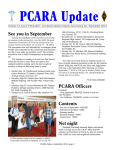
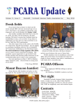
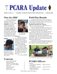
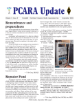
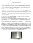
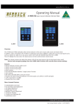
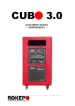
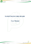
1
External keypad
pin 6 (GND) of the 8-pin round microphone plug when
a memory button is pressed.
If you have an Icom HF transceiver, then you
might find this project of interest — build yourself an
external keypad for around $34.00.
Key memories
Recent Icom HF transceivers — such as the
IC-7410A and IC-7000 — have a built-in electronic
memory keyer capable of storing up to four messages.
Some models also have a voice keyer to record short
voice announcements. The memory keyer can be
helpful for sending your callsign and standardized
contest exchanges — for example “CQ CQ de W2NYW
W2NYW” and “2A ENY”.
Calling up the stored memories is carried out using
“soft keys” positioned around the display. You need to
be in the correct part of the radio’s menu system before
these options appear. On the IC-7410, the sequence is
to select “CW” mode, press the “Menu” button to reach
Menu M1, press the F-4 “KEY” selection, then press the
F-2 “SEND” function-key. The four memory keys “M1”,
“M2”, “M3” and “M4” then appear on the display. This
Icom IC-7410 display showing “MENU” key and function
keys F-1 to F-5, ready to send from the four CW memories.
is not very convenient, especially if you want to use the
function keys for some other purpose such as the Band
Scope.
Plug-in shortcut
Fortunately, Icom allows connection of an external keypad to call up memory keyer contents at any
time. This keypad is normally plugged into the transceiver’s “MIC” connector, which will either be a screwon 8-pin round type or an 8-pin modular jack type.
Icom does not sell a suitable external keypad as an
accessory for their HF transceivers but they do provide
the circuit diagram for an external keypad in the
IC-7410 Instruction Manual — four different resistor
values are connected between pin 3 (UP/DOWN) and
Schematic from Icom IC-7410 User Manual for an External
Keypad that can access the four stored memories.
In recent years,
the “BetterRF Company” sold an “i-Mate”
external keypad for
Icom radios. The
i-Mate cost $85 and
was wired between the
existing microphone
and the radio’s MIC
connector. Unfortunately BetterRF does
not seems to be in
business any more.
The i-Mate external keypad was
manufactured by BetterRF.
Do it yourself
I decided to build my own external keypad, but
first I needed a suitable case for mounting the microphone connectors plus the four push-buttons for selecting memory contents. At a recent hamfest I had spotted
an MFJ-1251 “Universal Microphone Converter”. This
is a small
metal box
with front
panel connectors for both
an 8-pin
round microphone plug
and for an 8pin modular
plug. Separate
cables are provided for conMFJ-1251 Microphone Control
necting the
Center from MFJ Enterprises.
adapter to either
type of MIC
socket on the radio. The MFJ adapter allows one manufacturer’s microphone to be used with another manufacturer’s radio, which is often wired differently.
Headers and jumpers inside the case allow for a variety
of interconnections, so that (for example) an Alinco
microphone with a modular plug could be used with an
PCARA Update, September 2014, page 9
Icom radio having an 8-pin
round MIC socket. I thought the
MFJ-1251 would provide a good
basis for my external keypad.
At the ARRL Centennial
Convention in Hartford I purchased an MFJ-1251 adapter
from MFJ’s own booth. The price
was $29.95. Next day I purchased a packet of four momentary pushbutton switches from
Radio Shack — part number
275-1547, price $3.99. These
are the ‘normally open’ type.
Total so far — $33.94.
Radio Shack
momentary pushbutton switches.
The right connections
The first task was to evaluate the circuitry of MFJ’s
Universal Microphone Adapter. MFJ provides an
Instruction Manual containing the schematic plus connection diagrams for various combinations of microphone plug and radio manufacturer. My plan was to
use the Icom radio’s original HM-36 microphone with
the matching 8-pin round MIC socket on the Icom
transceiver. Unfortunately that straight-through combination is not included in the manual. (Not unexpected
though!)
Careful examination of the schematic showed that
MFJ selects four wires coming in from the microphone
for MIC-GND, MIC-AUDIO, MIC-PTT plus the 8 volt DC feed
to power any microphone circuitry, labeled THRU/PASS.
These four lines are then connected through appropriate jumpers
to the correct
pin-numbers
on the radio’s
“MIC” connector for:
RADIO-MICGND, RADIOMIC-AUDIO,
RADIO-PTT
and the
THRU/PASS
+8V DC line.
The black
ovals in the
diagram
alongside
MFJ-1251 jumper settings for an Alinco
modular-plug microphone connected to an show the
Icom radio with an 8-pin round MIC input. (default)
jumper settings for an Alinco modular microphone plug connected to an Icom 8-pin round MIC connector.
In order to arrange a “straight through” microphone connection for Icom-to-Icom, all you have to
do is combine
the left-hand
side of the
diagram for
your microphone connector with
the right
hand side of
the diagram
for your
radio’s MIC
connector.
See the
accompanying picture
Modified jumper settings for an Icom 8-pin
for an
round microphone connected to an Icom
radio with 8-pin round MIC input.
example for
“Icom 8-pin
Round Microphone Connector” combined with the
diagram for an “Icom 8 pin
Round Radio”.
(For readers who
might have an Icom radio
with an 8-pin modular
jack, I have provided a
smaller diagram for “Icom
Modular Microphone ConJumper settings for an Icom
nector” to an “Icom
Modular Radio”. I have not modular microphone plug
connected to an Icom radio
been able to test this
with modular MIC input.
arrangement myself.)
Step-by-step
In order to setup an MFJ-1251 adapter for a
straight
through connection, first
move the
jumpers from
their default
settings onto
new headers
as shown in
the appropriate diagram
— see the
photo alongside for an
example. You
MFJ-1251 with modified jumper settings
for an Icom 8-pin round microphone plug should then
carry out a
to an Icom 8-pin round MIC connector.
continuity
check with a multimeter on its ohms position to
confirm the connections from the 8-pin round micro-
PCARA Update, September 2014, page 10
phone connector on the front panel to the 8-pin round
microphone plug on the supplied cable. The important
pins to check are:
1. Microphone input
2. +8V DC output
5. PTT
6. GND (PTT ground)
7. GND (Microphone ground)
Next, you will need to drill four holes for the
momentary switches in the lid of the MFJ-1251 case.
For the Radio Shack switches, holes should be 17⁄64"
diameter and spaced 5⁄8" apart. Position the line of holes
equidistant from the front panel and rear panel to
avoid other components inside the metal case.
Mount the four Radio Shack switches in the holes,
then solder connecting wires and four resistors to the
switches as shown in Icom’s circuit for an external
keypad. The resistors I used — 1.5 kΩ (two off), 2.2 kΩ
and 4.7 kΩ, 1/8 watt — came out of my junk box.
up photo and accompanying diagram.
The Icom HM-36
microphone has two
buttons on top labeled “UP”
and “DOWN” for changing
frequency and memory
channel. I wanted these
Pinout and wiring of the
buttons to continue operaunused modular jack
tion when connected
position “J2” on the
through the MFJ-1251 adapter.
MFJ-1251 PCB
The UP and DOWN buttons
(component side).
work in a similar way to the
memory keyer buttons — the
DOWN button connects MIC pin 3 through a 470Ω
resistor to ground (pin 6) while the UP button directly
grounds MIC pin 3.
Icom 8-pin round microphone connections as seen from
the front panel. (From the IC-7410 Instruction Manual.)
The four momentary push-button switches and four resistors
are mounted in the lid of the MFJ-1251 metal case.
The components mounted in the top cover have to
be wired to Pin 3 and to Pin 6 of the 8-pin round
microphone connector output. The easiest way to do
this is to employ the empty position “J2” which is provided by MFJ on the circuit board for an additional
modular jack socket, but which is not used in this particular product. J2 is
located just
beneath the
front panel
8-pin round
connector.
Access for soldering to J2 is
available if
you gently
Close-up shows two wires from the case- push the
round conneclid switches soldered to the empty RJ45
modular jack position “J2”, at the pin 3 tor wires out
of the way —
and pin 6 locations. (Pin 1 is closest to
camera.)
see the close-
All you need to do to arrange for continued
UP/DOWN operation is to connect pin 3 of the 8-pin
round MIC connector on the MFJ-1251 front panel to
pin 3 of the empty modular jack position “J2”. A short
length of wire can be soldered between the appropriate
pins. J2 pin 3 should already have one of the wires
from the four push-buttons connected to it via 1.5 kΩ.
Final check
Before you plug the modified MFJ-1251 into your
expensive Icom radio, take a moment to verify all the
connections using an ohmmeter. There is a chance of
damaging the radio if the +8V supply has been wired
incorrectly. Pins 1, 2, 3, 5, 6 and 7 on the front panel’s
round connector should be connected straight through
to the same positions on the 8-pin round plug. Pins 6
and 7 (GND) will be connected to each other. In addition, you should check the resistance between pin 3
and pin 6 when each of these buttons is pressed — the
ohmmeter reading should be as follows:
M1 button
M2 button
M3 button
M4 button
Freq DOWN
Freq UP
PCARA Update, September 2014, page 11
1.5 kΩ
3.0 kΩ
5.2 kΩ
9.9 kΩ
470 Ω
0Ω
If all is well, plug your microphone into the modified MFJ adapter, then plug the adapter cable into your
Icom transceiver’s MIC socket. Before you check operation, you will need to enable “External Keypad” capability using
the radio’s
“Set Mode”
menu. For the
IC-7410, hold
down the
“Menu” button
to enter Set
Mode, then
choose menu
item 37,
“External
Keypad” and
change from
External keypad with the four memory
the default
buttons M1 - M4 suitably labeled.
“OFF” to
“KEYER
SEND” by rotating the VFO dial control. For enabling of
other Icom models, check your radio’s Instruction
Manual.
Make sure that the four keyer memory buttons are
working correctly, along with the normal functions of
the microphone — PTT, UP, DOWN and microphone
audio. If you are using a headset which requires
receiver audio from the radio, you will also need to
manually wire pin 8 (center pin on the round microphone connector) through to pin 8 on the output connector in a similar manner to the wiring for the
UP/DOWN buttons.
Choose your Icom
Bear in mind that different Icom HF transceivers
may need some modification to these instructions,
especially if the radio has a modular MIC jack. Check
the radio’s Instruction Manual for connections to the
microphone, for suggested circuitry of an external
keypad and for the “Set Mode” menu item that will
enable the external keypad. Icom models with a
memory keyer include the IC-746 Pro, IC-756 Pro 2
and 3, IC-7000, IC-7100, IC-7410, IC-7600, IC-7700
and IC-7800. The high-end IC-7700 and IC-7800 have
a separate 3.5mm stereo input jack for their external
keypad.
Best of luck with this little project! My own external keypad has already been put to good use for some
DX CW contacts.
- NM9J
Ready for some CW! The external keypad based on an
MFJ-1251 is shown in-line with the Icom HM-36 hand
microphone and cabled to the Icom IC-7410 8-pin round
MIC input at bottom left.
PCARA Update, September 2014, page 12