1
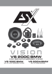
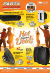
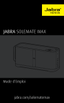
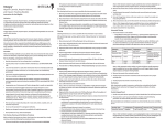
MVP
AMPLIFIERS
MVPA1
MVPA4
USER MANUAL
NVX MVP
THANK YOU FOR CHOOSING NVX
Thank you for choosing the NVX MVP Series of amplifiers for your car, boat, motorcycle, RV, ATV, or any other mobile application where big power and
great sound quality is needed for a small space application. The new MVP line of amplifiers are truly groundbreaking. The most compelling feature is
the small footprint, but don’t let the diminutive size fool you – these amplifiers utilize the latest in class D technology and cutting edge circuit design
to drive your gear. Previously when an ultra-small footprint amplifier was needed, you had to sacrifice both power and certainly sound quality. Thanks
to the innovation of the NVX design team you no longer have to make that sacrifice. The MVP line delivers power and quality normally reserved for
amplifiers that are 2-3 times their size. We’re not going to say the phrase “big things come in small packages” was inspired by our newest line of
amplifiers, but the MVP series certainly validates it. NVX has a proud tradition of building products that are as functional as they are innovative. With
the MVP line you can install these amplifiers in just about any application and achieve both the sound and power previously unheard of in a footprint
this small. The 4-channel MVPA4 is capable of delivering 100 watts per channel to drive your mids & highs and the MVPA1 monoblock is capable
of delivering 300 watts by one to drive your subwoofer, and both are contained in a case smaller than a video cassette tape. Now no matter the
application, you can rest assured that NVX has a product that’s right for you.
1
AMPLIFIERS
SPECIFICATIONS
MVPA1
MVPA4
RMS Power Output @ 14.4
200 Watts x 1 Ch @ 4 Ohm
300 Watts x 1 Ch @ 2 Ohm
50 Watts x 4 Ch @ 4 Ohm
100 Watts x 4 Ch @ 2 Ohm
Bridged 175 Watts x 2 Ch @ 4 Ohm
Frequency Response
Input Sensitivity
Signal-to Noise Ratio
Variable Lowpass Filter
Variable Highpass Filter
Bass Boost
Total Harmonic Distortion
Operating Voltage
Net Weight
10 Hz - 400 Hz
0.20 V - 5 V
105 dB
40 Hz - 400 Hz
–
0 / +6 / +12 dB
< 0.65 %
8 V - 16 V
2 lbs (0.90 kg)
10 Hz - 20 kHz
0.20 V - 5 V
101 dB
40 Hz - 400 Hz
40 Hz - 4 00 Hz
–
< 0.07 %
8 V - 16 V
2 lbs (0.90 kg)
1.56 in (39 mm)
5.44 in (138 mm)
4 in (102 mm)
1.56 in (39 mm)
5.44 in (138 mm)
4 in (102 mm)
RMS Power Output: 200 Watts x 1 Ch @ 4 Ohm 1% THD+N
Signal-to Noise Ratio: 82 dB (reference: 1 Watt @ 4 Ohm)
RMS Power Output: 50 Watts x 4 Ch @ 4 Ohm 1% THD+N
Signa-to Noise Ratio: 84 dB (reference: 1 Watt @ 4 Ohm)
Model Number
A Height
B Length
C Width
FEATURES
MVPA1
• Monoblock 1-Channel Amplifier
• Micro Class-D Circuitry
• LED Power/Protection Indicators
• 15A x 2 Mini-Blade Fuse
• Operating Voltage: 8V - 16V
• All Specs at Rated Power
MVPA4
• 4-Channel Bridgeable Amplifier
• Micro Class-D Circuitry
• LED Power/Protection Indicators
• 30A x 1 In-Line Mini-Blade Fuse
• Operating Voltage: 8V - 16V
• All Specs at Rated Power
A
B
Visit: nvx.com | Call: 213.444.1689 | 15303 Ventura Blvd. 9th Floor, Sherman Oaks, CA 91403
C
2
NVX MVP
SAFETY INFORMATION
● Please read and understand all instructions before attempting to use or install the amplifier. Damage caused by misuse is not covered under warranty.
● This unit is designed for use with 12VDC systems with negative ground only.
● Use only the supplied mounting hardware for a safe and secure installation.
● Adjust the volume to a safe and comfortable level when operating the motor vehicle.
● Never pour liquids on or near the amplifier, or place the product into a wet/moist environment. If liquid accidentally comes in contact with the
amplifier, disconnect all power and ground connections immediately.
● Clean the unit with a soft, dry cloth only. Never use chemicals or solvents such as alcohol or household cleaner.
INSTALLATION
STEP 1: MOUNTING THE AMPLIFIER
To ensure optimal performance and maximum longevity, the amplifier
should be mounted so there is suitable ventilation.
Install where there
is ventilation
to keep amp cool
Ideal locations include under the seat, in the trunk, or any other location
which provides adequate air space to keep amplifier cool. Due to the
potential temperature of the heat sink, it is recommended that you do
not mount the amp directly to fabric or vinyl material.
Once you’ve found a suitable location that provides ventilation and will
keep the amplifier dry , mount the amplifier using the included mounting
tabs. Make sure the amplifier is mounted securely.
Ideal Locations
STEP 2: MAKING POWER & GROUND CONNECTION
Be sure to use proper gauge wire for all power/ground connections. A
minimum 10 gauge wire is recommended. For the best results, using an
NVX amplifier installation kit is recommended.
GROUND: Prepare the chassis ground by clearing any paint, dirt and
grease from the metal surface. Connect a “ground” wire directly to the
chassis of the vehicle within 30 inches of the amplifier using a nonanodized screw and a star washer , and connect the other end to the
ground terminal. The ground should be kept as short as possible, and
should never exceed 30 inches.
3
Ground
AMPLIFIERS
INSTALLATION CONTINUED
POWER: Connect a wire directly to the vehicle’s positive battery
terminal, installing an appropriate fuse holder within 18 inches of the
battery. Route the wire to the amplifier’s location, connecting it to
the amplifier’s positive terminal (+12V). Be sure to use appropriate
grommets whenever routing the wires through the firewall or other sheet
metal. After routing and connecting this wire, you may install the fuse
into the fuse holder near the battery.
Source Unit’s Remote
Turn On
+12V
REMOTE: Connect the amplifier’s remote (Rem) terminal to either the
source unit’s remote turn-on lead, or an alternate switched 12V+ source
using a minimum of 18 gauge wire.
STEP 3: SIGNAL CONNECTIONS
The MVP amplifiers have been designed to accept both low-level “RCA”
inputs, as well as high-level speaker inputs through the included four/
eight-pin plug.
Fuse Holder
MVPA1 Signal Connection
Choose either RCA or 4-pin speaker plug
Battery Positive
Terminal
MVPA4 Signal Connection
Choose either RCA or 8-pin speaker plug
LOW-LEVEL RCA INPUTS: To use the low-level RCA inputs, connect
a high-quality RCA cable from the preamp outputs of the source unit to
the RCA inputs on the amplifier. For the clearest signal, we recommend
using an NVX shielded “noise-rejecting” twisted RCA cable.
HIGH-LEVEL SPEAKER INPUTS: To use the high-level speaker
inputs, connect each of the wires coming from the included connector
to the corresponding speaker output wires from the factory source unit.
Take care to match the polarity and channel of each wire. Once the
speaker wires have been spliced, plug the connector into the amplifier.
STEP 4: SUBWOOFER & SPEAKER CONNECTIONS
Once you’ve made the power, ground, remote, and signal connection
for the amplifier, you are ready to connect the speakers or subwoofer(s).
Simply connect the speaker wire to the terminals of the corresponding
speaker or subwoofer. For the best results, we recommend using NVX
speaker wire with a minimum size of 16 gauge.
4 Pin Plug
L
Rear
R
KEY
RL
RCA Inputs
MVPA1 Subwoofer Wiring Diagram
Subwoofer
8 Pin Plug
RR
Front
FL
FL
High-Level Inputs
MVPA4 Speaker Wiring Diagram
Front Speakers
Rear Speakers
R
L
Visit: nvx.com | Call: 213.444.1689 | 15303 Ventura Blvd. 9th Floor, Sherman Oaks, CA 91403
L
R
4
NVX MVP
TUNING THE AMPLIFIER
SETTING THE GAIN (LEVEL):
The gain control is designed to help match the input sensitivity of the
amplifier to the output voltage of the source unit. To set the gain, start
by turning the gain all the way down then turn up the source unit up to
3/4 volume. Slowly raise the gain until audible distortion is apparent
then back the gain down slightly until the distortion can no longer be
heard. For most users setting the gain up half way will achieve the
desired results.
*IMPORTANT NOTE
The gain dial is not a volume control and if set too high it will also
amplify any noise or distortion already present. This can potentially lead
to clipping.
MVPA1
MVPA4
Level
Level
Min Max
Min Max
Level
Min Max
SETTING THE BOOST SELECT:
The Bass Boost switch will increase the power output at 45Hz for more
pronounced bass. There are three setting for Bass Boost 0db, +6db and
+12db. Exercise caution when using this setting. We recommend 0db,
but if Boost is required start at +6db and listing for audible distortion
before increasing the Boost to +12db.
MVPA1 Only
Boost
SETTING THE INPUT SELECT
2-CHANNEL OPERATION
If your source unit has one set of pre-amp outputs (RCAs), set the
switch to 2-channel input. The signal will be summed to all channels.
This is ideal for source units with 1 pre-out or when bridging channels
1&2, 3&4.
4-CHANNEL OPERATION
If your source unit has two pairs of pre-amp outputs (RCAs) front and
rear/sub, set the switch to 4-channel input. This will send signal to all
4-channels and retains fader and balance control.
3-CHANNEL OPERATION
If your source unit has one pair of pre-amp outputs (RCAs) front or
rear. This is ideal when using one pair of speakers on channel 1&2 and
bridging 3&4 to a center channel or subwoofer.
5
MVPA4 Only
AMPLIFIERS
SETTING THE LOW-PASS FILTER
MVPA1
MVPA4
Freq
The low-pass filter (LPF) is designed to act as a “ceiling,” blocking out
any frequencies that are above the low pass setting crossover point.
This setting helps you filter out undesirable mid to high frequencies not
designed to be played on subwoofers. A good starting point is 80hz as
frequencies below 80hz are non directional. To set the LPF, simply turn
the knob to the desired crossover frequency.
Freq
Freq
SETTING THE PHASE CONTROL
Most car stereo installations feature the tweeters and midwoofers in the
front of the car, close to your ears. However, the subwoofer is usually
located in the trunk or rear of the car as far as 6-10 feet away . The
integrated phase adjustment knob can be used to help the sound from
all the speakers reach your ears at the same time.
MVPA1 Only
To set the phase control, start with the knob turned to zero. Gradually
adjust the setting until the bass sounds as if it is coming from the front
or center of the car, rather than from behind you. This may take several
minutes as you listen carefully to achieve the desired sound.
Phase
SETTING THE HIGH-PASS FILTER
The high-pass filter (HPF) is designed to act as a “floor,” blocking
out any frequencies that fall below the selected crossover point. This
setting helps you filter out undesirable bass frequencies for larger
speakers and woofers. A good starting point is 80hz as this frequency
range is above most speaker and tweeter resonant frequency levels,
and will blend well with your low pass setting of 80hz as well.
Freq
Freq
MVPA4 Only
To set the HPF, simply turn the knob to the desired crossover frequency.
Visit: nvx.com | Call: 213.444.1689 | 15303 Ventura Blvd. 9th Floor, Sherman Oaks, CA 91403
6
NVX MVP
TROUBLESHOOTING
TROUBLE
SOLUTION
• Verify remote turn-on wire has suffcient voltage
Power LED on amplier is not lit when
source is turned on
• Make sure power (+12V), ground (Gnd) and remote (Rem) connections are secure
• Check amplier fuse and in-line fuse
• Make sure power wire has suffcient voltage
Power LED is on, but no output from
speakers
Hearing engine noise through speakers
Amplier output distorted
• Check RCA/ High-Level Speaker connections to ensure amplier is receiving signal
• Check gain on amplier
• Check volume on source unit
• Turn the source off, then disconnect the RCA’s or speaker-level harness. If the
noise stops, check all wiring and equipment connected to the amplier and check
to make sure you have a solid ground connection. If the noise continues, contact
NVX tech support.
• Make sure source output is not distorted
• Check the input sensitivity to make sure gain is not set to high.
• Make sure amplier has proper ventilation
• Speakers are wired to the correct impedance for the application
Red LED protection indicator is lit
• Check to see if the speaker is short-circuited due to faulty connection or exposed wire.
• Make sure the speaker is crossover in the correct range.
• Make sure signal input is not shorted due to faulty connection or exposed wire.
7
AMPLIFIERS
WARRANTY
NVX warrants to the original retail purchaser that this product is to be free from defective materials and workmanship for a period of one (1) year from the date
of purchase, if it is properly used and maintained. If this product proves defective in either material or workmanship, NVX, at it’s discretion, will (a) repair the
product, or (b) replace the product, at no charge for parts or labor. If the product model is no longer available and cannot be repaired effectively or replaced
with an identical model, NVX at it’s sole option may replace the unit with a current model of equal or greater value. To obtain a repair or replacement under
the terms of this warranty, please return to dealer first, if possible, and the dealer will direct you accordingly for repairs or replacement. You will be required
to submit a copy of the original receipt. Return shipping for exchanges/repairs is the sole responsibility of the original retail purchaser.
LIMITATIONS:
• This limited warranty does not cover failure of the product resulting
• T his limited warranty is null and void for products with altered or
• T his limited warranty does not cover cosmetic damage, including paint
• T his limited warranty terminates if you sell or otherwise transfer this
improper installation, misuse, abuse, accident, neglect, mishandling,
or wear from ordinary use or environmental deterioration.
damage, or consequential damage to ordinary use or environmental
deterioration.
• T his limited warranty does not cover cosmetic damage, including paint
damage, or consequential damage to other components or premises
which may result for any reason from the failure of the product.
missing serial numbers and for products not purchased from an
authorized dealer.
product to another party.
• T his limited warranty is null and void for any speaker or subwoofer that
has been damaged due to over-powering causing burnt voice coils
and /or mechanical failures such as ripped spiders or surrounds.
• T his limited warranty is null and void for products not used in
accordance with NVX’s instructions.
THIS WARRANTY GIVES YOU SPECIFIC LEGAL RIGHTS, AND YOU MAY ALSO HAVE OTHER RIGHTS WHICH VARY FROM STATE TO STATE,
JURISDICTION TO JURISDICTION, OR COUNTRY TO COUNTRY. NVX’S RESPONSIBILITY FOR MALFUNCTIONS AND DEFECTS IN HARDWARE
IS LIMITED TO REPLACEMENT OR REPAIR AS SET FORTH IN THIS WARRANTY STATEMENT. ALL EXPRESS AND IMPLIED WARRANTIES FOR
THE PRODUCT, INCLUDING BUT NOT LIMITED TO ANY IMPLIED WARRANTIES OF MERCHANTABILITY AND FITNESS FOR A PARTICULAR PURPOSE,
ARE LIMITED IN TIME TO THE TERM OF THIS WARRANTY. SOME STATES, JURISDICTIONS, OR COUNTRIES DO NOT ALLOW THE EXCLUSION
OF CERTAIN IMPLIED WARRANTIES OR CONDITIONS, OR LIMITATIONS ON HOW LONG AN IMPLIED WARRANTY OR CONDITION LASTS, SO
THIS LIMITATION MAY NOT APPLY TO YOU. NVX DOES NOT ACCEPT LIABILITY FOR SPECIAL, INDIRECT, CONSEQUENTIAL, OR INCIDENTAL
DAMAGES, INCLUDING WITHOUT LIMITATION, ANY LIABILITY FOR THIRD PARTY CLAIMS AGAINST YOU FOR DAMAGES OR FOR PRODUCTS
NOT BEING AVAILABLE FOR USE. THE MAXIMUM LIABILITY FOR WHICH NVX MAY BE RESPONSIBLE WILL BE NO MORE THAN THE AMOUNT
YOU PAID FOR THE PRODUCT THAT IS THE SUBJECT OF THE CLAIM. SOME STATES, JURISDICTIONS, OR COUNTRIES DO NOT ALLOW THE
EXCLUSION OR LIMITATION OF SPECIAL, INDIRECT, INCIDENTAL, OR CONSEQUENTIAL DAMAGES, SO THE ABOVE LIMITATION OR EXCLUSION
MAY NOT APPLY TO YOU.
Warranty Outside the U.S.
The Warranty on this product shall comply with applicable law when sold to a consumer outside of the United States. To obtain any applicable warranty service,
please contact the dealer from which you purchased this product, or the distributor that supplied this product.
Visit: nvx.com | Call: 213.444.1689 | 15303 Ventura Blvd. 9th Floor, Sherman Oaks, CA 91403
8
NVX MVP
WHAT TO DO IF YOU NEED WARRANTY OR SERVICE
Defective products should be returned to the place of purchase. Your authorized NVX dealer
is trained to handle and expedite any warranty claim. Assistance in locating an authorized
dealer can be found at nvx.com or by contacting NVX directly.
Alternatively, if it becomes necessary for you to return defective product directly to NVX,
please refer to the following instructions for warranty service:
eceive your RA Number from NVX online at
• Rnvx.com/support
ackage all defective components in the original packaging (if
• Pavailable)
or in a package that will prevent shipping damage.
•
P
ackage the original packaging in an additional shipping
container to avoid shipping damages and to comply with most
shipping couriers such as UPS and FedEx.
your return at the price paid as NVX is not responsible for
• Insure
insurance losses or damages occurring in shipment to our facility.
mark RA Number on the outside shipping container.
• Clearly
only defective components as the return of functioning
• Return
items increases your return freight charges.
a copy of the original receipt with the purchase date
• Include
clearly visible, and a “proof-of-purchase” statement listing the
customer’s name, dealer’s name and invoice number, and
product purchased.
- Warranty expiration on items without proof-of-purchase will be
determined from type of sale and the manufacturing date code.
hip your package freight prepaid to the address below. Items
• Ssent
freight collect or COD will be refused.
NVX
Attn: Returns
10645 Freeport Dr.
Louisville, KY 40258-1873
- Non-defective returns or products not eligible for warranty
service will be returned freight collect.
Failure to follow the steps listed above may void your warranty. Any questions can be directed via email to
cs@nvx.com or via mail at the address listed above.
9
AMPLIFIERS
Authorized Dealer’s Name:
Purchase Date:
Model Number:
Serial Number:
Visit: nvx.com | Call: 213.444.1689 | 15303 Ventura Blvd. 9th Floor, Sherman Oaks, CA 91403
10
Visit: nvx.com | Call: 213.444.1689 | 15303 Ventura Blvd. 9th Floor, Sherman Oaks, CA 91403