1
User Manual
DIS-2 48/10
DIS-2 48/10 IC
DIS-2 48/10 FB
Metronix Meßgeräte und Elektronik GmbH
Telefon:
+49-(0)531-8668-0
Kocherstraße 3
Telefax:
+49-(0)531-8668-555
D-38120 Braunschweig
E-mail:
vertrieb@metronix.de
Germany
http://www.metronix.de
Seite 2
Copyrights
© 2006 Metronix Meßgeräte und Elektronik GmbH. All rights reserved.
The information and data in this document have been composed to the best of our knowledge.
However, deviations between the document and the product cannot be excluded entirely. For the
devices and the corresponding software in the version handed out to the customer, Metronix
guarantees the contractual use in accordance with the user documentation. In the case of serious
deviations from the user documentation, Metronix has the right and the obligation to repair, unless it
would involve an unreasonable effort. A possible liability does not include deficiencies caused by
deviations from the operating conditions intended for the device and described in the user
documentation.
Metronix does not guarantee that the products meet the buyer’s demands and purposes or that they
work together with other products selected by the buyer. Metronix does not assume any liability for
damages resulting from the combined use of its products with other products or resulting from
improper handling of machines or systems.
Metronix Meßgeräte und Elektronik GmbH reserves the right to modify, amend, or improve the
document or the product without prior notification.
This document may, neither entirely nor in part, be reproduced, translated into any other natural or
machine-readable language nor transferred to electronic, mechanical, optical or any other kind of data
media, without expressive authorisation by the author.
Trademarks
Any product names in this document may be registered trademarks. The sole purpose of any
trademarks in this document is the identification of the corresponding products.
ServoCommander is a registered trademark of Metronix Meßgeräte und Elektronik GmbH.
Microsoft and Windows are either registered trademarks or trademarks of Microsoft Corporation in the
United States and/or other countries.
User Manual DIS-2 „DIS-2 48/10 DIS-2 48/10 IC DIS-2 48/10 FB“
Version 1.1
Seite 3
Revision Log
Author:
Metronix Meßgeräte und Elektronik GmbH
Manual name:
User Manual "DIS-2 48/10, DIS-2 48/10 IC, DIS-2 48/10 FB"
File name:
UserManual_DIS-2_1p1.doc
Storage location of the file:
No.
Description
Revision index
Date of change
001
First authorized version
1.0
24.06.2005
002
Revision:
Extension to DIS-2 48/10 FB and to
firmware 3.0
1.1
15.05.2006
User Manual DIS-2 „DIS-2 48/10 DIS-2 48/10 IC DIS-2 48/10 FB“
Version 1.1
Seite 4
TABLE OF CONTENTS:
1
General ....................................................................................................13
1.1
1.2
Symbols used in this manual ............................................................................... 13
Features and area of application of the DIS-2 ..................................................... 13
1.2.1
1.2.2
1.2.3
1.3
DIS-2 ServoCommanderTM features .................................................................... 16
1.3.1
1.3.2
1.3.3
1.4
1.5
2
Basic information ................................................................................................13
Area of application and intended use .................................................................14
DIS-2 features ....................................................................................................14
Basic information ................................................................................................16
DIS-2 ServoCommanderTM features...................................................................16
Hardware and software requirements ................................................................16
Documentation.....................................................................................................17
Supply state and scope of supply ........................................................................ 17
Safety notes for electrical drives and controllers................................19
2.1
2.2
2.3
General notes ......................................................................................................19
Danger resulting from misuse.............................................................................. 20
Safety notes.........................................................................................................21
2.3.1
2.3.2
2.3.3
2.3.4
2.3.5
2.3.6
2.3.7
3
General safety notes ..........................................................................................21
Safety notes for assembly and maintenance .....................................................22
Protection against contact with electrical parts ..................................................23
Protection against electrical shock by means of protective extra-low voltage
(PELV) ................................................................................................................24
Protection against dangerous movements.........................................................24
Protection against contact with hot parts ...........................................................25
Protection during handling and assembly ..........................................................25
Preparation for commissioning.............................................................27
3.1
3.2
3.3
4
System overview..................................................................................................27
Connecting the DIS-2 to the control system ........................................................ 27
Installation and start of the DIS-2 ServoCommanderTM ....................................... 27
Initial parameterization of the controller ..............................................28
4.1
Commissioning ....................................................................................................28
4.1.1
4.1.2
4.2
4.3
Parameterization using the motor database ........................................................ 29
Basic parameterization of new motors................................................................. 30
4.3.1
4.3.2
4.3.3
4.3.4
4.3.5
4.3.6
4.4
Angle encoders...................................................................................................30
Motor data...........................................................................................................33
Power stage........................................................................................................35
Current controller................................................................................................36
DC bus monitoring..............................................................................................37
Motor temperature monitoring ............................................................................38
Configuring application parameters .....................................................................39
4.4.1
4.4.2
4.5
4.6
4.7
4.8
4.9
Parameter set in the delivery state.....................................................................28
Manual commissioning .......................................................................................28
General configuration .........................................................................................39
Configuring the display units ..............................................................................39
Defining input limits.............................................................................................. 41
Selecting safety parameters ................................................................................42
Configuring the controller enable logic ................................................................ 43
Configuring the limit switch polarity ..................................................................... 44
Setting the direction of rotation ............................................................................44
User Manual DIS-2 „DIS-2 48/10 DIS-2 48/10 IC DIS-2 48/10 FB“
Version 1.1
Seite 5
4.10
5
Making the system ready for operation, enabling the power stage ..................... 45
Current and speed control .....................................................................47
5.1
5.2
Function overview................................................................................................47
Speed-controlled mode........................................................................................ 49
5.2.1
5.2.2
5.3
5.4
Torque-controlled mode....................................................................................... 52
Setpoint assignment through setpoint selectors .................................................. 52
5.4.1
5.4.2
5.4.3
5.4.4
5.4.5
6
Optimizing the speed controller..........................................................................49
Optimization strategies .......................................................................................50
Speed-controlled mode ......................................................................................53
Torque-controlled mode .....................................................................................53
Setpoint assignment through RS232..................................................................54
Setpoint ramp .....................................................................................................54
Torque limitation .................................................................................................55
Positioning mode....................................................................................56
6.1
6.2
6.3
Function overview................................................................................................56
Activating the operating mode ............................................................................. 57
Configuring and optimizing the position controller ............................................... 58
6.3.1
6.4
6.5
6.6
6.7
6.8
Global positioning settings...................................................................................60
Parameterizing position sets................................................................................61
Approaching destinations ....................................................................................64
Setting of digital outputs ......................................................................................65
Homing ................................................................................................................65
6.8.1
6.8.2
7
Position controller optimization...........................................................................59
Homing methods ................................................................................................65
Parameterizing the homing run ..........................................................................69
Course program......................................................................................72
7.1
Creating a course program .................................................................................. 74
7.1.1
7.1.2
7.1.3
7.1.4
7.1.5
7.2
8
Course program options.....................................................................................75
End of program...................................................................................................76
Position branch...................................................................................................76
Branch (Line) ......................................................................................................78
Level test ............................................................................................................79
Debugging a course program ..............................................................................80
Function of the inputs and outputs.......................................................81
8.1
Digital inputs DIN0 to DIN9..................................................................................81
8.1.1
8.2
8.2.1
8.3
9
Configuring the digital outputs............................................................................86
Configuring the messages for the digital outputs ...............................................87
Incremental encoder emulation through DOUT1 and DOUT2 ............................. 89
Holding brake DOUT3 .........................................................................................90
8.5.1
8.6
8.7
Teaching positions..............................................................................................84
Digital outputs DOUT0 to DOUT3........................................................................86
8.3.1
8.3.2
8.4
8.5
Configuring the digital inputs ..............................................................................83
Extended function of the digital inputs (Tipp & Teach) ........................................ 83
Brake functions...................................................................................................90
Analog inputs AIN0 and AIN1 .............................................................................. 92
Analog output AMON........................................................................................... 93
Communication interfaces.....................................................................95
9.1
Control through the CAN bus...............................................................................95
User Manual DIS-2 „DIS-2 48/10 DIS-2 48/10 IC DIS-2 48/10 FB“
Version 1.1
Seite 6
9.1.1
9.1.2
9.1.3
9.2
Control through the serial interface...................................................................... 97
9.2.1
9.2.2
9.2.3
9.2.4
9.2.5
9.3
10
Function overview...............................................................................................95
Processing of CAN messages............................................................................96
Configuring the CANopen communication parameters......................................96
Function overview...............................................................................................97
Serial communication through DIS-2 ServoCommanderTM ................................98
Configuring the RS232 communication parameters ..........................................98
Transfer window .................................................................................................99
Communication window for RS232 transmission...............................................99
Control through the technology interface........................................................... 100
Error messages/Error table .................................................................101
10.1
Error monitoring in the DIS-2 .............................................................................101
10.1.1
10.1.2
10.1.3
10.1.4
10.1.5
10.1.6
10.1.7
10.1.8
10.2
10.3
10.4
11
Overcurrent and short-circuit monitoring......................................................... 101
DC bus voltage monitoring .............................................................................. 101
Logic supply monitoring................................................................................... 102
Heat sink temperature monitoring ................................................................... 102
Motor monitoring.............................................................................................. 102
Motion sequence monitoring ........................................................................... 103
Additional internal monitoring functions........................................................... 103
Operating hour meter ...................................................................................... 103
Error overview....................................................................................................103
Error display in DIS-2 ServoCommanderTM ....................................................... 108
Error management............................................................................................. 109
Appendix ...............................................................................................110
11.1
DIS-2 ServoCommanderTM operating instructions ............................................. 110
11.1.1
11.1.2
11.1.3
11.1.4
11.1.5
11.1.6
11.1.7
11.1.8
11.2
11.3
11.4
11.5
Setting up the serial communication..................................................................115
Info window........................................................................................................117
Fast access via the tool bar ...............................................................................118
Using the oscilloscope function .........................................................................119
11.5.1
11.5.2
11.6
11.7
Basic units ....................................................................................................... 134
Bit configuration for command word / status word / error word....................... 135
Extended options in the "Display units" menu ................................................... 139
11.8.1
11.8.2
11.8.3
11.9
Oscilloscope settings....................................................................................... 119
Oscilloscope window ....................................................................................... 121
Serial communication protocol........................................................................... 124
List of communication objects............................................................................126
11.7.1
11.7.2
11.8
Standard buttons ............................................................................................. 110
Numerical input fields ...................................................................................... 110
Control elements ............................................................................................. 111
Display of setpoints and actual values ............................................................ 111
Standard window ............................................................................................. 112
Directories ....................................................................................................... 113
Communication via communication objects .................................................... 113
Quitting the program........................................................................................ 114
Configuration of user-defined display units ..................................................... 139
Decimal places ................................................................................................ 140
Direct input of distance, speed and acceleration units.................................... 140
Course program: Examples ............................................................................... 141
11.9.1
11.9.2
11.9.3
Example 1: Linear linking of positions ............................................................. 141
Example 2: Linear linking of positions and setting of a digital output.............. 142
Example 3: Setting and inquiring digital inputs and outputs; infinite loops ..... 143
User Manual DIS-2 „DIS-2 48/10 DIS-2 48/10 IC DIS-2 48/10 FB“
Version 1.1
Seite 7
11.10 Timing diagrams ................................................................................................143
11.10.1
11.10.2
11.10.3
11.10.4
11.10.5
Switch-on sequence ........................................................................................ 144
Positioning / Destination reached.................................................................... 145
Speed signal.................................................................................................... 145
Quit error.......................................................................................................... 146
Limit switch ...................................................................................................... 146
11.11 Parameter set management .............................................................................. 147
11.11.1 General ............................................................................................................ 147
11.11.2 Loading and saving parameter sets ................................................................ 148
11.11.3 Printing parameter sets ................................................................................... 149
11.12 Offline parameterization..................................................................................... 151
11.13. Loading firmware into the DIS-2 / firmware update ........................................... 152
11.13.1 Loading the firmware ....................................................................................... 153
11.14. Technical data ...................................................................................................155
11.14.1
11.14.2
11.14.3
11.14.4
11.14.5
11.14.6
11.14.7
11.14.8
11.14.9
11.14.10
11.14.11
11.14.12
11.14.13
11.14.14
11.14.15
Ambient conditions and qualification ............................................................... 155
Dimensions and weight ................................................................................... 155
Performance data ............................................................................................ 155
Motor temperature monitoring ......................................................................... 156
Motor connection data [X301 – X303] ............................................................. 156
Resolver [X2] ................................................................................................... 156
Analog Hall encoder evaluation [X2] ............................................................... 157
Hiperface encoder evaluation [X2] .................................................................. 157
Incremental encoder evaluation [X2] – only DIS-2 48/10 FB .......................... 157
Six-Step Hall sensor and block commutation [X2] .......................................... 158
RS232 [X1] ...................................................................................................... 158
CAN-Bus [X1] .................................................................................................. 158
Analog inputs and outputs [X1] ....................................................................... 158
Digital inputs and outputs [X1]......................................................................... 159
Incremental encoder output [X1] ..................................................................... 159
11.15. Mechanical installation.......................................................................................160
11.15.1
11.15.2
11.15.3
11.15.4
Important notes................................................................................................ 160
Position and connection of the pin-and-socket connectors............................. 161
Housing dimensions ........................................................................................ 162
Installation........................................................................................................ 163
11.16. Connectors at the DIS-2 48/10 .......................................................................... 164
11.16.1
11.16.2
11.16.3
11.16.4
11.16.5
Connection: Power supply and I/O [X1] .......................................................... 164
Connection: Angle encoder [X2]...................................................................... 165
Connection: Motor [X301 – X303] ................................................................... 166
Connection: Holding brake [X3]....................................................................... 166
Connection: Extension port [X8]...................................................................... 167
11.17. Connectors at the DIS-2 48/10 IC...................................................................... 168
11.17.1 Connection: Power supply and I/O [X1] .......................................................... 168
11.17.2 Connection: Motor, encoder, brake, extensions.............................................. 169
11.18. Connectors at the DIS-2 48/10 FB..................................................................... 169
11.18.1
11.18.2
11.18.3
11.18.4
11.18.5
11.18.6
Connection: Power supply and I/O [X1] .......................................................... 169
Connection: Motor, encoder, brake, extensions.............................................. 170
Brake resistance connection [X304 – X305] ................................................... 171
Connection: CAN bus [X401] and [X402] ........................................................ 172
Connection: Serial parameterization interface [X5]......................................... 173
Connection: Extension port [X8]...................................................................... 174
11.19 Electrical installation of the DIS-2 48/10 ............................................................ 176
11.19.1 Connection to Power Supply and control in system........................................ 176
11.19.2 EMERGENCY OFF / EMERGENCY STOP – terminology and standards ..... 178
11.19.3 EMERGENCY OFF / EMERGENCY STOP wiring examples ......................... 180
User Manual DIS-2 „DIS-2 48/10 DIS-2 48/10 IC DIS-2 48/10 FB“
Version 1.1
Seite 8
11.20 Notes concerning safe and EMC-compliant installation .................................... 183
11.20.1
11.20.2
11.20.3
11.20.4
11.20.5
Definitions and terminology ............................................................................. 183
General information concerning EMC ............................................................. 183
EMC ranges: First and second environment................................................... 183
Connection between the DIS-2 and the motor ................................................ 184
Connection between the DIS-2 and the power supply unit ............................. 184
User Manual DIS-2 „DIS-2 48/10 DIS-2 48/10 IC DIS-2 48/10 FB“
Version 1.1
Seite 9
List of Figures:
Figure 1: Current controller step response.............................................................................................37
Figure 2: Speed controller ......................................................................................................................48
Figure 3: Speed controller too soft .........................................................................................................51
Figure 4: Speed controller too hard........................................................................................................51
Figure 5: Speed controller set correctly .................................................................................................51
Figure 6: Positioning control block diagram ...........................................................................................56
Figure 7: Speed controller optimization..................................................................................................59
Figure 8: Time-optimal and jerk-limited positioning................................................................................63
Figure 9: Homing run to the negative limit switch with index pulse evaluation ......................................66
Figure 10: Homing run to the positive limit switch with index pulse evaluation .....................................66
Figure 11: Homing to the negative limit switch.......................................................................................67
Figure 12: Homing to the positive limit switch ........................................................................................67
Figure 13: Homing run referred only to the index pulse.........................................................................67
Figure 14: Homing run to the negative stop with index pulse evaluation...............................................68
Figure 15: Homing run to the positive stop with index pulse evaluation ................................................68
Figure 16: Homing to the negative stop .................................................................................................68
Figure 17: Homing to the positive stop...................................................................................................69
Figure 18: Course program - Position branch ........................................................................................77
Figure 19: Position branch time diagram ...............................................................................................77
Figure 20: Course program - Branch (Line) ...........................................................................................78
Figure 21: Branch (Line) time diagram...................................................................................................79
Figure 22: Level test course program ....................................................................................................79
Figure 23: Level test time diagram .........................................................................................................80
Figure 24: Teaching process of a target position ...................................................................................85
Figure 25: Coupled incremental encoder emulation ..............................................................................89
Figure 26: Holding brake time response ................................................................................................91
Figure 27: Safe zero ...............................................................................................................................93
Figure 28: Online parameterization ..................................................................................................... 147
Figure 29: Offline parameterization ..................................................................................................... 151
Figure 30: Arrangement of DIS-2 pin-and-socket connectors - top view of electronics module......... 161
Figure 31: Housing dimensions........................................................................................................... 162
Figure 32: DIS-2 application example - Synchronous servo motor in the power range of 500 W with a
DIS-2 servo positioning controller and a gearbox for a steering application..................... 163
User Manual DIS-2 „DIS-2 48/10 DIS-2 48/10 IC DIS-2 48/10 FB“
Version 1.1
Seite 10
Figure 33: Numbered pins of X1 DIS-2 48/10 ..................................................................................... 164
Figure 34: Angle encoder connector ................................................................................................... 165
Figure 35: Motor cable connection ...................................................................................................... 166
Figure 36: Holding brake connection .................................................................................................. 166
Figure 37: Technology module connection ......................................................................................... 167
Figure 38: Numbered pins of X1 DIS-2 48/10 IC ................................................................................ 168
Figure 39: Numbered pins of [X1] DIS-2 48/10 FB ............................................................................. 169
Figure 40: Brake resistance connection.............................................................................................. 171
Figure 41: Position and numbered pins [X401], [X402] and [X5] at DIS-2 48/10 FB .......................... 172
Figure 42: Position and connection technology module ..................................................................... 174
Figure 43: Connection to power supply, control and motor ................................................................ 176
Figure 44: Wiring example for the power supply and EMERGENCY OFF / EMERGENCY STOP.... 181
Figure 45: Connection of the DIS-2 to the power supply unit, shield connection on the chassis ....... 185
Figure 46: Connection of the DIS-2 to the power supply unit, shield connection via cable ................ 185
User Manual DIS-2 „DIS-2 48/10 DIS-2 48/10 IC DIS-2 48/10 FB“
Version 1.1
Seite 11
List of Tables:
Table 1: Scope of supply........................................................................................................................17
Table 2: Additional parameterization program .......................................................................................17
Table 3: DIS-2 48/10 accessories ..........................................................................................................18
Table 4: DIS-2 48/10 IC and DIS-2 48/10 FB accessories ....................................................................18
Table 5: Angle encoder parameters .......................................................................................................32
Table 6: Display mode............................................................................................................................40
Table 7: Error elimination: Speed control...............................................................................................46
Table 8: Course program: Assignment of the digital inputs ...................................................................73
Table 9: Course program: Configuration of the digital inputs (new I/O configuration)...........................73
Table 10: Available position sets if the course program is active and the Course/Posi input = 0 .........74
Table 11: DIS-2 48/10 digital inputs - possible combinations ................................................................81
Table 12:DIS-2 48/10 IC digital inputs - possible combinations.............................................................81
Table 13: DIS-2 48/10 FB digital inputs - possible combinations...........................................................81
Table 14: Digital inputs - assignment .....................................................................................................82
Table 15: Tipp & Teach: Configuration of the digital inputs ...................................................................84
Table 16: Error overview ..................................................................................................................... 104
Table 17: Control elements ................................................................................................................. 111
Table 18: Directories ........................................................................................................................... 113
Table 19: Recovering problems with serial communication................................................................ 116
Table 20: Command syntax of communication objects ...................................................................... 124
Table 21: Meaning of letters in the command syntax.......................................................................... 124
Table 22: RS232 command syntax ..................................................................................................... 125
Table 23: Meaning of letters in the command syntax.......................................................................... 125
Table 24: List of all communication objects ........................................................................................ 126
Table 25: List of basic units................................................................................................................. 134
Table 26: Online/Offline activation ...................................................................................................... 151
Table 27: Pin assignment of connector [X1] ....................................................................................... 164
Table 28: Pin assignment of connector [X2] ....................................................................................... 165
Table 29: Pin assignment of connector [X301 – X303]....................................................................... 166
Table 30: Pin assignment of connector [X3] ....................................................................................... 166
Table 31: Pin assignment of connector [X8] ....................................................................................... 167
Table 32: Pin assignment of connector [X1] ....................................................................................... 168
Table 33: Pin assignment of connector [X1] ....................................................................................... 170
User Manual DIS-2 „DIS-2 48/10 DIS-2 48/10 IC DIS-2 48/10 FB“
Version 1.1
Seite 12
Table 34: Pin assignment of connector [X304], [X305] ....................................................................... 171
Table 35: Pin assignment of connector [X401] and [X402]................................................................. 172
Table 36: Pin assignment of connector [X5] ....................................................................................... 173
Table 37: Pin assignment to set up an RS232 adapter cable for connection to a PC/notebook ........ 173
Table 38 (A): Pin assignment of connector [X8].................................................................................. 174
Table 39: Description of the requirements to be met for the categories in accordance with EN 954-1178
Table 40: EMERGENCY OFF and EMERGENCY STOP according to EN 60204-1.......................... 179
Table 41: Stop categories ................................................................................................................... 179
User Manual DIS-2 „DIS-2 48/10 DIS-2 48/10 IC DIS-2 48/10 FB“
Version 1.1
Page 13
1 General
1.1 Symbols used in this manual
Information
Important information and notes.
Caution!
Non-observance may result in severe property damage.
DANGER !
Non-observance may result in property damage and personal injuries.
Caution! Dangerous voltage.
The safety note indicates the possibility of a highly dangerous voltage.
1.2
Features and area of application of the DIS-2
1.2.1
Basic information
DIS-2 servo positioning controllers (Decentralized Intelligent Servo 2nd Generation) are intelligent
servo converters with extensive parameterization options. Due to this flexibility, they can be adapted
to numerous areas of application.
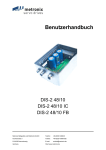
Type key:
DIS-2 48/10-IC
Configuration / connector
RMS output current in ampere
DC bus voltage
2nd generation
Type denomination
User Manual DIS-2 „DIS-2 48/10 DIS-2 48/10 IC DIS-2 48/10 FB“
Version 1.1
Page 14
1.2.2
Area of application and intended use
The DIS-2 servo positioning controller was designed for the decentralized control of three-phase
magneto-electric synchronous machines. Thanks to numerous options for feedback and to various
different control methods, such as "block commutation" and "sine commutation", the controller can be
adapted optimally to the motor characteristics.
Normally, it is mounted directly on the motor. However, it is also possible to detach the DIS-2 from the
motor and to connect it to the motor using a short, shielded cable. Further information concerning the
installation can be found in the appendix in chapter 11.15 Mechanical installation.
The DIS-2 servo positioning controller is supplied with power through a power supply unit or a battery
with 24 V DC or 48 V DC protective low voltage. At the motor connection, it supplies the synchronous
machine with a pulse-width-modulated, symmetrical, 3-phase rotating field with variable frequency,
current and voltage.
The DIS-2 was designed for a continuous torque, speed and position control in typical industrial
applications such as:
•
Positioning and feeding drives in machines
•
Palletizing and packaging machines
•
Wood-processing machines
•
Reeling drives, wire drawing drives etc.
•
Drives in tightening and press-fitting applications
•
Conveying applications
Prior to using the DIS-2 controller in special areas of application with particularly high normative
requirements, e.g. medical technology or avionics, requiring particularly high levels of device safety,
the user has to check whether the DIS-2 fulfils the corresponding standards. In case of doubt, please
contact your local distributor.
The DIS-2 may only be used if the operating conditions described and the technical data of the
controller stated in the appendix in chapter 11.14 Technical data are complied with. In addition, all
relevant regulations concerning installation, start-up, dismounting and maintenance have to be
complied with.
1.2.3
DIS-2 features
The DIS-2 has the following features:
Compact design. The housing (closed on five sides) can be mounted on the motor either
directly or using an adapter plate.
Highly precise control thanks to a high-quality sensor system.
Full integration of all components for the controller and power section, including an RS232
interface for PC communication and a CANopen interface for integration in automation
systems.
Integrated universal rotary encoder evaluation for the following encoder types:
Resolvers
User Manual DIS-2 „DIS-2 48/10 DIS-2 48/10 IC DIS-2 48/10 FB“
Version 1.1
Page 15
Analog Hall sensors with SIN/COS signals (upon request)
High-resolution Stegmann incremental encoders, absolute encoders with HIPERFACE
Six-step Hall encoders
Incremental encoders with commutation signals
Integrated driver stage for 24 V holding brakes
Compliance with current CE and EN standards without any additional external filter measures
EMC-optimized metal housing for direct mounting on the motor. The device has an IP54
degree of protection. Depending on the mounting methods and the seals used, a degree of
protection up to IP67 can be reached.
Integration of all filters in the unit required for compliance with the EMC regulations (industrial
environment), e.g. filters for the 24 V supply and the inputs and outputs.
Can be used as a torque controller, speed controller or position controller.
Integrated positioning control with extensive functionality in accordance with "CAN in
Automation (CiA) DSP402" and numerous additional application-specific functions.
Jerk-free or time-optimal positioning, relative or absolute with regard to a reference point.
Point-to-point positioning with and without spot tracing.
Speed- and angle-synchronous operation with an electronic gearbox via field bus.
Numerous homing methods.
Changeable clock frequency for the output stage.
Integrated course program to create simple positioning sequences with or without
dependence on digital inputs.
Programmable digital outputs.
High-resolution 12-bit analog input.
User-friendly parameterization using the DIS-2 ServoCommander
TM
PC program.
Automatic motor identification.
Easy connection to a superordinated control system, e.g. to a PLC on the I/O level or via a
field bus.
Technology slot for extensions, e.g. field bus connections (only DIS-2 48/10 FB)
I²t monitoring system to limit the average power loss in the power stage and in the motor.
Integrated brake chopper (only DIS-2 48/10 FB)
Separate RS232 and field bus connection (only DIS-2 48/10 FB)
User Manual DIS-2 „DIS-2 48/10 DIS-2 48/10 IC DIS-2 48/10 FB“
Version 1.1
Page 16
1.3
DIS-2 ServoCommanderTM features
1.3.1
Basic information
The parameterization program ensures the comfortable parameterization of the DIS-2 servo
positioning controller. You adapt the DIS-2 servo positioning controller optimally to your application
using the parameterization software.
The firmware of the DIS-2 servo positioning controller must match the parameterization software. This
means that following an extension of functionality in a new firmware version, you also require the
corresponding new version of the parameterization program.
You cannot parameterize any other Metronix devices using this parameterization
software.
1.3.2
DIS-2 ServoCommanderTM features
The parameterization program has the following features:
Parameterization of the DIS-2 servo positioning controller.
Configuration of all parameters using the PC.
Display of operating quantities.
Loading of new firmware versions.
Loading and saving of parameter sets.
Printing of parameter sets.
Offline parameterization.
Oscilloscope function.
Languages: German, English, French.
Windows-conform operation.
Course program.
1.3.3
Hardware and software requirements
Requirements to be met for installing the parameterization program:
IBM-compatible PC-AT, Pentium II processor or higher with at least 32 MB main memory and
at least 10 MB free hard-disk memory.
Operating system Windows® 95, Windows® 98, Windows NT®, Windows 2000, Windows XP®
CD-ROM drive.
Free serial interface.
User Manual DIS-2 „DIS-2 48/10 DIS-2 48/10 IC DIS-2 48/10 FB“
Version 1.1
Page 17
1.4
Documentation
This software manual is intended to ensure safe working with the DIS-2 ServoCommanderTM
parameterization program for the DIS-2 servo positioning controller.
Further information can be found in the following manuals of the DIS-2 product range:
CANopen manual "CanOpen_Manual_DIS-2": Description of the implemented CANopen
protocol in accordance with DSP402.
Mounting instructions "Mounting instructions_DIS-2": Instruction manual concerning the
installation of the DIS-2 servo positioning controller.
The servo positioning controller has a FLASH program memory allowing the operating software of the
controller to be updated even after it has be delivered and installed in a machine. The manufacturer is
continuously revising and extending the operating software of the controller to meet a wide range of
customer requirements.
The information stated in this manual refers to the following versions of the controller
operating software and of the parameterization program:
DIS-2 servo positioning controller firmware:
Version 3.0
Parameterization software:
1.5
Version 2.1
Supply state and scope of supply
The supply comprises:
Table 1: Scope of supply
1x
DIS-2 servo positioning controller
Supply state:
Default parameter set for operating the resolver motor.
Table 2: Additional parameterization program
1x
DIS-2 ServoCommander
Windows® parameterization program
German/English/French
Metronix part number: 9019-0900-00
Mating connectors for power, control or rotary encoder connections are not part of the standard scope
of supply. They can be ordered as accessories:
User Manual DIS-2 „DIS-2 48/10 DIS-2 48/10 IC DIS-2 48/10 FB“
Version 1.1
Page 18
Table 3: DIS-2 48/10 accessories
1x
Connector set: AMP pin-and-socket connector
Content:
1x
1x
16-pin AMP mating connector, incl.
crimp contacts
1x
16-pin mating connector for angle
encoder, incl. crimp contacts
1x
2-pin mating connector for holding
brake, incl. crimp contacts
DIS-2 control panel with AMP pin-and-socket
connector
Metronix part number: 9019-0200-00
Metronix part number: 9019-0300-00
Table 4: DIS-2 48/10 IC and DIS-2 48/10 FB accessories
1x
Connector set: Phoenix pin-and-socket connector
(been suitable for DIS-2 IC and DIS-2 FB)
Content:
1x
18-pin Phoenix mating connector
comprising:
VARICON mating connector,
sleeve frame and sleeve housing
1x
16-pin mating connector for angle
encoder, incl. crimp contacts
1x
2-pin mating connector for holding
brake, incl. crimp contacts
Metronix part number: 9019-0210-00
1x
DIS-2 IC control panel with Phoenix pin-and-socket Metronix part number: 9019-0310-00
connector
1x
DIS-2 FB control panel with Phoenix pin-andsocket connector
Metronix-part number: 9019-0320-00
1x
RS232 connecting cable for DIS-2 48/10 FB
Metronix-part number: 9019-0221-00
Assembled connecting cable for the controller
parameter configuration, length approx. 150 cm,
M8 circular connector for connection to the
controller, DSUB9 connector for connection to the
COM port of the PC.
1x
Braking resistor for DIS-2 48/10 FB
Metronix-part number: 9519-0001-00
Plate resistor, Metallux PLR 250, 5 Ω ± 10%, 100
W, dimensions 55 mm x 43 mm, height: 1.5 mm,
height in the area of the connecting cable 4 mm,
with strands l = 100 mm
User Manual DIS-2 „DIS-2 48/10 DIS-2 48/10 IC DIS-2 48/10 FB“
Version 1.1
Page 19
2 Safety notes for electrical drives and
controllers
2.1 General notes
In the case of damage resulting from non-compliance of the safety notes in this manual
Metronix Meßgeräte und Elektronik GmbH will assume any liability.
If the documentation in the language at hand is not understood accurately, please contact and inform
your supplier.
Sound and safe operation of the servo drive controller requires proper and professional transportation,
storage, assembly and installation as well as proper operation and maintenance. Only trained and
qualified personnel may handle electrical devices:
In the sense of this product manual or the safety notes on the product itself are persons who are
sufficiently familiar with the setup, assembly, commissioning and operation of the product as well as
all warnings and precautions as per the instructions in this manual and who are sufficiently qualified in
their field of expertise:
Education and instruction or authorisation to switch devices/systems on and off and to ground
them as per the standards of safety engineering and to efficiently label them as per the job
demands.
Education and instruction as per the standards of safety engineering regarding the
maintenance and use of adequate safety equipment.
First aid training.
The following notes must be read prior to the initial operation of the system to prevent personal
injuries and/or property damages:
These safety notes must be complied with at all times.
Do not try to install or commission the servo drive controller before carefully reading all
safety notes for electrical drives and controllers contained in this document. These
safety instructions and all other user notes must be read prior to any work with the servo
drive controller.
In case you do not have any user notes for the servo drive controller, please contact
your sales representative. Immediately demand these documents to be sent to the
User Manual DIS-2 „DIS-2 48/10 DIS-2 48/10 IC DIS-2 48/10 FB“
Version 1.1
Page 20
person responsible for the safe operation of the servo drive controller.
If you sell, rent and/or otherwise make this device available to others, these safety notes
must also be included.
The user must not open the servo drive controller for safety and warranty reasons.
Professional control process design is a prerequisite for sound functioning of the servo
drive controller!
DANGER!
Inappropriate handling of the servo drive controller and non-compliance of the
warnings as well as inappropriate intervention in the safety features may result in
property damage, personal injuries, electric shock or in extreme cases even death.
2.2 Danger resulting from misuse
DANGER!
High electrical voltages and high load currents!
Danger to life or serious personal injury from electrical shock!
DANGER!
High electrical voltage caused by wrong connections!
Danger to life or serious personal injury from electrical shock!
DANGER!
Surfaces of device housing may be hot!
Risk of injury! Risk of burning!
DANGER!
Dangerous movements!
Danger to life, serious personal injury or property damage due to unintentional
movements of the motors!
User Manual DIS-2 „DIS-2 48/10 DIS-2 48/10 IC DIS-2 48/10 FB“
Version 1.1
Page 21
2.3 Safety notes
2.3.1 General safety notes
The servo drive controller corresponds to IP54 class of protection as well as pollution
level 1. Make sure that the environment corresponds to this class of protection and
pollution level.
Only use replacements parts and accessories approved by the manufacturer.
The devices must be connected to the mains supply as per EN regulations, so that they
can be cut off the mains supply by means of corresponding separation devices (e.g.
main switch, contactor, power switch).
Gold contacts or contacts with a high contact pressure should be used to switch the
control contacts.
Preventive interference rejection measures should be taken for control panels, such as
connecting contactors and relays using RC elements or diodes.
The safety rules and regulations of the country in which the device will be operated must
be complied with.
The environment conditions defined in the product documentation must be kept. Safetycritical applications are not allowed, unless specifically approved by the manufacturer.
For notes on installation corresponding to EMC, please refer to chapter 11.20 Notes
concerning safe and EMC-compliant installation
The compliance with the limits required by national regulations is the responsibility of the
manufacturer of the machine or system.
The technical data and the connection and installation conditions for the servo drive
controller are to be found in this product manual and must be met.
DANGER!
The general setup and safety regulations for work on power installations (e.g. DIN, VDE,
EN, IEC or other national and international regulations) must be complied with.
Non-compliance may result in death, personal injury or serious property damages.
User Manual DIS-2 „DIS-2 48/10 DIS-2 48/10 IC DIS-2 48/10 FB“
Version 1.1
Page 22
Without claiming completeness, the following regulations and others apply:
VDE 0100
Regulations for the installation of high voltage (up to 1000 V) devices
EN 60204
Electrical equipment of machines
EN 50178
Electronic equipment for use in power installations
2.3.2 Safety notes for assembly and maintenance
The appropriate DIN, VDE, EN and IEC regulations as well as all national and local safety regulations
and rules for the prevention of accidents apply for the assembly and maintenance of the system. The
plant engineer or the operator is responsible for compliance with these regulations:
The servo drive controller must only be operated, maintained and/or repaired by
personnel trained and qualified for working on or with electrical devices.
Prevention of accidents, injuries and/or damages:
Additionally secure vertical axes against falling down or lowering after the motor has
been switched off, e.g. by means of:
Mechanical locking of the vertical axle,
External braking, catching or clamping devices or
Sufficient balancing of the axle.
The motor holding brake supplied by default or an external motor holding brake driven
by the drive controller alone is not suitable for personal protection!
Render the electrical equipment voltage-free using the main switch and protect it from
being switched on again until the DC bus circuit is discharged, in the case of:
Maintenance and repair work
Cleaning
long machine shutdowns
Prior to carrying out maintenance work make sure that the power supply has been
turned off, locked and the DC bus circuit is discharged.
Be careful during the assembly. During the assembly and also later during operation of
the drive, make sure to prevent drill chips, metal dust or assembly parts (screws, nuts,
cable sections) from falling into the device.
Also make sure that the external power supply of the controller (24V) is switched off.
User Manual DIS-2 „DIS-2 48/10 DIS-2 48/10 IC DIS-2 48/10 FB“
Version 1.1
Page 23
The DC bus circuit or the mains supply must always be switched off prior to switching off
the 24V controller supply.
Carry out work in the machine area only, if AC and/or DC supplies are switched off.
Switched off output stages or controller enablings are no suitable means of locking. In
the case of a malfunction the drive may accidentally be put into action.
Initial operation must be carried out with idle motors, to prevent mechanical damages
e.g. due to the wrong direction of rotation.
Electronic devices are never fail-safe. It is the user’s responsibility, in the case an
electrical device fails, to make sure the system is transferred into a secure state.
The servo drive controller and in particular the brake resistor, externally or internally, can
assume high temperatures, which may cause serious burns.
2.3.3 Protection against contact with electrical parts
This section only concerns devices and drive components carrying voltages exceeding 50 V. Contact
with parts carrying voltages of more than 50 V can be dangerous for people and may cause electrical
shock. During operation of electrical devices some parts of these devices will inevitably carry
dangerous voltages.
DANGER!
High electrical voltage!
Danger to life, danger due to electrical shock or serious personal injury!
The appropriate DIN, VDE, EN and IEC regulations as well as all national and local safety regulations
and rules for the prevention of accidents apply for the assembly and maintenance of the system. The
plant engineer or the operator is responsible for compliance with these regulations:
Before switching on the device, install the appropriate covers and protections against
accidental contact. Rack-mounted devices must be protected against accidental contact
by means of a housing, e.g. a switch cabinet. The regulations VGB4 must be complied
with!
Always connect the ground conductor of the electrical equipment and devices securely
to the mains supply.
Comply with the minimum copper cross-section for the ground conductor over its entire
length as per EN60617!
Prior to the initial operation, even for short measuring or testing purposes, always
connect the ground conductor of all electrical devices as per the terminal diagram or
connect it to the ground wire. Otherwise the housing may carry high voltages which can
cause electrical shock.
User Manual DIS-2 „DIS-2 48/10 DIS-2 48/10 IC DIS-2 48/10 FB“
Version 1.1
Page 24
Do not touch electrical connections of the components when switched on.
Prior to accessing electrical parts carrying voltages exceeding 50 Volts, disconnect the
device from the mains or power supply. Protect it from being switched on again.
For the installation the amount of DC bus voltage must be considered, particularly
regarding insulation and protective measures. Ensure proper grounding, wire
dimensioning and corresponding short-circuit protection.
2.3.4 Protection against electrical shock by means of protective extra-low
voltage (PELV)
All connections and terminals with voltages between 5 and 50 Volts at the servo drive controller are
protective extra-low voltage, which are designed safe from contact in correspondence with the
following standards:
International: IEC 60364-4-41
European countries within the EU: EN 50178/1998, section 5.2.8.1.
DANGER!
High electrical voltages due to wrong connections!
Danger to life, risk of injury due to electrical shock!
Only devices and electrical components and wires with a protective extra low voltage (PELV) may be
connected to connectors and terminals with voltages between 0 to 50 Volts.
Only connect voltages and circuits with protection against dangerous voltages. Such protection may
be achieved by means of isolation transformers, safe optocouplers or battery operation.
2.3.5 Protection against dangerous movements
Dangerous movements can be caused by faulty control of connected motors, for different reasons:
Improper or faulty wiring or cabling
Error in handling of components
Error in sensor or transducer
Defective or non-EMC-compliant components
Error in software in superordinated control system
These errors can occur directly after switching on the device or after an indeterminate time of
operation.
The monitors in the drive components for the most part rule out malfunctions in the connected drives.
In view of personal protection, particularly the danger of personal injury and/or property damage, this
User Manual DIS-2 „DIS-2 48/10 DIS-2 48/10 IC DIS-2 48/10 FB“
Version 1.1
Page 25
may not be relied on exclusively. Until the built-in monitors come into effect, faulty drive movements
must be taken into account; their magnitude depends on the type of control and on the operating
state.
DANGER!
Dangerous movements!
Danger to life, risk of injury, serious personal injuries or property damage!
For the reasons mentioned above, personal protection must be ensured by means of monitoring or
superordinated measures on the device. These are installed in accordance with the specific data of
the system and a danger and error analysis by the manufacturer. The safety regulations applying to
the system are also taken into consideration. Random movements or other malfunctions may be
caused by switching the safety installations off, by bypassing them or by not activating them.
2.3.6 Protection against contact with hot parts
DANGER!
Housing surfaces may be hot!
Risk of injury! Risk of burning!
Do not touch housing surfaces in the vicinity of heat sources! Danger of burning!
Before accessing devices let them cool down for 10 minutes after switching them off.
Touching hot parts of the equipment such as the housing, which contain heat sinks and
resistors, may cause burns!
2.3.7 Protection during handling and assembly
Handling and assembly of certain parts and components in an unsuitable manner may under adverse
conditions cause injuries.
DANGER!
Risk of injury due to improper handling!
Personal injury due to pinching, shearing, cutting, crushing!
The following general safety notes apply:
User Manual DIS-2 „DIS-2 48/10 DIS-2 48/10 IC DIS-2 48/10 FB“
Version 1.1
Page 26
Comply with the general setup and safety regulations on handling and assembly.
Use suitable assembly and transportation devices.
Prevent incarcerations and contusions by means of suitable protective measures.
Use suitable tools only. If specified, use special tools.
Use lifting devices and tools appropriately.
If necessary, use suitable protective equipment (e.g. goggles, protective footwear,
protective gloves).
Do not stand underneath hanging loads.
Remove leaking liquids on the floor immediately to prevent slipping.
User Manual DIS-2 „DIS-2 48/10 DIS-2 48/10 IC DIS-2 48/10 FB“
Version 1.1
Page 27
3
Preparation for commissioning
3.1
System overview
The DIS-2 servo positioning controller was designed such that it can be mounted directly on the
motor. As a result it forms a compact and harmonized unit together with the motor.
Simply connect the power supply and - if applicable - the inputs and outputs or field busses used for
your application.
The DIS-2 ServoCommanderTM parameterization program can be used to parameterize, commission
and analyze the DIS-2 servo positioning controller in a particularly comfortable way.
3.2
Connecting the DIS-2 to the control system
Prior to activating the power supply for the DIS-2 servo positioning controller for the first time, you
should connect or completely wire the superordinated control / inputs and outputs / field busses and
the power supply unit. Please read chapter 11.16 Connectors at the DIS-2 48/10 in the appendix.
For the parameterization of the servo positioning controller, the serial interface of the DIS-2 has to be
connected to a free COM port on the notebook / PC.
Please check the wiring and the level of the supply voltages carefully prior to activating
the power supply for the first time!
Wiring errors are the most common reason for operating problems.
A wiring error or a too high operating voltage may also damage the device!
3.3
Installation and start of the DIS-2 ServoCommanderTM
Proceed as follows for the installation from CD-ROM:
1. Put the CD-ROM into the CD-ROM drive of your computer.
2. Start the Windows® Explorer.
3. Select the directory DEUTSCH or ENGLISH on the CD-ROM.
4. Double-click the SETUP.EXE program to start it.
5. Follow the instructions of the installation program.
The installation program creates a new program group called "Metronix". In this program group, you
will find the entry "DIS-2 ServoCommander" through which you can start the parameterization
program.
User Manual DIS-2 „DIS-2 48/10 DIS-2 48/10 IC DIS-2 48/10 FB“
Version 1.1
Page 28
4
Initial parameterization of the
controller
4.1
Commissioning
4.1.1 Parameter set in the delivery state
The DIS-2 servo positioning controller comes supplied with the default parameter set. During
commissioning, the default parameter set has to be adapted to the specific application. Otherwise the
DIS-2 servo positioning controller has the status "not commissioned".
The default parameter set includes a basic parameterization of the controller for use as a
speed controller with setpoint assignment through analog input AIN0. The controller
settings and the current limits are set so low that a connected motor of a typical type will
not be overloaded or destroyed if the controller is released accidentally.
The manufacturer settings in the default parameter set can be restored with the help of the menu
File/Parameter set/Load default parameter set.
When the default parameter set is loaded, the application-specific parameters will be
overwritten and the controller status will be set to "not commissioned". This should be
taken into consideration when using this function as it requires a new commissioning.
4.1.2 Manual commissioning
If you do not have a parameter set adapted to your motor or application, you should parameterize the
following menus in the order stated:
1. Parameters/Application parameters/General configuration…
2. Options/Display units…
3. Options/Input limits…
4. Parameters/Device parameters/Motor data…
Motor identification using the list or the motor data menu
5. Parameters/Device parameters/Angle encoder adjustments…
6. Parameters/Safety parameters…
7. Parameters/Controller parameters/Current controller…
User Manual DIS-2 „DIS-2 48/10 DIS-2 48/10 IC DIS-2 48/10 FB“
Version 1.1
Page 29
8. Parameters/Controller parameters/Speed controller…
9. Parameters/Controller parameters/Position controller…
10. Parameters/Device parameters/Temperature monitoring…
11. File/Parameter set/Save parameter set (Flash)
Permanent storage of the parameters in the internal flash memory of the servo
12. File/Parameter set/Servo >> File
Storage of the parameter set as a file (option)
4.2
Parameterization using the motor database
The DIS-2 DIS-2 ServoCommanderTM parameterization program has a motor database in which the
most important data for the different motor types can be stored.
Normally, your distributor creates this motor database which then contains data
concerning all motors offered by this particular distributor. Please contact your distributor
to order this database if it is not included on your installation CD.
This function can be accessed through the menu Parameters/Device parameters/Motor data/Select
new motor. The program displays a list on which you can find your motor:
Select your motor if you can find it on the list and confirm your selection by clicking the Accept values
and close dialog button. Otherwise click the Quit without changes button.
User Manual DIS-2 „DIS-2 48/10 DIS-2 48/10 IC DIS-2 48/10 FB“
Version 1.1
Page 30
4.3
Basic parameterization of new motors
4.3.1 Angle encoders
The DIS-2 servo positioning controller supports four angle encoder types.
Resolvers / analog Hall sensors with SIN/COS signals (upon request)
Stegman SinCos encoders with Hiperface interface
Hall encoders (Six Step)
Incremental encoders with Hall sensor (only DIS-2 48/10 FB)
The menu for adjusting the angle encoder parameters can be called up via Parameters/Device
parameters/Angle encoder adjustments.
Depending on the angle encoder used, the actual menu displayed may differ from the menu shown
below as different adjustment options are used.
Depending on the angle encoder used, the actual menu may differ from the menu shown below as
different setting options are used.
The motor and the angle encoder can be identified automatically or manually. If the motor is not
installed in system and the shaft can move freely, we recommend using the automatic identification.
The function can be called up in the following menus:
Parameters/Device parameters/Motor data: "Auto detect" button
Parameters/Device parameters/Angle encoder adjustments: "Automatic offset detection"
button
User Manual DIS-2 „DIS-2 48/10 DIS-2 48/10 IC DIS-2 48/10 FB“
Version 1.1
Page 31
During the automatic angle encoder identification, the controller is automatically activated for several
seconds and the motor is driven with a controlled rotating field. The automatic identification process
determines the following parameters:
Number of pairs of poles of the motor (not in the case of Six-Step Hall encoders).
Angle encoder offset, i.e. the offset between the index mark of the encoder and the magnetic
axis of symmetry of the winding of phase 1.
Phase sequence of the angle encoder (left, right).
Line count (only in the case of SinCos encoders and incremental encoders).
The following conditions have to be fulfilled for an automatic identification:
The motor is completely wired.
The DC bus voltage (intermediate circuit voltage) is present.
The servo positioning controller is error-free.
The shaft must move freely.
DANGER !
Prior to starting the motor identification, you have to set the current limits (menu
Parameters/Device parameters/Motor data) as otherwise the motor may be destroyed!
Click the Auto detect button in the angle encoder menu.
The following menu will appear:
Caution! During the adjustment, the shaft automatically starts to move for several
seconds.
A successful motor identification is indicated by the following message:
User Manual DIS-2 „DIS-2 48/10 DIS-2 48/10 IC DIS-2 48/10 FB“
Version 1.1
Page 32
If an error has occurred, the program displays the following message:
If the automatic determination cannot be performed, the angle encoder data has to be
entered manually.
This problem may occur in the following cases:
•
If "special motors" with a very high numbers of pairs of poles are used
•
If the motor shaft cannot move freely
•
If the mass inertia of the motor is very high and if the motor does not settle in the
impressed position within the measurement time
The manual determination of the angle encoder data requires good knowledge of synchronous
machines and the encoder used. We recommend contacting your local distributor in this case. You
have to set the following parameters:
Table 5: Angle encoder parameters
Resolver
SinCos
Hall
encoders
(Six Step)
Incremental
encoder with
Hall sensor
Angle encoder offset
X
X
X
Phase sequence
X
X
X
Offset of second track
(Hall encoder)
X
X
Phase sequence of
second track
X
X
Line count (number of
increments)
X
Index pulse (yes/no)
X
Caution!
Incorrect angle encoder data may lead to uncontrolled movements of the drive. This may
damage the motor or the entire system.
User Manual DIS-2 „DIS-2 48/10 DIS-2 48/10 IC DIS-2 48/10 FB“
Version 1.1
Page 33
In addition to the angle encoder configuration, this menu can also be used to perform basic
configurations concerning the control system.
Commutation: Block commutation or sine commutation.
Speed controller recirculation: Encoder or Motor-EMK (separately for P-component and
I-component).
If a motor with analog Hall sensors is used for the commutation, the automatic adjustment of the
encoder signals can be started by pressing the button Automatic encoder optimization. The DIS-2
determines the optimum offset values and the amplitude values of the SIN and COS track signals and
saves them. This reduces the tolerances of the encoder and of the encoder evaluation in the DIS-2
and improves the running behavior.
Caution! During the adjustment, the shaft automatically starts to move for approximately
60 seconds.
Recirculation through the Motor-EMK (electromotive force of the motor) has a positive effect on the
running behaviour of the motor if encoders with a poor resolution (e.g. Six-Step Hall encoders) or a
low level of accuracy are used. In order to use the recirculation through the Motor-EMK, other
electrical parameters of the motor have to be entered in the menu Options/Device
parameters/Motor data (see chapter 4.3.2 Motor data).
Be careful when activating the recirculation through the Motor-EMK!
The actual speed of the motor may deviate significantly from the setpoint if the function
and the motor data are not properly configured. The tolerances of the magnets and the
windings of the motors in the series also affect the result.
A good compromise between smooth running and a good stationary accuracy can be
realized by setting only the P-component of the speed controller to EMK.
4.3.2 Motor data
This menu must be used if the motor could not be identified with the help of the motor
list.
This function can be accessed via Options/Device parameters/Motor data. The following menu
appears. You can enter the maximum current and the rated current of the motor used:
User Manual DIS-2 „DIS-2 48/10 DIS-2 48/10 IC DIS-2 48/10 FB“
Version 1.1
Page 34
Enter the data shown on the type plate. You can calculate the torque constant as the quotient of rated
torque / rated current.
Please note that the values to be entered for the maximum current and the rated current
are effective values! If the currents are too high, the motor will be destroyed as the
permanent magnets inside the motor will be demagnetised. The current limits stated by
the manufacturer must not be exceeded.
The maximum current limits may depend on the clock frequency of the output stage. To parameterize
the clock frequency, click the Power stage button. See also chapter 4.3.3 Power stage.
In addition you can enter the number of poles of your motor. There is also an automatic identification
function which determines the number of poles and the offset angle of the angle encoder
automatically. Simply click the Auto detect button.
If the motor is equipped with Six-Step Hall sensors, the number of poles of the motor has to be
entered through the parameterization software.
DANGER !
Prior to starting the motor identification, you have to set the current limits (menu
Parameters/Device parameters/Motor data) as otherwise the motor may be destroyed!
If encoders with a poor resolution (e.g. Six-Step Hall encoders) are used, speed recirculation through
the Motor-EMK can have a positive effect on the running behaviour of the motor.
If the speed is determined with the help of the Motor-EMK (electromotive force of the motor), the
following formula
N EMK = (U KL − ( I q × Rmot ) )×
N Nenn
U Nenn
User Manual DIS-2 „DIS-2 48/10 DIS-2 48/10 IC DIS-2 48/10 FB“
Version 1.1
Page 35
is used to determine another actual speed value of the motor using the terminal voltage at the motor,
the impressed current and the motor parameters.
You can configure the parameters required for calculating the Motor-EMK on the advanced
parameters tab.
4.3.3 Power stage
This menu (Parameters/Device parameters/Power stage) determines the behaviour of the power
stage.
You can select a clock frequency of 10 kHz or 20 kHz.
If the clock frequency is low, the motor emits a singing sound. If you want the motor to run as quietly
as possible, choose the 20 kHz clock frequency. In addition, the losses in the motor are slightly
reduced at a high clock frequency (on the other hand the losses in the DIS-2 servo positioning
controller will increase which is why the adjustable maximum current limits are slightly lower). The
clock frequency has practically no influence on the control behaviour. The default setting of the clock
frequency of the power stage is 10 kHz.
The settings can only be changed if the power stage is switched off. In addition, you
have to save the parameter set and reset the device to make the setting effective.
User Manual DIS-2 „DIS-2 48/10 DIS-2 48/10 IC DIS-2 48/10 FB“
Version 1.1
Page 36
4.3.4 Current controller
The current controller can be configured under Parameters/Controller parameters/Current
controller in the following menu:
It is essential to adjust the current controller correctly in order to be able to the adapt the speed
controller to the motor used. The parameters to be configured are the gain and the time constant.
Enter the correct parameters. If you are unsure, keep the uncritical values.
Caution!
Incorrect data for the current controller gain and the time constant may lead to
oscillations and - due to temporarily excessive currents - also destroy the motor!
The overcurrent detection system of the servo positioning controller may be activated!
DANGER !
Make sure that the maximum currents and the rated currents of the motor have been
adjusted correctly prior to optimizing the current controller. If the currents are too high,
the motor will be destroyed as the permanent magnets inside the motor will be
demagnetised. The current limits stated by the manufacturer must not be exceeded.
(See chapter 4.3.2 Motor data).
The current controller can be optimized using the oscilloscope function (see chapter 11.5 Using the
oscilloscope function). You can display the step response of the current controller by setting the
oscilloscope channels to the actual value and to the setpoint value of the active current.
Select the Torque control option in the Commands menu and enter a current setpoint. Then try to
adjust the optimum step response by varying the parameters. The following illustration shows a good
step response.
The current should reach the setpoint value within 1 ms and not overshoot by more than 20%. In the
case of motors with a high stator inductance, the current may need more time to reach the setpoint
value. In any case, the transient process should subside in a well-damped manner and without
excessive overshoots.
User Manual DIS-2 „DIS-2 48/10 DIS-2 48/10 IC DIS-2 48/10 FB“
Version 1.1
Page 37
Figure 1: Current controller step response
4.3.5 DC bus monitoring
In special applications, e.g. when shafts with a high mass are strongly accelerated or decelerated, the
intermediate circuit voltage (DC bus voltage) may break down or become too high. If the intermediate
circuit voltage becomes to high (overvoltage > 70 V), the DIS-2 servo positioning controller will be shut
down. This is a safety function and cannot be parameterized.
Intermediate circuit voltages that are too low can cause an error if this is configured accordingly by the
user.
The menu can be activated under Parameters/Device parameters/DC bus monitoring.
The field Rated DC-bus voltage shows the voltage for which the power stage is rated. This value
cannot be changed.
In the field Undervoltage detection, you can define the response threshold below which the voltage
has to fall so that the controller detects an undervoltage. Depending on the power supply unit used, a
normal value would be 50%…70% of the rated DC bus voltage.
User Manual DIS-2 „DIS-2 48/10 DIS-2 48/10 IC DIS-2 48/10 FB“
Version 1.1
Page 38
An undervoltage detection value < 50% makes not sense as in this case the power
supply unit cannot supply the voltage required by the controller in the application. Use a
stronger power supply unit instead!
In the error field you can define the response of the servo when it detects an undervoltage. You can
also make this setting in the error management menu (see chapter 10.4 Error management).
4.3.6 Motor temperature monitoring
If your motor is equipped with a temperature sensor, the sensor can be adjusted in the menu
Parameters/Device parameters/Temperature monitoring.
In the Motor temperature field, you can select whether you are using no motor temperature sensor at
all, an analog sensor or a digital sensor.
Select the digital motor temperature sensor option, if the motor used is equipped with a normallyclosed contact or with a temperature sensor with PTC characteristics. The controller supplies the
sensor with a measuring current. The system detects a voltage drop at the sensor and triggers the
overtemperature error.
In the case of (partly linear) analog temperature sensors, the temperature threshold has to be set. If
the analog motor temperature sensor option is selected, you can do this in the analog motor
temperature sensor field. In addition, you can choose one of the following standard temperature
sensor in the scroll box:
KTY 81/82-210/220/250
KTY 81/82-110/120/150
KTY 83-110/120/150
KTY 84-130/150
User Manual DIS-2 „DIS-2 48/10 DIS-2 48/10 IC DIS-2 48/10 FB“
Version 1.1
Page 39
4.4
Configuring application parameters
4.4.1 General configuration
The possible options depend on the selected general configuration which can be set in the menu
Parameters/Application parameters/General configuration. The following menu in which you can
select the drive configuration will be displayed:
In the Application section, you can define whether your application is a rotary or a translatory
application.
If you want to use the unit of the outgoing shaft for the configuration of your application, click the "…"
button in the Gearbox field or click the Settings button. This will lead you to the Display units menu
described in chapter 4.4.2 Configuring the display units.
Application examples:
•
Rotary with gearbox:
Opening / closing a barrier.
•
Translatory with feed constant:
Positioning a carriage to transport goods for further treatment.
4.4.2 Configuring the display units
The menu Options/Display units can be used to configure the display units for positions, speeds and
accelerations. These unit will be used only for the display in the parameterization program. The
parameterization program uses so-called communication objects to communicate with the controller.
These communication objects have a fixed physical basic unit. These basic units are used for every
access via the RS232 interface.
User Manual DIS-2 „DIS-2 48/10 DIS-2 48/10 IC DIS-2 48/10 FB“
Version 1.1
Page 40
The user can select display units for the following physical quantities:
Position / Revolutions
Speeds
Accelerations
Torques (in Nm or A)
The display units are configured regardless of any setpoint assignment via field bus.
Thus, the configuration of the display units does not affect the factor group or the
notation and dimension indices in field-bus-specific protocols such as the CANopen
factor group!
Table 6: Display mode
Selection
Units
Standard values
For linear axles: Positions in distance units, speeds in [distance
units]/s, accelerations in [distance units]/s2.
For rotary drives: Positions in revolutions, degree or radian, different
speed and acceleration units.
User-defined
Examples:
For linear axles and non-metric distance, speed and acceleration
units (e.g. inch, inch/min).
For rotary drives with special distance, speed and acceleration
units.
Direct input
Free configuration of the distance, speed and acceleration units.
For experienced users only!
User Manual DIS-2 „DIS-2 48/10 DIS-2 48/10 IC DIS-2 48/10 FB“
Version 1.1
Page 41
The Decimal places tab can be used to adapt the resolution of the quantity to be represented to the
actual conditions.
The Direct input tab can be used to configure the DIS-2 SerovCommanderTM such that other display
units than the ones offered can be used.
Further information can be found in chapter 11.8 Extended options in the "Display units"
menu.
Caution! For experienced users only!
On the Direct input tab, you can directly write to the factor group if you have select the
direct input option.
When you quit the menu, the program displays the following question:
The input limits are automatically adapted to the selected physical units. If you want to,
you can check this. Click the Yes button to do so.
4.5 Defining input limits
Options/Input limits opens the following menu:
Enter the maximum speeds and accelerations you are expecting for your application. The program
uses this information to limit the input fields.
User Manual DIS-2 „DIS-2 48/10 DIS-2 48/10 IC DIS-2 48/10 FB“
Version 1.1
Page 42
The input limits can be changed later. They affect only the input fields of the
parameterization program!
Speeds and accelerations will not be limited physically in the drive! The quantities in the
drives can be limited in the Safety parameters menu described in
chapter 4.6 Selecting safety parameters.
4.6 Selecting safety parameters
To protect the mechanical system from overload, the speed and acceleration values as well as the
movement range have to be limited to "safe" values for many applications. The setpoint values can be
limited in the menu Parameters/Safety parameters.
You can configure the following safety parameters in this window:
Decelerations:
Quick stop deceleration:
This deceleration will be used when the controller is no longer enabled or in the event of an
error (if possible).
Limit switch deceleration:
This deceleration will be used when the drive hits a limit switch.
Decelerations #STOP input:
This deceleration is used if the digital input DIN1 is set to low in the jogging & teaching mode.
Maximum stop delay:
If the drive could not be brought to standstill in a controlled manner after the controller was
disabled (e.g. due to an incorrect parameterization), the output stage will be switched off after this
delay and the motor will coast down if it had not already been decelerated to zero.
Speed limitation:
The speed setpoint will be limited to the value set in this field.
Torque limitation:
The Settings button opens the Motor data menu (see chapter 4.3.2 Motor data). There you can
define a torque limitation in Amperes by setting the limit Maximum current in A, rms value.
User Manual DIS-2 „DIS-2 48/10 DIS-2 48/10 IC DIS-2 48/10 FB“
Version 1.1
Page 43
Absolute positioning range:
The Settings button opens the Settings position sets / Course program menu (see chapter 6.4
Global positioning settings). There you can define a maximum positioning range (SW limit switch
functionality).
Depending on the settings of the control circuits for current, speed and position, the
parameters set may be temporarily exceeded due to "overshoots" in the control system.
This has to be taken into consideration when setting the system up. It might be
necessary to optimize the controller under real operating conditions.
4.7
Configuring the controller enable logic
To enable the power stage with a control system in the DIS-2 servo positioning controller, the
controller enable logic has to be configured. The controller enable logic defines the conditions to be
fulfilled so that the controller can be enabled and the motor can be supplied with power.
You can find the menu for configuring the controller enable logic under Parameters/Device
parameters/Controller enable logic.
This menu can also be called up via the Commands window:
To do so, click the "…" button in the Controller enable field.
You can select the following options from a so-called combo box:
Via digital input (DIN9):
The controller will be enabled exclusively via the digital input DIN9
Via DIN9 and serial interface (RS 232):
To enable the controller, DIN9 must be set and a corresponding serial command must be
issued. This can be ensured, for example, by selecting the Controller enable check box in
the Commands window.
Via DIN9 and CAN-bus:
To enable the controller, DIN9 must be set and an enabling command must be issued via the
CAN bus.
User Manual DIS-2 „DIS-2 48/10 DIS-2 48/10 IC DIS-2 48/10 FB“
Version 1.1
Page 44
4.8
Configuring the limit switch polarity
The servo positioning controller supports limit switches with normally-closed contacts and normallyopen contacts.
Adjust your drive such that no limit switch is active when the drive is located in the permissible
positioning range. Make sure that no LED is active in the menu shown below. You can set this by
selecting either the NC contact option (DIN7, DIN8 = +24V → setpoint enabled) or the NO contact
option (DIN7, DIN8 = +24 V → setpoint blocked).
The little illustration in the middle shows a red arrow when the drive moves in the direction of one of
the limit switches. Thus you can directly see how the limit switches are assigned to the direction of
movement and change the wiring of the limit switches if necessary.
As long as a limit switch is active, the setpoint in the corresponding direction of rotation is blocked. In
applications where the drive can overrun the limit switches or in applications with bouncing limit
switches, the option "Limit switch inhibits direction permanently" can be used. If the option is
activated, the direction of rotation in which a limit switch has been set off, remains blocked when the
limit switch has been left. In this case, the drive can leave the limit switch, but it is not possible to
move in the direction of the limit switch again. The blocked direction of rotation remains blocked until
the controller is disabled.
4.9 Setting the direction of rotation
The option “Reversal of rotation direction” can be activated in the lower area of the Commands
window. This option can be used to assign a certain angle counting direction or the desired sign of the
speed and current/torque to a direction of movement.
User Manual DIS-2 „DIS-2 48/10 DIS-2 48/10 IC DIS-2 48/10 FB“
Version 1.1
Page 45
DANGER !
If this option is activated, the drive moves in the opposite direction with the same
settings.
4.10 Making the system ready for operation, enabling the power
stage
The aim of this chapter is to let the motor rotate at a constant speed. Then the other control functions,
such as the speed controller and the position controller can be optimized. The setpoints are assigned
via the analog inputs. The controller has to be enabled via the digital "controller enable" input.
DANGER !
Do not work through this chapter until you have completely followed the instructions
given in the other parts of chapter 4 and particularly the instructions concerning the
configuration of the current limits, the current controller and the safety parameters.
Incorrect basic settings may destroy the servo positioning controller / motor and the
mechanical drive!
It has turned out to be useful to set the current limits and particularly the maximum
current of the controller to "small" values (e.g. to half of the rated current), as this
prevents strain on all components including the mechanical system if other drive
parameters are improperly configured.
To let the motor rotate in a speed-controlled manner, you have to configure the following points:
1) Activate the speed control mode (see chapter 5.2 Speed-controlled mode).
2) Set the controller enable logic to "via digital input" (see chapter 4.7 Configuring the controller
enable logic).
User Manual DIS-2 „DIS-2 48/10 DIS-2 48/10 IC DIS-2 48/10 FB“
Version 1.1
Page 46
3) Activate the speed control via the analog input 0 (see chapter 5.4 Setpoint assignment
through setpoint selectors) and parameterize the desired analog speed range (chapter 8.6
Analog inputs AIN0 and AIN1).
If you cannot use the analog input, you can also assign the setpoints via the serial interface
(see chapter 5.4 Setpoint assignment through setpoint selectors).
4) Before you test the controller enabling process, you should save the
parameters in the drive. To do so, click the button shown here. You can
find the button on the upper menu bar of the main window.
5) Now briefly activate the controller enabling system.
After the control system has been enabled, the shaft has to start rotating. If the motor does not show
this behaviour, there is either an error or the DIS-2 servo positioning controller has been
parameterized incorrectly. The following table shows typical errors and how you can eliminate them:
Table 7: Error elimination: Speed control
Error
Remedy
The motor develops a holding
torque. It "blocks" in different
positions.
The number of pairs of poles and/or the phase sequence is incorrect. Set
the correct number of pairs of poles and/or interchange the motor phases.
Perform another automatic identification. (See chapter 4.3.2 Motor data)
The motor shaft oscillates or runs
unevenly.
The parameterization of the angle encoder offset (see chapter 5.2 Speedcontrolled mode) and/or the controller parameters are incorrect. Perform
another automatic identification. (See chapter 4.3.1 Angle encoders)
The shaft does not rotate.
No intermediate circuit voltage (DC bus voltage).
The limit switches are active.
The shaft does not rotate. The
actual value window still shows a
speed setpoint of "0".
The speed setpoint has not been configured correctly. Further
information can be found in chapter 5.4 Setpoint assignment through
setpoint selectors.
When you are connecting the motor phases, please have mind that the servo motor
manufacturers configure the phase sequences differently. It might be necessary to
interchange the phases U and W.
User Manual DIS-2 „DIS-2 48/10 DIS-2 48/10 IC DIS-2 48/10 FB“
Version 1.1
Page 47
5
Current and speed control
5.1
Function overview
The current and speed control system is a cascade control structure with an internal current control
circuit and a superimposed speed control circuit. These controllers are PI controllers. The setpoint
selectors are used to transfer setpoints from various different sources to the corresponding controllers
(see chapter 5.4 Setpoint assignment through setpoint selectors).
The basic structure is shown in the block diagram on the next page.
In the case of a rotor-oriented control, two phase currents and the rotor position are measured. At first,
the currents are transformed into an imaginary part and a real part with the help of a Clark
transformation. Then they are transformed back into the rotor coordinates using a Park transformation.
This allows the rotor currents to be controlled to corresponding rotor voltages using PI-controllers and
to transform them back into the stator system. The driver signal generation uses a symmetrical pulse
width modulation for the power stage in sine commutation with the third harmonic.
An integrator monitors the current2-time-integral of the controller. If a maximum value (maximum
current for 1s) is exceeded, a warning will be issued and the current will be limited to the rated current.
The main advantages of the rotor-oriented current control have already been summarized in chapter
1.2.3 DIS-2 features.
In torque-controlled mode, a current setpoint i_set is predefined for the active current controller. In this
operating mode, only the current controller in the servo positioning controller is active. As the torque
generated on the motor shaft is approximately proportional to the active current in the motor, one can
justifiably talk about torque control.
The accuracy of the torque control depends mainly on the motor and the sensor system
used to measure the rotor position.
With a good synchronous machine, a high-resolution rotary encoder (SINCOS encoder)
and good controller adjustment, the DIS-2 can reach a torque ripple in the range of 1%
to 3% referred to the maximum current or the associated maximum torque of the motor.
In speed-controlled mode, a certain speed setpoint is assigned. The DIS-2 servo positioning controller
determines the current actual speed n_actual through the encoder evaluation. To make sure that the
speed setpoint is complied with, the current setpoint i_set is determined.
User Manual DIS-2 „DIS-2 48/10 DIS-2 48/10 IC DIS-2 48/10 FB“
Version 1.1
Sync
pos-contr.
n_max
n_max
User Manual DIS-2 „DIS-2 48/10 DIS-2 48/10 IC DIS-2 48/10 FB“
vel-contr.
AIN0
AIN1
RS232
CAN
Selector torque limit
i_max
pos-contr.
AIN0
AIN1
RS232
CAN
0
i_max
Selector correcting set point
feste Null
n_set_pos
AIN0
AIN1
RS232
CAN
fixed Zero
Selector velocity controller
Set point ramp
i_limit
+
0
0
-n_limit
-
DIN8
x act
N act
DIN7
PI velocity controller
N set point
n_limit
reference run
velocity filter
I²tfunction
Tn_ist
vel-contr.
AIN0
AIN1
RS232
CAN
Selector current controller
fixed zero
Id set point =
0
d/
dt
d/
dt
Iq set
point
-
-
eps_mot
phi_mot
eps_mot
PI active current controller
PI idle current controller
Iq
Id
Uq
Ud
2 3
2 3
SinCos sensor /
Incremental sensor
interpretation
Resolver /
analogue Hall sensor
interpretation
e-jq
e+jq
U cos_sc
U sin_sc
U cos_res
U sin_res
I PhaseW
I PhaseV
I PhaseU
U PhaseW
U PhaseV
U PhaseU
Page 48
Figure 2: Speed controller
Version 1.1
Page 49
5.2
Speed-controlled mode
To activate the speed-controlled mode, the Commands windows has to be configured as follows:
For information on how to configure the setpoints in this operating mode see chapter 5.4
Setpoint assignment through setpoint selectors.
5.2.1 Optimizing the speed controller
To optimize the speed controller for your application, you can open the menu for configuring the
controller parameters under Parameters/Controller parameters/Speed controller.
In this menu, you can configure the Gain and the Time constant for the PI controller.
To optimize the control response, the measured actual speed value has to be smoothed. This is done
using an Actual speed filter. The effective filter time constant can be parameterized:
If the time constant of the actual speed value filter is too high, the dynamic response
deteriorates as disturbances are detected with a delay. In certain unfavourable cases, a
too high time constant can have a negative effect on the stability of the speed control
circuit. The additional run time may lead to oscillations.
If the time constant is too low and gain factors are high, you will hear current noise in the
speed controller and notice a slight unsteadiness of the shaft. In addition the motor will
heat up more strongly.
Set the time constant as low as possible for reasons of stability. The downward limit is
the noise. Typical values for the actual speed filter are 0.6 ms to 2.0 ms.
The speed controller has to be adjusted such that there is only one overshoot of the actual speed
value. The overshoot should be about 15% higher than the set speed. The falling edge of the
overshoot, however, should not be below the speed setpoint or just slightly below it and then reach the
User Manual DIS-2 „DIS-2 48/10 DIS-2 48/10 IC DIS-2 48/10 FB“
Version 1.1
Page 50
speed setpoint. This setting applies to most motors which can be operated using the servo positioning
controller. If a harder control response is required, the gain of the speed controller can be increased
further. The gain limit is due to the fact that the drive tends to oscillate at high speed levels or when
the shaft is excited. The gain that can be reached in the speed control circuit depends on the load
conditions at the motor shaft. This is why you have to check the speed controller setting again when
the drive is installed.
If you parameterize the speed controller while the motor shaft runs at no load, you have
to increase the speed controller gain after you have installed the drive.
5.2.2 Optimization strategies
The behaviour of the speed controller can be observed best by recording its response to a speed step.
Activate the speed control mode and deactivate any ramp functionality active in the setpoint selector
menu. You can realize a speed step, for example, by assigning setpoint steps through the RS232
interface. Or you can use the setpoint assignment via an analog input which you have to short-circuit
in order to realize a step.
The reaction of the speed controller can be observed using the oscilloscope function (see chapter
11.5 Using the oscilloscope function). You can display the step response of the speed controller by
setting the oscilloscope channels to the actual speed value (rough) and to the speed setpoint value.
Make sure that you do not change the numbers for the gain factor and the time constant
in too large steps. Use small changes.
You should start with a relatively long integration time in the range of 8 ms to 10 ms and
then increase the gain progressively. Only after you have felt your way towards the right
setting by increasing the gain should you reduce the integration time step by step.
After the numbers have been changed, there may be two different situations:
If the setting is too hard, the speed controller will become unstable.
If the setting is too soft, the drive will not be rigid enough which will lead to following errors.
The speed controller parameters are not independent of each other. A measurement
curve which differs from trial to trial can have various reasons. This is why you should
change only one parameter at a time: Either the gain factor or the time constant.
To adjust the speed controller, increase the gain until oscillation starts and then decrease the gain in
small steps until oscillation ceases. Then decrease the time constant until oscillation starts and
decrease it again in small steps until the controller is stable and rigid enough at a setpoint = 0.
User Manual DIS-2 „DIS-2 48/10 DIS-2 48/10 IC DIS-2 48/10 FB“
Version 1.1
Page 51
Case 1: Speed controller too soft
Figure 3: Speed controller too soft
Remedy:
Increase the gain factor by 2 to 3 tenths /
Then decrease the time constant by 1 to 2 ms
Case 2: Speed controller too hard
Figure 4: Speed controller too hard
Remedy:
Decrease the gain factor by 2 to 3 tenths /
Increase the time constant by 1 to 2 ms
Case 3: Speed controller set correctly
Figure 5: Speed controller set correctly
User Manual DIS-2 „DIS-2 48/10 DIS-2 48/10 IC DIS-2 48/10 FB“
Version 1.1
Page 52
5.3 Torque-controlled mode
To activate the torque-controlled mode, the Commands windows has to be configured accordingly.
The torque setpoint can be specified in A or Nm. This can be done with the help of the menu item
Options/Display units. The associated menus will then automatically adopt the selected unit.
If you want to use the unit Nm for the torque, you have to make the torque constant known, i.e. the
conversion factor between the current and the torque. The torque constant has to be entered into the
menu Parameters/Device parameters/Motor data and can be calculated using the information
stated on the type plate of the motor. Divide the rated torque by the rated current.
A torque constant of 0 Nm/A is not permissible if "torques in Nm" has been selected.
5.4 Setpoint assignment through setpoint selectors
The DIS-2 servo positioning controller allows you to assign the setpoint through a setpoint
management system in the torque control and speed control mode. You can find the corresponding
menu under Operating mode/Setpoint-Selection.
The following setpoint sources can be selected:
2 analog inputs:
AIN 0 and AIN 1 (parameterization see chapter 8.6 Analog inputs AIN0 and AIN1)
Fixed value RS232
Fixed value CAN
Position controller (in speed control mode)
Speed controller (in torque control mode)
If no setpoint source is active, the setpoint is zero.
The setpoint management system manages your settings separately for the individual operating
modes. This means that when you change the operating mode, the setpoint selector will be
automatically set to the values defined last by you in the respective operating mode.
User Manual DIS-2 „DIS-2 48/10 DIS-2 48/10 IC DIS-2 48/10 FB“
Version 1.1
Page 53
5.4.1 Speed-controlled mode
The setpoint management system includes a ramp generator. Any of the above-mentioned setpoint
sources can be selected under Selector: Speed setpoint and run through the ramp generator. You
can also select another addition setpoint source, Selector: Correcting setpoint. This other setpoint
source, however, will not be fed through the ramp generator. The total setpoint is a summation of the
two values. The acceleration and deceleration time of the ramp can be parameterized depending on
the direction.
In the speed setpoint selector menu shown above, you can also activate the torque limitation. This is
symmetrically possible and the limitation source can be selected as desired.
5.4.2 Torque-controlled mode
If you select the Torque control tab, you can select any of the above-mentioned setpoint sources
under Selector: Torque setpoint. However, the ramp generator and the correcting setpoint are not
available in torque-controlled mode.
You can also activate the torque limitation.
If an analog input is activated as the setpoint source but the menu does not show a line
towards the setpoint, the digital inputs may be activated. (See chapter 8.1.1 Configuring
the digital inputs)
User Manual DIS-2 „DIS-2 48/10 DIS-2 48/10 IC DIS-2 48/10 FB“
Version 1.1
Page 54
5.4.3 Setpoint assignment through RS232
If you have configured one of the setpoint sources such that the setpoint is assigned through RS232,
you can configure this under Operating mode/Setpoint selection RS232. You can also open the
menu by clicking the "…" button next to the setpoint selector.
The following window will appear:
Activated RS232 sources are marked by a green arrow.
Here you can enter numerical values for the setpoints and limitations. Click the red STOP button if you
want to cancel false inputs immediately. The setpoint will be set to 0 and transmitted immediately.
If you do not want to transmit the setpoint immediately, deselect the Transmit immediately check
box. Then you have to click the Transfer button to transmit new setpoints.
5.4.4 Setpoint ramp
The DIS-2 servo positioning controller can process speed steps in numerous different ways. It can
transfer the step directly to the speed controller without filtering it, or it can calculate a function to
smooth the setpoints of the Selector: Speed setpoint using a ramp with an adjustable gradient.
The ramp generator can be activated and deactivated using this button
.
The menu for configuring the ramp can be activated in the setpoint selector menu using the icon
or under Operating mode/Ramps.
The following window will be displayed:
User Manual DIS-2 „DIS-2 48/10 DIS-2 48/10 IC DIS-2 48/10 FB“
Version 1.1
Page 55
The ramps can be configured separately for right-handed and left-handed rotation as well as for rising
and falling speeds.
If the ramp accelerations are partly identical, you can reduce your input workload by selecting the
check boxes [r3 = r1], [r4 = r2] or [r2 = r3 = r4 = r1].
The ramp generator should be used if the controller is in speed-controlled mode and no
position control is active (also not in an external control). Configure the ramps such that
the drive will not be controlled into the current limitation during acceleration under
realistic load conditions.
When the setpoint ramp is configured correctly, overshoots of the speed controller when
running into the speed setpoint can be reduced considerably compared to the operation
without a setpoint ramp.
The setpoint ramp must not be activated in the case of application with a position control
system (either internal or through the external control) as from a control point of view the
ramp operates like a PT1 filter and decreases the stability in the control circuit.
5.4.5 Torque limitation
As mentioned before, a torque limitation can be parameterized in the speed control operating mode. In
this case, the selected setpoint source specifies a certain maximum torque. This maximum torque
then limits the setpoint symmetrically for the current controller or the torque controller.
Please keep in mind that the current setpoint is also limited by the values set in the motor data menu
for the rated current and the maximum current. The current setpoint is limited to the lowest torque
limit.
Application requiring torque control in a quadrant, i.e. the adjustment of the torque from
zero to maximum in one direction of rotation, can be realized well in most cases in the
speed control mode with torque limitation:
•
•
The torque setpoint is assigned through the torque limitation
The speed setpoint is assigned through a separate setpoint. This prevents the drives
from "spinning" under no-load conditions and the speed will be limited to nondangerous values.
User Manual DIS-2 „DIS-2 48/10 DIS-2 48/10 IC DIS-2 48/10 FB“
Version 1.1
Page 56
6 Positioning mode
You can skip this chapter if your drive is used only in speed or torque mode.
6.1 Function overview
In the positioning mode, a positioning control is superimposed on the speed control. In the positioning
mode, a specified position is set. The motor has to move to this position automatically, i.e. without any
interaction with an external control system. In this operating mode, the controller cascade in the DIS-2
controller will be extended as shown in Figure 6.
•
The position controller is a proportional controller (short: P-controller). The current position is
determined using the information of the internal encoder evaluation. The position deviation is
processed in the position controller and passed on to the speed controller as a speed setpoint.
•
A trajectory generator computes the motion profile needed to reach the target based on the
current position and on the current speed. It provides the position setpoint for the position
controller and a pilot speed for the speed controller to improve the control dynamics in the event of
rapid positioning processes.
•
The positioning control provides numerous messages required for the external control system,
e.g. a target-reached messages and a following error message.
following error
monitoring
following error
trajectory generator
Position Parameter of:
- positioning unit
- filedbus (CAN)
- homing
- course program
temp. data set
position
parameter
POS
correction speed
position
controller
position set
point
speed set
point
-
+
speed feed
forward
dead range
target reached
remaining distance
message
x actual
start
positioning
Figure 6: Positioning control block diagram
User Manual DIS-2 „DIS-2 48/10 DIS-2 48/10 IC DIS-2 48/10 FB“
Version 1.1
Page 57
In contrast to many competition products, the DIS-2 controller recalculates the entire
movement process in every control cycle. This means that positioning processes can be
changed or aborted at any time even during the movement. This concept is supported by
the high level of performance of the Motion-Control-DSP inside the DIS-2 controller.
The high-performance positioning control system in the DIS-2 controller has numerous parameters
and position data sets. Up to 64 position sets can be stored in a non-volatile manner in the DIS-2 and
approached with the help of the trajectory generator.
Each of the 64 position sets includes a separate target position (destination). The other parameters of
the 64 position sets are divided into 4 groups.
The following parameters can be set for each of the 4 position groups:
Accelerations
Running speed
Selection of the type of acceleration:
Jerk-limited speed profile or time-optimal (constant acceleration)
Relative or absolute positioning
Wait for end of running positioning run or reject
Start delay
As an alternative, the DIS-2 also allows to save all the parameter of a position set individually for each
position set. This means a higher level of flexibility in the various motion profiles. As a result, the
maximum number of available position sets is reduced to 16.
The maximum number of available position sets, i.e. 16 or 64, can be set through the DIS-2
ServoCommanderTM (see chapter 6.4 Global positioning settings).
In addition, there are position data sets for positioning processes using the CAN bus (DSP402) and
position sets for homing.
The positioning control thus supports point-to-point movements with the final speed zero (standstill at
target point). Positioning process can be aborted during the movement and the next position can be
directly approached.
The groups and positions are selected through the digital inputs (see chapter 6.6 Approaching
destinations). The RS232 interface can be used alternatively for the selection.
The position data sets for homing or for positioning processes through CAN (DS402) are fed directly
to the trajectory generator.
6.2 Activating the operating mode
To activate the homing or positioning mode, the Commands
windows has to be configured as follows:
User Manual DIS-2 „DIS-2 48/10 DIS-2 48/10 IC DIS-2 48/10 FB“
Version 1.1
Page 58
DANGER !
Do not activate the positioning mode unless you have adjusted the motor parameters
and the current and speed controller.
Incorrect basic settings may destroy the servo positioning controller, the motor and the
mechanical drive!
6.3 Configuring and optimizing the position controller
In positioning mode, a superordinated position controller is active in addition to the speed control. This
position controller processes the deviation of the actual position from the set position and converts it
into the corresponding setpoints for the speed controller. The position controller generates a
correction speed on the basis of the difference between the set position and the actual position and
transfers this speed value as a setpoint to the speed controller.
The position controller is used in conjunction with the positioning control system. It is a P-controller
with parameterizable input and output limitations.
You can open the window for parameterizing the position controller under Parameters/Controller
parameters/Position controller.
Enter the following values:
Gain:
Max. correction speed:
In this field you can define the speed to be added to the running speed in the event of a deviation
between the position setpoint and the actual position. At the beginning, it should be set to about
+/-500 rpm.
Dead range:
Here you can state an admissible distance between the setpoint value and the actual value within
which the position controller stays inactive. The dead range can suppress oscillations which may
occur when encoders with a low resolution are used, e.g. in block-commutated drives with position
recirculation exclusively through the Hall sensor integrated in the motor. The dead range should
be set to zero to reach the highest possible position accuracy.
Following error:
Parameterization of a following error and a response delay. When the deviation between the
setpoint and the actual value is greater than the configured limit, a message or an error will be
issued. The reaction has to be set accordingly in the fault management system.
User Manual DIS-2 „DIS-2 48/10 DIS-2 48/10 IC DIS-2 48/10 FB“
Version 1.1
Page 59
6.3.1 Position controller optimization
To optimize the position controller it is essential that the current controller and the speed
controller have been adjusted correctly. (See the preceding chapters)
Please make sure that the motor shaft can rotate freely and that the drive cannot be
damaged.
The following steps have to be performed for the optimization:
1. Activate the position controller and set the gain to 0.5.
2. Open the menu for parameterizing the position data sets (see chapter 6.5 Parameterizing
position sets) and enter the following values for destination 0 and destination 1:
Destination 0: 10 R / Destination1: -10 R
Speed: (half rated speed)
Acceleration: (maximum value)
Deceleration: (maximum value)
3. Start the oscilloscope (see the appendix, chapter 11.5 Using the oscilloscope function) by
activating the menu item Display/Oscilloscope and set the following values:
Channel 1: Actual speed value; scaling = 1000 rpm / div; -2 div
Channel 2: Rotor position; scaling = 50 ° / div; offset 1 div
Time base: 100 ms / div; delay = -200 ms
Trigger: Source = actual speed value; level = half running speed; mode = normal, falling
edge
4. Enable the power stage. Start the positioning run alternately with destination 0 and destination 1
with the help of the Go to destination menu (see chapter 6.6 Approaching destinations). The
motor now reverses within the specified limits.
Optimization: Evaluate the speed and the rotor position during stopping. If the transient process of
the position takes too long, increase the gain. If the speed starts to oscillate during stopping, the gain
has to be decreased.
Figure 7: Speed controller optimization
Please note that the overshoots are due to missing acceleration and deceleration time values.
User Manual DIS-2 „DIS-2 48/10 DIS-2 48/10 IC DIS-2 48/10 FB“
Version 1.1
Page 60
6.4 Global positioning settings
Via Parameters/Positioning/Settings position sets/Course program you can open the Settings
position sets / course program menu where you can define the positioning range as a global setting
for all positioning runs.
In the case of absolute positioning runs, the new destination is checked to see whether it lies between
the limits for the absolute positioning range. The minimum and maximum parameters in the field
Positioning range indicate the absolute position limits for the position setpoint and the actual position
value. The positioning range always refers to the zero position of the drive.
The Homing run button leads you to the homing menu (see chapter 6.8 Homing).
The Destination parameters button leads you to the menu for parameterizing the destinations (see
chapter 6.5 Parameterizing position sets).
In the lower section of the window, some settings for the course program can be made. In case the
Course program active is select, the check box from the course program will be enabled in the
button leads to the course program menu (see chapter 7 Course
positioning mode. The
program). In addition you can define two start lines for the course program.
The option 16 / 64 position sets can be used to define the desired number of target positions
(destinations):
•
If the option 64 position sets is active, you can parameterize 64 independent target positions.
All the other motion profile parameters (accelerations, start delays, options, …), however,
have to be set in groups. There are four groups with the position numbers (0..15), (16..31),
(32..47), and (48..63).
•
If the option 16 position sets is active, you can parameterize 16 independent target positions.
The motion profile parameters (accelerations, start delays, options, …) can be set individually
for each position.
User Manual DIS-2 „DIS-2 48/10 DIS-2 48/10 IC DIS-2 48/10 FB“
Version 1.1
Page 61
In order to switch from the "64 positions" mode to the "16 positions" mode or vice versa,
the DIS-2 has to reorganize the internal data structures for the positioning process.
During this reorganization, settings already made for the targets are lost. The position
data sets are reset to default values.
This means that you have to re-parameterize all the targets after you have changed the
operating mode.
6.5
Parameterizing position sets
In the DIS-2 servo positioning controller 16 or 64 positions sets can be parameterized. The
parameterizing accomplished in the menu Parameters/Positioning/Destination parameters.
Click the GO! to start a positioning run with the destination set currently displayed.
Click the Positioning settings button if you want to change general positioning settings (e.g. position
limits) (see chapter 6.4 Global positioning settings).
Tab: Settings
You can select the positioning set which is to be parameterized in the Destination section on the left.
In use of 64 positioning sets, these sets are divided into 4 position groups (0…15, 16…31, 32…47,
48…63).
If the option “16 Positions / 16 driving profiles” is activated in the menu Settings position sets /
Course program, only 16 position sets are available. These position sets, however, can be
parameterized completely independently.
As an alternative to the displayed motion profile from the standard position sets 0..15 or 0..63, the
motion profile from the options “CAN Bus”, which has been parameterized via the CAN Bus and “Tipp
& Teach” can be also displayed and modify here.
User Manual DIS-2 „DIS-2 48/10 DIS-2 48/10 IC DIS-2 48/10 FB“
Version 1.1
Page 62
The information (0…15) after the field name Positioning indicates that the selection "relative" applies
to all positions in the 0 to 15 position group. Some of the other parameters in this menu apply to all 64
positions. In this case the field name is followed by (0…63). If no information is given after the field
name, the parameter applies only to this position.
The Positioning field can be used to state whether the specified destination should be interpreted as
an absolute value (referring to the reference point) or as a relative value. Relative refers to the
current position setpoint, e.g. during a positioning run being performed. The option relative to last
destination calculates the new position on the basis of the destination reached or currently being
approached.
The relative option leads to different results depending on the setting in the field Start during
positioning (see below). If the combination relative / Wait for end of positioning run is selected,
the new position refers to the destination.
In the case of the combination relative/Interrupt actual positioning, the new destination will be
calculated starting from the current positioning setpoint.
The field Start during positioning defines the behaviour of the servo positioning controller when a
positioning run is still running and the controller receives a start command for a new destination. It has
the following options:
Wait for end of positioning run: The current positioning run will be completed before the
new positioning process is started. The next positioning run can be selected prior to the
running positioning run. The new positioning run will be started automatically when the current
positioning run is completed.
Interrupt actual positioning: The current positioning run will be interrupted and the new
position will be approached immediately.
Ignore start command: The positioning command for the new position cannot be selected or
started before the current positioning run is completed.
Please note that a bouncing switch at the digital start input may lead to problems if wait
for end of positioning run or interrupt actual positioning is allowed in the case of a
relative positioning run. As a result, the drive may move just a little too far!
The Messages field can be used to parameterize trigger signals which can be issued via the field bus
or a digital output. These trigger signals indicate the remaining distance up to the end of a
positioning run. The parameterized remaining distance applies to all 64 destinations.
Information on how to feed this message to the digital outputs can be found in chapter 8.3 Digital
outputs DOUT0 to DOUT3.
The Start delay field can be used to define a certain delay period. After a start command, the servo
positioning controller has to wait until this delay is over before it can start the positioning run.
Tab: Driving profile
User Manual DIS-2 „DIS-2 48/10 DIS-2 48/10 IC DIS-2 48/10 FB“
Version 1.1
Page 63
You can enter the destination into the Destination field. The destination will be interpreted in different
ways depending on whether the user has selected an absolute positioning run or a relative positioning
run. (See the Settings tab)
The Speed field can be used to enter the Running speed used to approach the destination. The final
speed is always zero and cannot be parameterized.
The values for accelerating or decelerating the drive can be entered into the Acceleration field.
The Times field shows the times resulting from the running speed and the accelerations.
The field Time constant: jerk-free can be used to define a filter time used to smooth the acceleration
ramps in order to realize a jerk-limited acceleration. The following illustrations show the speed profile
of a positioning run with and without a jerk-limited acceleration.
Figure 8: Time-optimal and jerk-limited positioning
The positioning range configured under Parameters/Positioning/Settings position sets/Course
program is displayed in the field Positioning range (Input limits).
The settings of the setpoint ramp have no effect on the motion profile during homing or
in the positioning mode.
User Manual DIS-2 „DIS-2 48/10 DIS-2 48/10 IC DIS-2 48/10 FB“
Version 1.1
Page 64
6.6 Approaching destinations
There are different ways to select destinations and to start positioning runs:
Through the digital inputs:
The destinations are selected through the digital inputs (DIN0…DIN5).
When there is a rising edge at digital input DIN6, the destination is adopted and the
positioning run is started. Information on how to configure the digital inputs for the positioning
run can be found in chapter 8.1 Digital inputs DIN0 to DIN9.
Through the serial interface:
The movement to the destination position and the homing run can be started via the
parameterization program. To do so, activate the menu Parameters/Positioning/Go to
destination. You can move to the desired destination by clicking on the corresponding button.
You can also click the GO! button to start a positioning run and to move to the destination
currently being displayed (see also chapter 6.5 Parameterizing position sets). In the lower
section of the window, you can make settings for the course program. If you select
Course Program active, the course program will be enabled in the positioning mode.
The
button opens the course program menu (see chapter 7 Course program). In
addition you can define two start lines for the course program.
User Manual DIS-2 „DIS-2 48/10 DIS-2 48/10 IC DIS-2 48/10 FB“
Version 1.1
Page 65
6.7 Setting of digital outputs
In the positioning mode, a superimposed control system can be informed through digital outputs of the
fact that a positioning run has been/is being completed.
The digital outputs can transfer the following information:
Target reached.
Remaining distance up to the end of a positioning run reached.
Homing run performed.
The configuration of the digital outputs is described in chapter 8.3 Digital outputs DOUT0 to DOUT3.
6.8 Homing
Most applications using the DIS-2 servo positioning controller in positioning mode require a zero
position to which the position controller can refer. This position is called home position and has to be
re-determined whenever the controller is switched on. This is done during a so-called homing run.
Several methods are available for this.
Absolute value encoders (e.g. SinCos encoders with multiturn functionality) are an
exception. These encoders do not need to be homed.
6.8.1 Homing methods
There are 4 possible targets for the homing run:
Homing run to the negative or positive limit switch with or without the index pulse of the angle
encoder.
Homing run (without additional signal) to the negative or positive stop.
Homing run to the index pulse of the angle encoder.
No movement.
The homing run is started by enabling the controller or through the field bus. When the homing run is
completed successfully, this is indicated by a set status bit in the device. This status can be evaluated
through a field bus or through a digital output.
The different homing methods are explained in the following sections. The numbers in little circles in
the pictures correspond to the home positions of the corresponding homing method. The number do
not correspond to the homing method numbers defined in CANopen DSP402.
Chapter 6.8.2 Parameterizing the homing run describes how to active the homing methods and how to
set the required parameters.
Method 1: Negative limit switch with index pulse evaluation
User Manual DIS-2 „DIS-2 48/10 DIS-2 48/10 IC DIS-2 48/10 FB“
Version 1.1
Page 66
If this method is used, the drive moves in the negative direction at search speed until it reaches the
negative limit switch. In Figure 9 this is represented by the rising edge (movement from the right to the
left). Then the drives moves back at crawl speed and tries to find the exact position of the limit switch.
The zero position refers the first index pulse of the angle encoder in the positive direction from the limit
switch.
1
Index Pulse
Negative Limit Switch
Figure 9: Homing run to the negative limit switch with index pulse evaluation
Method 2: Positive limit switch with index pulse evaluation
If this method is used, the drive moves in the positive direction at search speed until it reaches the
positive limit switch. In Figure 10 this is represented by the rising edge. Then the drives moves back at
crawl speed and tries to find the exact position of the limit switch. The zero position refers the first
index pulse of the angle encoder in the negative direction from the limit switch.
2
Index Pulse
Positive Limit Switch
Figure 10: Homing run to the positive limit switch with index pulse evaluation
In the case of homing methods 1 and 2, you have to make sure that the index mark or
the index pulse of the encoder does not coincide with the switching edge of the limit
switch or that it is located near the switching edge, as this may lead to a home position
offset of one motor rotation.
Method 17: Homing to the negative limit switch
If this method is used, the drive moves in the negative direction at search speed until it reaches the
negative limit switch. In Figure 11 this is represented by the rising edge. Then the drives moves back
at crawl speed and tries to find the exact position of the limit switch. The zero position refers the falling
edge of the negative limit switch.
User Manual DIS-2 „DIS-2 48/10 DIS-2 48/10 IC DIS-2 48/10 FB“
Version 1.1
Page 67
17
Negative Limit Switch
Figure 11: Homing to the negative limit switch
Method 18: Homing to the positive limit switch
If this method is used, the drive moves in the positive direction at search speed until it reaches the
positive limit switch. In Figure 12 this is represented by the rising edge. Then the drives moves back at
crawl speed and tries to find the exact position of the limit switch. The zero position refers the falling
edge of the positive limit switch.
18
Positive Limit Switch
Figure 12: Homing to the positive limit switch
Methods 33 and 34: Homing to the index pulse
In the case of method 33 and method 34 the direction of the homing run is negative or positive. The
zero position refers to the first index pulse of the angle encoder in search direction.
33
34
Index Pulse
Figure 13: Homing run referred only to the index pulse
Method -1: Negative stop with index pulse evaluation
If this method is used, the drive moves in the negative direction until is reaches the stop. The DIS-2
servo positioning controller needs at least 1 second to recognize the stop. The mechanical design of
the stop must be such that it cannot be damaged at the parameterized maximum current. The zero
position refers the first index pulse of the angle encoder in the positive direction from the stop.
User Manual DIS-2 „DIS-2 48/10 DIS-2 48/10 IC DIS-2 48/10 FB“
Version 1.1
Page 68
-1
Index Pulse
Figure 14: Homing run to the negative stop with index pulse evaluation
Method -2: Positive stop with index pulse evaluation
If this method is used, the drive moves in the positive direction until it reaches the stop. The DIS-2
servo positioning controller needs at least 1 second to recognize the stop. The mechanical design of
the stop must be such that it cannot be damaged at the parameterized maximum current. The zero
position refers the first index pulse of the angle encoder in the negative direction from the stop.
-2
Index Pulse
Figure 15: Homing run to the positive stop with index pulse evaluation
Method -17: Homing to the negative stop
If this method is used, the drive moves in the negative direction until it reaches the stop. The DIS-2
servo positioning controller needs at least 1 second to recognize the stop. The mechanical design of
the stop must be such that it cannot be damaged at the parameterized maximum current. The zero
position refers directly to the stop.
-17
Figure 16: Homing to the negative stop
Method -18: Homing to the positive stop
If this method is used, the drive moves in the positive direction until it reaches the stop. The DIS-2
servo positioning controller needs at least 1 second to recognize the stop. The mechanical design of
the stop must be such that it cannot be damaged at the parameterized maximum current. The zero
position refers directly to the stop.
User Manual DIS-2 „DIS-2 48/10 DIS-2 48/10 IC DIS-2 48/10 FB“
Version 1.1
Page 69
-18
Figure 17: Homing to the positive stop
Do not use homing methods 16 and 17 unless the mechanical system of the positioning
axis is configured accordingly. Set the running speed as low as possible in order to limit
the kinetic energy when the drive hits the stop.
Method 35: Homing to the current position (no movement)
In the case of method 35, the zero position refers to the current position when the homing run is
started.
6.8.2 Parameterizing the homing run
The homing run can be parameterized in the Homing position menu. You can open this menu under
Parameters/Positioning/Homing position or by clicking the REF button in the tool bar.
The following window will appear:
The Positioning settings button will lead you to the menu for parameterizing the general positioning
settings (e.g. positioning limits). See chapter 6.4 Global positioning settings.
Click GO! if you want to start a homing run.
Tab: Settings
User Manual DIS-2 „DIS-2 48/10 DIS-2 48/10 IC DIS-2 48/10 FB“
Version 1.1
Page 70
You can select one of the homing methods described in chapter 6.8.1 Homing methods in the Mode
field. During the homing run, the motor will run until the Destination has been activated.
The No movement method is a special case. In this case, the current actual position is defined as the
homing position. In this case, the drive will not move at all.
In all other cases, the destination will be approached at search speed. Then the drive moves back at
crawl speed to determine the exact contact threshold. The running speed is used to approach the
home position (zero point of the application). This may differ from the destination. The index pulse,
for instance, is preferred as the home position as it has a higher level of accuracy.
You can find the settings for the search, crawl and running speed or the corresponding acceleration
on the Driving profile tab for the speed, acceleration and time values. This tab will be described in
detail below.
If there is a certain distance between the actual homing position, i.e. the calculated zero point for the
subsequent positioning runs, and the home position of the homing run, this distance can be entered
into the Offset start position field.
If the option Go to zero position after homing run is selected, the drive will move to the zero
position at running speed after the homing run has been performed.
If you select this option, make sure that the zero position is not located behind the
destination of the homing run as this would cause a homing run error.
You can define a maximum search path. If the DIS-2 servo positioning controller cannot detect a
limit switch signal within this search distance, it will issue an error message. The search path is based
on the maximum position limits. The Max. position limits button will lead you to the menu for
parameterizing the general positioning settings (e.g. positioning limits). See chapter 6.4 Global
positioning settings.
If the option Homing run at controller enable is selected, the homing run will be started
automatically once the controller is enabled.
Tab: Driving profile
Here you can enter Speed and Acceleration values for the following processes:
Search:
Movement of the drive until it reaches the destination (limit switch, stop)
Crawl:
Reversal of movement (at low speed) to determine the contact threshold.
Running: Optional movement to the zero point (home position) of the application.
User Manual DIS-2 „DIS-2 48/10 DIS-2 48/10 IC DIS-2 48/10 FB“
Version 1.1
Page 71
User Manual DIS-2 „DIS-2 48/10 DIS-2 48/10 IC DIS-2 48/10 FB“
Version 1.1
Page 72
7 Course program
A course program allows several position sets to be linked together in one sequence. These positions
will be approached one after the other. A course program has the following characteristics:
Up to 32 course program steps can be set.
Apart from linear sequences, which are terminated sooner or later, circular linking is also
possible.
A special digital input can be used to approach a position "out of turn" within the course
program. This position can be selected using digital inputs.
Up to 2 following positions can be set for every course program step. As a result, a course
program can include branching. Branching occurs depending on the logic status of digital
inputs.
The course program can control two digital outputs. For this purpose, every course program
step offers 4 different options (on, off, target reached, remaining distance message).
Please note: On the DIS-2 48/10 and on the DIS-2 48/10 IC the digital outputs DOUT1
and DOUT2 are connected to the same pins as the digital inputs DIN2 and DIN3. If you
use the outputs, the control of the course program is subject to certain restrictions!
Please use the DIS-2 48/10 FB in this case.
In the DIS-2 48/10 FB, the digital inputs and outputs are led out separately.
There are two alternative start points for starting the course program. The start points can be
parameterized as desired and are started with the help of digital inputs. As a result, you can
either create a course program with two start points or - as an alternative - two smaller course
programs with up to 32 steps which can be called up completely independently.
A course program can be created and monitored in a comfortable manner in the
parameterization interface. The application thus created can be saved in the parameter set or
- as an alternative - in a course program file. It can be transferred to other DIS-2 servo
positioning controllers.
The program lines of the course program are processed every 1.6 ms. This ensures that an
output set by the course programs remains set for at least 1.6 ms.
The course program mode can be activated through the corresponding button in the commands
window (see chapter 6.2 Activating the operating mode). The setting can be saved permanently in the
servo positioning controller.
The course program is controlled through the digital inputs. Digital inputs which are subject to level
evaluation (high/low) have to be pending stably for at least 1.6 ms (course program processing time)
so that the level can be detected safely. Edge-sensitive inputs have to be pending for at least 100µs.
Digital inputs, which are normally used for starting and assigning a position set, are used as follows
when a course program is active:
User Manual DIS-2 „DIS-2 48/10 DIS-2 48/10 IC DIS-2 48/10 FB“
Version 1.1
Page 73
Table 8: Course program: Assignment of the digital inputs
DIN:
Function:
Explanation:
DIN 0
NEXT2
Rising edge: Continue with following position 2.
DIN 1
NEXT1
Rising edge: Continue with following position 1.
(NEXT1 has a higher priority than NEXT2 if both are switched
simultaneously)
DIN 2
#STOP
Low = A running positioning run will be interrupted. The program stops in the
current course program line.
DIN 3
Course/Posi
High = Activation of the course program.
Low = Complete movement to position. Then normal positioning mode with
destination selection through DIN0, DIN1, DIN2 and position group selection
through DIN4 and DIN5.
DIN 4
START1
Rising edge: Movement to a defined start position. Start of the course
program.
DIN 5
START2
Rising edge: Movement to a defined start position. Start of the course
program.
(START1 has a higher priority than START2 if both are switched
simultaneously)
DIN 6
Start
positioning /
homing
Rising edge:
If DIN3 low: Start positioning
If DIN 3 high: Start homing
Table 9: Course program: Configuration of the digital inputs (new I/O configuration)
DIN:
Function:
Explanation:
DIN 0
Course/Posi
High = Activation of the course program.
Low = Complete movement to position. Then normal positioning mode with
destination selection through DIN0, DIN1, DIN2 and position group selection
through DIN4 and DIN5.
DIN 1
#STOP
(active low)
Low = A running positioning run will be interrupted. The program stops in the
current course program line.
DIN 2
NEXT2
Rising edge: Continue with following position 2.
DIN 3
START2
Rising edge: Movement to a defined start position. Start of the course program.
(START1 has a higher priority than START2 if both are activated
simultaneously)
DIN 4
NEXT1
Rising edge: Continue with following position 1.
(NEXT1 has a higher priority than NEXT2 if both are activated
simultaneously)
DIN 5
START1
Rising edge: Movement to a defined start position. Start of the course program.
DIN 6
Start
positioning /
homing
Rising edge:
If DIN3 low: Start positioning
If DIN 3 high: Start homing
User Manual DIS-2 „DIS-2 48/10 DIS-2 48/10 IC DIS-2 48/10 FB“
Version 1.1
Page 74
The new IO configuration that is shown in table 9 ensures a better utilization of the functions in the
course program in spite of the double utilization of the signals DIN2 / DOUT1 and DIN 3 / DOUT2 on
the X1 connector. It can be activated through the corresponding check box in the commands window.
If the digital input Course/Posi is set to 0 V, the course program is inactive. Normal positioning runs
can be called up through the digital inputs, but as shown in table 10, the number of destinations is
reduced by half, i.e. to 32 or 8 destinations depending on the operating mode.
Table 10: Available position sets if the course program is active and the Course/Posi input = 0
Configuration
:
64 positions:
16 positions:
Explanation:
Table 8
4 groups with 8 positions each
Pos. 0..7, 16..23, 32..39, 48..65
8 complete positions
Pos. 0..7
Standard configuration
Control signal Course/Posi at
DIN 3
Table 9
4 groups with 8 positions each
Pos. 0, 2, 4, 6, … 60, 62
8 complete positions
Pos. 0, 2, 4, 6, 8, 10, 12, 14, 16
New configuration
Control signal Course/Posi at
DIN 0
7.1 Creating a course program
The menu for managing and creating course programs with up to 32 program lines can be opened
under Parameters/Positioning/Course program.
The File >> Program can be used to load an already existing course program into the servo
positioning controller while the Program >> File button can be used to save a program just created.
In the Modus field, you can select either the input mode Edit or the monitoring mode Debug. The
monitoring mode is described in detail in chapter 7.2 Debugging a course program.
If you click the Edit line button or a line in the table, another window opens in which you can define
commands for the selected course program line.
The program offers the following basic course program commands
Position branch (and linear position sequence)
Branch (Line)
User Manual DIS-2 „DIS-2 48/10 DIS-2 48/10 IC DIS-2 48/10 FB“
Version 1.1
Page 75
Level test (and unconditional program jump)
End of program
Chapter 11.9 Course program: Examples includes three small example applications for a course
program.
The various course programs are explained in detail in chapter 7.1.2 End of program to 7.1.5 Level
test.
7.1.1 Course program options
In the Options field, you can define the evaluation of the digital inputs NEXT1 and NEXT2. If you have
selected Evaluate NEXT1 or Evaluate NEXT2, the lower section of the window will show an
additional field with the input options for the corresponding signal.
Ignore, if target not reached: If the signal comes in while a positioning run is running, it will
be ignored. If no positioning run is currently being performed, the new following position /
following line X will be approached.
Go to position / line immediately: The new following position / following line X will be
approached immediately. The positioning run currently being performed will be interrupted
immediately.
Complete position, then target / line: The current positioning run will be completed. Then
the following position / following line X will be approached in accordance with the incoming
signal.
The following applies always:
If both NEXT signals are not set to "evaluate", following position / following line 1 will be
approached.
If NEXT1 is set to "evaluate" but NEXT2 is parameterized differently, NEXT1 will be used.
If NEXT2 is set to "evaluate" but NEXT1 is parameterized differently, NEXT2 will be used.
In addition, you can select the following statuses for the digital outputs DOUT1/DOUT2 in the Options
field:
ON
OFF
Target reached
Remaining distance message
The following applies always:
The options "ON" and "OFF" will be adopted immediately.
The options "target reached" and "remaining distance message" will not be adopted until the
positioning run of the course program line is started.
The response to the STOP signal can also be configured in the Options field. If the digital stop signal
is evaluated, the following actions will be performed:
User Manual DIS-2 „DIS-2 48/10 DIS-2 48/10 IC DIS-2 48/10 FB“
Version 1.1
Page 76
A running positioning run will be interrupted. The drive will slow down with the deceleration
ramp. When the stop signal reaches the HIGH level again, the positioning run will be
continued.
The position branch will not be performed. The program will remain in the current program
line.
The edge evaluation of the signals NEXT1 and NEXT2 will be continued even if the stop
signal is active.
The outputs DOUT1 and DOUT2 will not be affected by the stop signal.
7.1.2 End of program
A running positioning run will be completed. Then the program will be stopped at this point. No digital
outputs will be set / reset. No other positioning run will be started.
If the check box Evaluate stop signal is selected, the running positioning run can be interrupted.
7.1.3 Position branch
Different positions are approached depending on NEXT1 and NEXT2. The course program continues
in the following command line.
User Manual DIS-2 „DIS-2 48/10 DIS-2 48/10 IC DIS-2 48/10 FB“
Version 1.1
Page 77
neither NEXT1
nor NEXT2
NEXT1
POS A
line n
NEXT2
POS B
line n +1
Figure 18: Course program - Position branch
If the digital signal NEXT1 is set to HIGH (rising edge), position A will be approached. If the digital
signal NEXT2 is set to HIGH (rising edge), position B will be approached. If the program cannot detect
any rising edges, the course program will remain in a waiting state.
If neither Evaluate NEXT1 nor Evaluate NEXT2 have been selected, the drive will always approach
the position set under NEXT1. Thus, a linear positioning run (e.g. POS1 POS2 POS3) can be
performed.
In Figure 19 it is assumed that a positioning run will be started in program step 10. When the
positioning run is started (10), the course program switches to the next line, program step 11.
If we assume that NEXT1/2 has been set to "Complete position, then target", the inquiry of the
NEXT1/2 inputs takes place at the far end of the program step when the "target reached" message
has been activated. However, the system also evaluates the edges that have been detected since the
start of the positioning run. If the "target reached" signal has been set but the system has not detected
a rising edge of NEXT1/2, the program will remain in program step 11 until at least one edge of
NEXT1/2 is detected.
program step
program step 10
positioning
program step 11
new
position
go to position (program step 10)
target reached
edge NEXT1/2
recognized
DOUT1/2=high/low
DOUT1/2 high/low
program step 10
DOUT1/2=
target reached /
remaining distance
DOUT1/2 high/low : program step11
target reached / remaining distance
(positioning program step 10)
activities
course program
start
new position
evaluate
NEXT1/2
calculate
new branch destination /
new positioning
Figure 19: Position branch time diagram
User Manual DIS-2 „DIS-2 48/10 DIS-2 48/10 IC DIS-2 48/10 FB“
Version 1.1
Page 78
7.1.4 Branch (Line)
Depending on NEXT1 and NEXT2 the program continues in different lines. If the digital signal NEXT1
is set to HIGH (rising edge), the program will continue in line X. If the digital signal NEXT2 is set to
HIGH (rising edge), the program will continue in line Y. If the program cannot detect any rising edges,
the course program will remain in a waiting state.
If neither Evaluate NEXT1 nor Evaluate NEXT2 have been selected, you can state a next line which
will be used automatically.
neither NEXT1
nor NEXT2
NEXT1
NEXT2
line n
line x
line y
Figure 20: Course program - Branch (Line)
In Figure 21 it is assumed that a positioning run was started in program step 10. When the positioning
run is started (10), the course program switches to the next state.
Assuming that NEXT1/2 has been set to "Go to line immediately", the NEXT1/2 inputs will be inquired
in the course of the currently active positioning process. We also assume that the NEXT1/2 signal
becomes active before the positioning run is completed. The evaluation takes place and the
corresponding course program line (next line 1 or 2, depending on whether NEXT1 or NEXT2 has
become active first) will be accessed and processed.
User Manual DIS-2 „DIS-2 48/10 DIS-2 48/10 IC DIS-2 48/10 FB“
Version 1.1
Page 79
program step
program step 10
positioning
program step 11
program step x/y
go to postion (program step 10)
target reached
edge NEXT1/2
recognized
DOUT1/2=high/
low
DOUT1/2 high/low
program step 10
DOUT1/2=
target reached /
remaining distance
DOUT1/2 high/low :
program step 11
target reached / remaining distance
(positioning program step 10)
activities
course program
start
new position
NEXT1/2
evaluate
calculate new
branch destination
Figure 21: Branch (Line) time diagram
7.1.5 Level test
Depending on the level of NEXT1, the program will continue in different lines.
NEXT1=high
NEXT1=low
line n
line x
line y
Figure 22: Level test course program
User Manual DIS-2 „DIS-2 48/10 DIS-2 48/10 IC DIS-2 48/10 FB“
Version 1.1
Page 80
If the digital signal NEXT1 is HIGH, the program will continue in line X. If the digital signal NEXT1 is
LOW, the program will continue in line Y.
An unconditional program jump (e.g. for infinite loops) can be generated by stating the same branch
destination for NEXT1=HIGH and NEXT1=LOW.
In Figure 23, the level test of NEXT1/2 is performed immediately at the start of program step 11. The
line of the next course program command is determined depending on the result of this level test.
program step
DOUT1/2=high/
low
DOUT1/2=
target reached /
remaining distance
program step 10
program step 11
program step 12
DOUT1/2 high/low
program step 10
DOUT1/2 high/low
program step 11
DOUT1/2 high/low
program step 12
target reached /
remaining distance (program step 10)
activities
course program
evaluate
level NEXT1/2
calculate
new branch destination /
new positioning
Figure 23: Level test time diagram
7.2 Debugging a course program
If you switch to Debug mode, additional status information will be displayed in the course program
window:
Course program active: Indicates that the course program is running and being processed.
Course program stop: Indicates that the course program has been stopped by the #stop signal.
NEXT1 / NEXT2: Shows the current status of the digital inputs for NEXT1 & 2.
DOUT1 / DOUT2: Shows the current status of the digital outputs DOUT1 & 2.
Line: Shows the current line of the course program. In addition, the current line is highlighted in
blue in the table.
Position: Indicates the position set approached last.
User Manual DIS-2 „DIS-2 48/10 DIS-2 48/10 IC DIS-2 48/10 FB“
Version 1.1
Page 81
8 Function of the inputs and outputs
Information concerning the pin assignment of the inputs and outputs can be found in
chapter 11.16 Connectors at the DIS-2 48/10.
8.1 Digital inputs DIN0 to DIN9
The DIS-2 servo positioning controller has ten digital inputs (DIN0 to DIN9).
Due to the limited number of connectors at the pin-and-socket connector some of the digital inputs are
not active in all configurations.
The following table provides an overview of the configuration in which the digital inputs cannot be
used (X = not available):
Table 11: DIS-2 48/10 digital inputs - possible combinations
DIN0 DIN1 DIN2 DIN3 DIN4 DIN5 DIN6 DIN7 DIN8 DIN9
Analog inputs active
X
X
X
X
CAN active
X
Incremental encoder
emulation active
X
X
X
Analog monitor active
X
Digital outputs 1 & 2 active
X
X
Table 12:DIS-2 48/10 IC digital inputs - possible combinations
DIN0 DIN1 DIN2 DIN3 DIN4 DIN5 DIN6 DIN7 DIN8 DIN9
Analog inputs active
X
X
X
X
CAN active
X
Incremental encoder
emulation active
X
X
X
X
X
Analog monitor active
Digital outputs 1 & 2 active
Table 13: DIS-2 48/10 FB digital inputs - possible combinations
DIN0 DIN1 DIN2 DIN3 DIN4 DIN5 DIN6 DIN7 DIN8 DIN9
Analog inputs active
X
X
X
X
X
X
CAN active
Incremental encoder
emulation active
Analog monitor active
Digital outputs 1 & 2 active
User Manual DIS-2 „DIS-2 48/10 DIS-2 48/10 IC DIS-2 48/10 FB“
Version 1.1
Page 82
An overview of the available digital inputs and their current assignment can be found in the menu
Display/Digital inputs:
Table 14: Digital inputs - assignment
Input
Function
DIN0
Selection of
positioning
parameter set
DIN1
DIN2
DIN3
Description
Positioning mode:
•
•
DIN5 & DIN4: Selection of the positioning parameter group
(accelerations / times, positioning speeds)
DIN3 - DIN0: Selection of the destination within a group
or course
program control
Course program mode:
DIN6
Positioning start
In the case of a rising edge, the positioning run will be performed
using the parameter set selected beforehand
DIN7
Negative limit
switch
DIN8
Positive limit
switch
DIN4
•
See chapter 7 Course program
DIN5
DIN9
Positive (DIN8) or negative (DIN7) setpoints are enabled only if the
limit switch inputs are passive.
(+24V if normally closed contact / 0V if normally open contact)
If there is no signal, the drive decelerates to zero speed at the current
limit. The power stage remains active.
Controller enable In the case of a rising edge, the control system will be initialized and
then enabled together with the power stage. In the case of a falling
edge, the motor will be decelerated to zero speed and then the power
stage will be deactivated.
Clear error
Clear limit switch
If the controller is set to "error", the falling edge is used to
acknowledge any pending errors. If this is successful, the controller
will be set to "ready for operation" mode and the power stage can be
re-enabled with the next rising edge.
If the motor has hit the limit switch, the falling edge is used to allow
the motor to continue to move in the same direction.
The digital inputs DIN0 - DIN3 can be used in all operating modes for an offset for the CAN node
number. (See chapter 8.1.1 Configuring the digital inputs)
User Manual DIS-2 „DIS-2 48/10 DIS-2 48/10 IC DIS-2 48/10 FB“
Version 1.1
Page 83
8.1.1 Configuring the digital inputs
The menu Parameters/IOs/Digital inputs can be used to configure the functionality of the digital
inputs DIN0 - DIN5.
In the positioning mode, a 6 bits wide position selector (DIN0 - DIN5) can be configured for
addressing a destination on the basis of the 64 freely programmable targets. In addition, the Start
input (DIN6) is of importance for the positioning run.
The digital inputs DIN0 - DIN3 can be used for an offset for the CAN node address.
The functionalities of DIN0 - DIN3 can only be used if the analog inputs AIN0 and AIN1
are used as digital inputs.
If the incremental encoder emulation is active, DIN2 and DIN3 are not available.
8.2 Extended function of the digital inputs (Tipp & Teach)
If the Tipp & Teach option is activated in the Commands window, the extended function of the digital
inputs can be used.
User Manual DIS-2 „DIS-2 48/10 DIS-2 48/10 IC DIS-2 48/10 FB“
Version 1.1
Page 84
The function is used to approach and program any desired target position through the digital inputs.
The programming procedure is described in section 8.2.1 Teaching positions
In addition, it is possible to start a homing run through a digital input or to interrupt a positioning run
and to stop the drive through another digital input without switching off the output stage.
The digital inputs, which are normally used for starting and assigning a position set, are used as
follows when the extended function is active:
Table 15: Tipp & Teach: Configuration of the digital inputs
DIN:
Function:
Explanation:
DIN 0
Spec. / Posi
High = activation of the extended configuration.
Low = normal positioning mode with destination selection through DIN1,
DIN2, DIN3 and position group selection through DIN4 and DIN5
(Only even position numbers are possible)
DIN 1
#STOP (active
low)
Low = a running positioning run will be interrupted.
DIN 2
-
-
DIN 3
TEACH
High = activation of the teaching function. (see section 8.2.1 Teaching
positions
#STOP has a higher priority than Tipp (pos), Tipp (neg) and Homing run: Start.
The deceleration ramp that is used for this purpose has to be set in the Safety
parameters window. (see chapter 4.6 Selecting safety parameters)
)
DIN 4
Tipp (neg)
High = positioning run in the negative direction with the Tipp & Teach motion
parameters. (see chapter 6.5 Parameterizing position sets)
DIN 5
Tipp (pos),)
High = positioning run in the positive direction with the Tipp & Teach motion
parameters. (see chapter 6.5 Parameterizing position sets)
DIN 6
Start
positioning /
homing
Rising edge:
If DIN 0 low: Start positioning
If DIN 0 high: Start homing
8.2.1
Teaching positions
The procedure described below can be used to approach positions (Tipp) through the digital inputs
and to save them (Teach) in the controller-internal position sets (up to 64).
The controller must be enabled during the teaching process.
1. Activate the Tipp & Teach mode in the commands window with DIN 0.
Approach the desired target position with DIN 4 / DIN 5.
2. Activate the teaching function (step 1) by setting DIN 3 to high. This deactivates the function
“Homing: Start” of the digital input DIN 6 and activates the teaching function.
3. Activate the teaching function (step 2) by setting DIN 6 to high.
User Manual DIS-2 „DIS-2 48/10 DIS-2 48/10 IC DIS-2 48/10 FB“
Version 1.1
Page 85
4. Use the digital inputs DIN 0 to DIN 5 to select the position set into which the current actual
position is to be saved.
5. With the falling edge at DIN 6, the current actual position is taken over into the selected
position set.
6. The digital inputs will now be ignored for a preset time before they are available again. This
time has to be set in the Destination parameters window in the Tipp & Teach position set.
Attention!
The position(s) that is/are written into the position set(s) with the help of the teaching
function is/are not automatically permanently saved in this/these set(s).
They can be saved permanently using the Save Parameter button.
The following chronological diagram shows the teaching process of a target position:
tset pos
tteach
tsetup
tmin
thold
tignore
DIN 6
Ref / Teach
DIN 5
Tipp pos
DIN 4
Tipp neg
DIN 3
Teach
DIN 2
free
DIN 1
#Stop
DIN 0
Activate special
assignment
(1)
(2)
(3) (4) / (5)
(6) / (7)
Figure 24: Teaching process of a target position
>= 1,6 ms
-
tmin
-
tsetup >= 1,6 ms
-
tteach >= 1,6 ms
User Manual DIS-2 „DIS-2 48/10 DIS-2 48/10 IC DIS-2 48/10 FB“
Version 1.1
Page 86
-
tset pos >= 5 ms
-
thold
-
tignore >= 200 ms (parameterizable)
>= 1,6 ms
Attention!
After the time tignore, the digital inputs re-assume their functionality as it was before the
teaching mode.
As a result, the drive may start to move.
8.3 Digital outputs DOUT0 to DOUT3
There are four digital outputs (DOUT0 - DOUT3) to display selected operating states of the DIS-2
servo positioning controller:
The DOUT0 output is hard-wired and indicates the readiness for operation of the servo
positioning controller. Readiness for operation will be indicated if the DIS-2 servo positioning
controller has started after power ON and no error has been detected or if the user has
acknowledge an error.
The digital outputs (DOUT1 & DOUT2) can have different functions assigned (see chapter
8.3.1 Configuring the digital outputs).
The digital output DOUT3 is permanently assigned to the holding brake (see chapter 8.5
Holding brake DOUT3).
An overview of the available digital outputs and their current function assignment can be found in the
menu Display/Digital outputs.
8.3.1 Configuring the digital outputs
The digital outputs DOUT1 & DOUT2 can be parameterized in the menu Parameters/IOs/Digital
outputs:
User Manual DIS-2 „DIS-2 48/10 DIS-2 48/10 IC DIS-2 48/10 FB“
Version 1.1
Page 87
One of the following signals can be assigned independently to DOUT1 or DOUT2:
OFF, i.e. output inactive, LOW level through integrated pull-down resistor
ON, i.e. output active, 24 V HIGH level through integrated high-side switch
Output stage active, i.e. output stage switched on
I²t: Motor / Servo
Warning
Following error
Remaining distance message
Target reached
Homing mode complete
Declared speed achieved
Course program
Some of the scroll boxes are followed by a button with three dots. Clicking this button opens another
window where you can make additional settings.
8.3.2 Configuring the messages for the digital outputs
For many applications combined with a control system, it is useful that the servo positioning controller
generates a message when the required operating conditions are violated or reached. The menu item
Parameters/Messages opens a window for configuring these messages. Here you can configure
tolerance ranges for the messages "declared speed achieved", "target reached" and "following error".
Tab: Following error
Following error:
Message delay:
Tolerance range for the permissible following error.
Delay during which the actual position must be outside the
tolerance window before the "following error" message will be set.
The following error message should be activated in all positioning applications.
The recommendable range of the tolerance windows depends on numerous parameters,
such as the controller gain in the speed and position control circuit, the resolution of the
User Manual DIS-2 „DIS-2 48/10 DIS-2 48/10 IC DIS-2 48/10 FB“
Version 1.1
Page 88
position detection system etc.
The "Message delay" parameter can be used to increase the "robustness" of the system
as it makes sure that not every brief position deviation triggers a following error
message.
Tab: Destination
Angle/Distance:
Message delay:
Tolerance range in which the "target reached" message will be set.
Delay during which the actual position must be inside the
tolerance window before the "target reached" message will be set.
Tab: Motor speed message
Declared speed:
Speed at which the "declared speed achieved" message will be set.
Message window:
Tolerance range within which the actual speed has to be in the
range of the declared speed so that the "declared speed achieved"
message is set.
User Manual DIS-2 „DIS-2 48/10 DIS-2 48/10 IC DIS-2 48/10 FB“
Version 1.1
Page 89
8.4
Incremental encoder emulation through DOUT1 and
DOUT2
An activated incremental encoder emulation requires the digital outputs DOUT1 and
DOUT2. As these outputs are connected to the digital inputs DIN2 and DIN3, these
inputs cannot be used if the incremental encoder emulation is active.
Exception: DIS-2 48/10 FB with DOUT1 and DOUT2 led out separately.
For complex servo control systems, two servo positioning controllers can be synchronized by coupling
them in a master-slave configuration using incremental encoder signals. At present, the DIS-2 servo
positioning controller can only assume the role of the master. The master transmits the position
information in the form of incremental encoder track signals through the outputs DOUT1 (track signal
A) and DOUT2 (track signal B) to the slave which receives the information through the corresponding
incremental encoder input. The illustration below shows the configuration:
Master
X1 out
input
Slave
M1
M2
Figure 25: Coupled incremental encoder emulation
The master operates in one of the operating modes described earlier (speed control, positioning)
while the slave is in synchronized mode.
Among others, the following applications are possible with this configuration:
Speed-synchronous movement
Position-synchronous movement
Flying saw
Classical servo applications, such as speed control in the servo controller or position control in the
control system, also required a feedback of the actual position from the servo controller to the control
system. This is also handled using the incremental encoder emulation of the servo positioning
controller.
In both cases, the DIS-2 controller as the master emulates the track signals of the incremental
encoder defined by the parameters in the menu Operating mode/Incremental encoder emulation.
User Manual DIS-2 „DIS-2 48/10 DIS-2 48/10 IC DIS-2 48/10 FB“
Version 1.1
Page 90
In addition, you can deactivate the incremental encoder emulation in order to be able to use the digital
inputs DIN2 and DIN3 or the digital outputs DOUT1 and DOUT2 for other functions.
You can make the following configurations in the Incremental encoder field:
Number of increments: You can select 32, 64, 128, 256, 512 or 1024 as the number of
increments for the emulation.
Suppress zero pulse: If the check box is selected, no index pulse will be issued.
Reversal of rotation direction: If the check box is selected the direction of rotation of the
incremental encoder emulation will be inverted.
Offset angle: Here you can set an offset between the index position of the encoder of the
DIS-2 servo positioning controller and the emulated index pulse.
The outputs DOUT1 and DOUT2 supply signals with a 24 V level, so-called HTL signals.
Older or low-cost control systems in particular can directly process these signals.
In order to be able to transmit high speeds with a high resolution, DOUT1 and DOUT2
should be equipped with a resistor of 1 kΩ against 0 V.
Please contact your local distributor if your control system cannot process HTL signals
but RS422-compatible track signals. In many cases, the DIS-2 controller can also be
connected to these inputs provided they are equipped with additional resistors.
8.5
Holding brake DOUT3
If your motor has a holding brake, this brake can be controlled by the DIS-2 servo positioning
controller as required by the operation. The DIS-2 servo positioning controller can only control holding
brake having a rated voltage of 24 V DC.
It has to be connected via the digital output DOUT3 at connector X3. A detailed description concerning
the connection of the holding brake and the maximum permissible operating currents of the brake can
be found in chapter 1111.16.4 Connection: Holding brake [X3] in the appendix.
8.5.1 Brake functions
The holding brake is enabled when the controller is enabled and the power stage of the servo
positioning controller is activated. Holding brakes have switching delays due to their mechanical
inertia and the electrical time constant of the control coil. This is taken into consideration by the servo
positioning controller. You can parameterize corresponding delays.
User Manual DIS-2 „DIS-2 48/10 DIS-2 48/10 IC DIS-2 48/10 FB“
Version 1.1
Page 91
.If you want to edit the parameters for controlling the holding brake, open the menu under
Parameters/Device parameters/Brake functions. The following window will appear:
The run delay is used to adapt the control of the holding brake to its mechanical inertia. When the
controller is enabled in the operating mode "speed control" and "position control" or "positioning", the
speed setpoint will be set to zero during this delay. As a result, the motor will be supplied with power,
but the drive remains in standstill with a holding torque until the brake is completely unlocked.
When the controller is disabled, the speed setpoint will be set to zero. When the actual speed is about
zero, the holding brake is activated. The stop delay takes effect as of this point of time. During this
time, the drive will be kept in its current position until the holding brake has developed its full holding
torque. When the delay period is over, the controller is disabled. In both cases, the mechanical wear
of the holding brake is reduced.
controller enable
output state active
holding brake unlock
tF
t F run delay
t A: stop delay
tA
speed setpoint
speed actual value
Figure 26: Holding brake time response
User Manual DIS-2 „DIS-2 48/10 DIS-2 48/10 IC DIS-2 48/10 FB“
Version 1.1
Page 92
After the controller has been enabled, speed setpoints or positioning start commands do
not become effective until at the end of the run delay.
In torque control mode, the torque setpoints become active or inactive when the controller is enabled
internally.
8.6
Analog inputs AIN0 and AIN1
The servo positioning controller has two analog inputs for the input voltage range of ± 10 V. They have
a resolution of 12 bits. These inputs can be used flexibly to assign speed and torque setpoints.
If you select Parameters/IOs/Analog inputs or click the "…" button in the setpoint selector menu
when the analog input is activated, the following menu will be displayed:
Here you can enter a "conversion factor" between the input voltage and the torque setpoint or the
speed setpoint.
In the Offset field, you can enter a voltage that will be automatically added to the voltage measured at
the analog input. This can be used, for instance, to compensate for the offset of the analog control
voltage of a control system and for the offset of the analog input in the controller. This solves the
problem that a very small setpoint is generated when a voltage of 0 V is assigned externally.
Another area of application is the possibility to assign positive and negative setpoints at an input
voltage of 0..10 V.
The "Safe zero" function limits the setpoint to zero if it lies within the voltage range defined in this
field. This makes sure that in the case of a setpoint of 0 V the drives remains at precisely at standstill
for a long time without drifting away slowly.
User Manual DIS-2 „DIS-2 48/10 DIS-2 48/10 IC DIS-2 48/10 FB“
Version 1.1
Page 93
setpoint
voltage
safe
zero
Figure 27: Safe zero
Do not activate the "safe zero" function in the case of applications with a position control
(internally or through the external control), as from a control point of view it acts like a
dead range or a "backlash" in the control system - see Figure 27. During operation, this
downgrades the stability in the control circuit.
This menu has separate tabs for the two analog inputs so that you can scale them independently from
each other.
8.7
Analog output AMON
The DIS-2 servo positioning controller has an analog output for outputting and displaying internal
control variables that can be visualized using an external oscilloscope. The output voltage is in the
range of 0 V to +10 V. The resolution is 8 bits.
Select Parameters/IOs/Analog outputs to configure the analog monitor.
Here, a range of values is available. Select the quantity you want to output through the analog
monitor.
Configure the scaling in the Scaling field. If you change the quantity to be displayed, the units will be
adapted automatically.
In the Offset field, you can enter an offset voltage, e.g. to display positive and negative values.
User Manual DIS-2 „DIS-2 48/10 DIS-2 48/10 IC DIS-2 48/10 FB“
Version 1.1
Page 94
If the check box Numeric overflow limitation is selected, mathematical values above +10 V and
below 0 V will be restricted to these limits. If the check box is not selected, values exceeding +10 V
will be represented as voltages as of 0V and vice versa.
The option Freely selectable communication object is reserved for special
applications. It is also possible to output and check other internal quantities of the
controller to analyze them.
User Manual DIS-2 „DIS-2 48/10 DIS-2 48/10 IC DIS-2 48/10 FB“
Version 1.1
Page 95
9
Communication interfaces
9.1
Control through the CAN bus
9.1.1 Function overview
The DIS-2 servo positioning controller uses the CANopen protocol in accordance with DS301 /
DS402.
The following operating modes specified in CANopen are supported:
Torque-controlled mode
profile torque mode
Speed-controlled mode
profile velocity mode
Homing
homing mode
Positioning mode
profile position mode
Synchronous position assignment
interpolated position mode
The following access types are supported for the exchange of data:
SDO
Service Data Object Used for the normal parameterization of the controller.
(About 150 SDOs are supported)
Rapid exchange of process data (e.g. actual speed)
possible. (2 PDOs are supported)
Synchronization of several CAN nodes.
PDO
Process Data
Object
SYNC
Synchronization
Message
EMCY
Emergency
Message
Transmission of error messages.
NMT
Network
Management
Network service: All CAN nodes can be influenced
simultaneously, for example.
The communication members are monitored through
regular messages.
HEARTBEAT Error Control
Protocol
More information concerning the communication and control of the DIS-2 servo
positioning controller via the CANopen interface and information concerning the
connection of the CAN bus can be found in the CANopen manual for the DIS-2 servo
positioning controller.
User Manual DIS-2 „DIS-2 48/10 DIS-2 48/10 IC DIS-2 48/10 FB“
Version 1.1
Page 96
9.1.2 Processing of CAN messages
The DIS-2 has a command interpreter for the CAN messages received. This command interpreter is
activated every 1.6 ms. It can process an SDO or a special message, such as a SYNC telegram or an
emergency message, every time it is activated. The processing of PDOs may take two time slices of
the command interpreter depending on the complexity. This structure results in restrictions concerning
the speed with which the DIS-2 can process the CAN objects.
•
The control system must not transmit PDOs more often than every 4 ms, as otherwise the DIS-2
may not be able to detect or evaluate a PDO. This may cause jumps in the control system or
jerking of the motor.
•
In the worst case, a PDO does not become effective until after 4.8 ms (e.g. as a speed setpoint).
This happens when two time slices are required to process the PDO and when the PDO is
transmitted immediately after the command interpreter is called up.
•
Up to 8 ms may pass between the transmission of an SDO and the response of the controller
since the response data have to be compiled in the controller first.
More information concerning the communication and the control of the DIS-2 servo
positioning controller via the CANopen interface as well as information concerning the
connection of the CAN bus can be found in the CANopen manual for the DIS-2 servo
positioning controller.
9.1.3 Configuring the CANopen communication parameters
You can adapt the CANopen communication parameters of the DIS-2 servo positioning
controller to your CAN bus network under Parameters/Fieldbus/CANopen.
You can define the following communication parameters:
Baud rate: This parameter determines the baud rate used on the CANopen bus.
Basic node number: This parameter includes the "basic node number" of the device. This
number is used to calculate the "effective" node number. It is possible to include the digital
inputs into the calculation of the effective node number (see below).
User Manual DIS-2 „DIS-2 48/10 DIS-2 48/10 IC DIS-2 48/10 FB“
Version 1.1
Page 97
The identifiers of the messages are based on the node number. A node number may be
assigned only once on a CANopen network.
Addition of DIN0…DIN3 to node number: The value of the digital inputs DIN0.. DIN3 will
be added to the basic node number. The input combination will be read out only when the
CANopen interface is activated or directly after a RESET of the DIS-2 servo positioning
controller.
Thus, up to 16 different device addresses can be assigned by using simple jumpers
connected to 24V at the digital inputs.
If you want to use this function, you must parameterize the digital inputs accordingly (see
chapter 8.1.1 Configuring the digital inputs). Clicking the "…" button opens the menu for
configuring the digital inputs.
The Effective node number field shows the node number resulting from the basic node
number and the offset.
The CANopen active check box is used to activate or deactivate the field bus communication
with the set parameters. This setting will be adopted straight away, i.e. no reset is required to
activate or deactivate the CANopen interface.
9.2
Control through the serial interface
9.2.1 Function overview
The DIS-2 servo positioning controller has an asynchronous serial interface. In most cases, this
interface is used for the parameterization of the servo positioning controller.
The interface can also be used to control the controller in the application if the response time of the
drive is not of prime importance.
In this case, so-called communication objects are used for the communication. There are
communication objects used to read out certain quantities such as the current or the speed. Other
communication objects are used to read and write parameters.
A communication objects comprises the following values:
Permissible minimum setting value
Permissible maximum setting value
Value set for the parameter
Controller-internal value of the parameter
Information concerning the command syntax can be found in chapter 11.6 Serial
communication protocol. Chapter 11.7 List of communication objects contains a list of all
communication objects supported by the system.
The controller-internal value of a parameter may differ slightly from the adjusted value as
the servo positioning controller internally uses other units and standardizations than the
communication objects.
User Manual DIS-2 „DIS-2 48/10 DIS-2 48/10 IC DIS-2 48/10 FB“
Version 1.1
Page 98
9.2.2 Serial communication through DIS-2 ServoCommanderTM
The parameterization program uses the serial interface to communicate with the DIS-2 servo
positioning controller.
In the delivery state, the parameterization program assumes the following data:
Interface COM1
9600 bauds data transfer rate (factory setting of the servo positioning controllers)
8 data bits, 1 stop bit, no parity check. These settings are fixed!
It uses a certain protocol defining the individual commands. You can find a list of these commands in
chapter 11.6. Serial communication protocol.
When the program is started, it tries to set up a communication with a servo positioning controller. If it
fails, an error message will be displayed. In this case, you have to configure the data for the
communication correctly. To do so, you need to know the serial interface (COM port number) and the
data transfer rate used.
9.2.3 Configuring the RS232 communication parameters
You can increase the baud rate based on the actual data transfer rate in the menu under
Options/Communication/Baud rate.
You have to select a preferred data transfer rate. The program tries to set up a communication using
the baud rate defined. The preferred transfer rate will either be accepted or set to a lower value. The
actual baud rate will be displayed in the field Actual data transfer rate.
This baud rate is used for the "normal" online communication with the servo positioning controller. A
special baud rate will be selected for downloading the firmware.
Under Options/Communication/Interface you can select the interface (COM port) to be used by the
parameterization program for the communication with the servo positioning controller:
User Manual DIS-2 „DIS-2 48/10 DIS-2 48/10 IC DIS-2 48/10 FB“
Version 1.1
Page 99
9.2.4 Transfer window
The Transfer window can be used to send commands directly to the DIS-2 servo positioning controller
and to observe its response.
Use the menu command File/Transfer to activate the Transfer window.
When the Transfer window is active, all other open windows are not served (e.g. actual
values, oscilloscope).
Close the Transfer window if you do not need it anymore.
In general, the Transfer window is used to transmit commands which are not of interest for normal
operation. In addition, it can be used to read and write storage locations or communication objects.
This is only necessary in special cases.
If you want to transmit a command, enter the command in the upper input line and press <ENTER> or
click the Send button.
9.2.5 Communication window for RS232 transmission
Under Options/Communication/Display communication window (RS232) you can open a window
in which you can observe the communication through the serial interface. This window is mainly used
for debugging and not of interest for "standard users".
User Manual DIS-2 „DIS-2 48/10 DIS-2 48/10 IC DIS-2 48/10 FB“
Version 1.1
Page 100
9.3
Control through the technology interface
The DIS-2 servo positioning controller has a technology interface which is equipped with a
synchronous serial interface.
As a result, customized extension modules / communication interfaces can be implemented.
Please contact your local distributor if you are interested in this option.
User Manual DIS-2 „DIS-2 48/10 DIS-2 48/10 IC DIS-2 48/10 FB“
Version 1.1
Page 101
10
Error messages/Error table
10.1 Error monitoring in the DIS-2
The DIS-2 servo positioning controller has an extensive sensor system monitoring the operation of the
controller, power output stage, motor and communication with the outside world. Any occurring errors
are stored in an internal error memory.
The main monitoring functions are described in the following chapters.
The reaction to the errors can configured with the help of a comfortable error
management system (see chapter 10.4 Error management).
10.1.1 Overcurrent and short-circuit monitoring
Overcurrent and short-circuit monitoring: The overcurrent and short-circuit monitoring
system responds as soon as the current in the intermediate circuit (DC bus) exceeds two
times the maximum current of the controller. It detects short-circuits between two motor
phases and short-circuits at the motor output terminals against the positive reference potential
of the intermediate circuit (DC bus). If the error monitoring system detects an overcurrent, the
power output stage will be shut down immediately to guarantee resistance against shortcircuits.
I²t current monitoring with controller warning: The DIS-2 servo positioning controller has
an I²t monitoring system to limit the average power loss in the power output stage. Since the
power loss in the electronic power system and in the motor increases in a square manner with
the current in the worst case, the squared current value is taken as the measure for the power
loss. When 80% of the maximum integrated value are reached, a warning (parameterizable)
will be issued. When 100% is reached, the maximum current will be limited to the rated
current.
Current measurement check and offset calibration when the power stage is turned on:
When the power stage is turned on, an automatic offset calibration of the current
measurement will be performed. If the offset lies beyond the permissible tolerances, an error
will be issued.
10.1.2 DC bus voltage monitoring
Overvoltage monitoring: The overvoltage monitoring system of the DC bus (intermediate
circuit) responds as soon as the DC bus voltage exceeds the operating voltage range. As a
result, the power output stage will be shut down.
Undervoltage monitoring: The system checks whether the intermediate circuit voltage (DC
bus voltage) is above a certain minimum limit (see chapter 4.3.5 DC bus monitoring). For
User Manual DIS-2 „DIS-2 48/10 DIS-2 48/10 IC DIS-2 48/10 FB“
Version 1.1
Page 102
applications requiring the intermediate circuit to be run "empty" or a set-up mode with a
reduced DC bus voltage (intermediate circuit voltage), the response to this error can be
configured.
10.1.3 Logic supply monitoring
24V overvoltage / undervoltage monitoring: The power supply of the logic component of
the DIS-2 servo positioning controller is monitored. If the power supply of the logic component
is too high or too low, a fault message will be issued.
Internal operating voltages: All operating voltages generated internally, such as the 3.3 V
supply of the processor, are monitored.
10.1.4 Heat sink temperature monitoring
Temperature derating: The permissible maximum current will be reduced at high
temperature levels to ensure a long service life of the servo positioning controller.
Shut-down at overtemperature: The heat sink temperature of the power stage is measured
using a linear temperature sensor. When the temperature limit described in the appendix in
chapter 1111.14.1 Ambient conditions and qualification is reached, an error message will be
issued. In addition, a temperature warning will be issued when the temperature is about 5°C
below the limit value.
10.1.5 Motor monitoring
Rotary encoder monitoring: An error in the rotary encoder shuts down the power output
stage. In the case of resolvers, the track signal is measured, for example. In the case of
incremental encoders, the commutation signals are checked. Other "intelligent" encoders
have other means of error detection.
Motor temperature measurement and monitoring: The DIS-2 servo positioning controller
has an analog input for detecting and monitoring the motor temperature. Due to the analog
signal detection, also non-linear sensors are supported. The shut-down temperature can be
parameterized. Alternatively, the motor temperature can also be monitored with the help of a
normally-closed contact or a PTC. In this case, however, the shut-down threshold cannot be
parameterized.
I²t current monitoring with motor warning: The DIS-2 servo positioning controller also has
an I²t monitoring system to limit the average power loss in the motor. Since the power loss in
the electronic power system and in the motor increases in a square manner with the current in
the worst case, the squared current value is taken as the measure for the power loss. When
80% of the maximum integrated value are reached, a warning (parameterizable) will be
issued. When 100% is reached, the maximum current will be limited to the rated current.
Automatic motor identification process monitoring: The system monitors whether the
automatic identification of the phase sequence, the number of pairs of poles and the angle
encoder offset has been performed successfully.
User Manual DIS-2 „DIS-2 48/10 DIS-2 48/10 IC DIS-2 48/10 FB“
Version 1.1
Page 103
10.1.6 Motion sequence monitoring
Following error: The deviation between the position setpoint and the actual position is
monitored.
Positioning range: A running positioning run is monitored to see whether the positions are
within the adjustable positioning range.
Limit switches: If both limit switches are simultaneously active, an error will be issued.
Course program: The course program is monitored to detect invalid commands.
10.1.7 Additional internal monitoring functions
Memory test / check sums: The internal FLASH memory (program and data flash memory)
is monitored with the help of a check sum test and the processor stack is also monitored.
Operating mode: Depending on the operating mode, specific monitoring functions are
activated.
Communication: The communication through the serial interface and through the field bus
(CANopen) is monitored.
10.1.8 Operating hour meter
The DIS-2 servo positioning controller has an operating hour meter. In the DIS-2 ServoCommanderTM
parameterization software, it is displayed on the Times tab in the Info/Info menu.
The count of the operating hour meter is saved in the internal flash once in a minute. As a result, there
may be deviations of up to 60 seconds after a reset or a power-on.
10.2 Error overview
The following table provides an overview of all possible errors.
In the Reaction column, the reactions you can parameterize are marked with an "X".
The parameterization of the possible errors is described in chapter 10.4 Error
management!
The abbreviations C, E and W have the following meaning:
Critical error: The controlled operation of the motor cannot be guaranteed.
The power stage will be switched off immediately. The motor will coast down.
Error: The motor will be decelerated with the safety ramp.
Then the power stage will be switched off.
Warning: The motor can still be used though perhaps only for a limited amount of time. The
user can parameterize whether warning will be displayed or not:
User Manual DIS-2 „DIS-2 48/10 DIS-2 48/10 IC DIS-2 48/10 FB“
Version 1.1
Page 104
Display: The error will be displayed but no other measures are taken.
No display: The error will be ignored completely.
Table 16: Error overview
Error
no.
3
4
5
6
7
8
9
CAN
error
code
4310
4210
7392
7391
7390
7380
5113
Meaning
Possible causes / measures
Check the configuration of the temperature
monitoring system.
Temperature sensor correctly wired?
Motor
Movement of mechanical system impaired,
overtemperature motor too hot?
Temperature of the electronic power
system < -40°C or > 85°C.
DIS-2 heated up by the motor? Decouple
the DIS-2 thermally if necessary.
Over-/
undertemperatur Check / improve the installation and the
e power stage
cooling conditions.
Angle encoder connected?
Angle encoder cable defective?
Angle encoder defective?
Error SINCOS
Check the configuration of the angle
supply
encoder interface.
Angle encoder connected?
Angle encoder cable defective?
Angle encoder defective?
Check the configuration of the angle
Error SINCOS
encoder interface.
RS485
communication
New or unknown SINCOS encoder?
Angle encoder connected?
Angle encoder cable defective?
Angle encoder defective?
Error of track
signals of
Check the configuration of the angle
SINCOS encoder encoder interface.
Resolver connected?
Angle encoder cable defective?
Error of resolver Angle encoder defective?
track signals /
Check the configuration of the angle
carrier failure
encoder interface.
The error may be due to a defective angle
encoder, due to defective Hall sensors or
due to a wiring error of X2.
Possible error on technology module X8
Electronic error in the DIS-2 device. The
error cannot be eliminated by the user.
Error 5V - internal Send the servo positioning controller to the
supply
distributor.
User Manual DIS-2 „DIS-2 48/10 DIS-2 48/10 IC DIS-2 48/10 FB“
Release
time
Reaction
C
E
W
< 100ms X X X
< 100ms X X
< 5ms
X
< 5ms
X
< 5ms
X
< 5ms
X
< 5ms
X
Version 1.1
Page 105
Error
no.
10
11
13
14
15
16
CAN
error
code
5114
5112
5210
2320
3220
3210
Meaning
Error 12V internal supply
Error 24V supply
(out of range)
Error offset
current metering
DC bus
overcurrent /
output stage
DC bus
undervoltage
DC bus
overvoltage
Possible causes / measures
The error may be due to a defective angle
encoder, due to defective SINCOS encoder
or due to a wiring error of X2.
Electronic error in the DIS-2 device. The
error cannot be eliminated by the user.
Send the servo positioning controller to the
distributor.
24 V logic supply too high or too low?
24 V logic supply cannot be loaded, e.g.
when the holding brake is actuated?
Error in the holding brake or in the wiring to
X3 or overload of the brake output due to a
brake with a too high current consumption.
Electronic error in the DIS-2 device. The
error cannot be eliminated by the user.
Send the servo positioning controller to the
distributor.
The error cannot be eliminated by the user.
Send the servo positioning controller to the
distributor.
Motor defective, e.g. winding overloaded
and burnt, short-circuit between winding
and housing?
Short-circuit in the cable between two
phases or between a phase and the
shield?
Insulation of motor phase connections?
Defect inside DIS-2 (output stage defective
or insulation fault - insulating foil)
DC bus (intermediate circuit) supply too
low?
DC bus (intermediate circuit) supply cannot
be loaded sufficiently, e.g. during
acceleration with full current?
Check the configuration of the DC bus
(intermediate circuit) monitoring system. If
necessary, set to 70% to 50% of the rated
voltage.
DC bus (intermediate circuit) voltage > 70
V.
DC bus (intermediate circuit) supply too
high during idling?
Check rating.
Brake energy too high when axes are
decelerated.
Capacity in DC bus (intermediate circuit)
too low. Install an additional capacitor
(approx. 10,000 uF / per 10 A motor
current)
User Manual DIS-2 „DIS-2 48/10 DIS-2 48/10 IC DIS-2 48/10 FB“
Release
time
Reaction
< 5ms
X
< 5ms
X
< 5ms
X
< 10µs
X
< 1ms
X X X
< 1ms
X
C
E
W
Version 1.1
Page 106
Error
no.
17
CAN
error
code
7385
19
2312
20
2311
26
27
28
29
2380
4380
4280
8611
31
8612
35
6199
36
8A80
Meaning
Possible causes / measures
Release
time
Reaction
C
Angle encoder connected?
< 5ms
X
Angle encoder cable defective?
Angle encoder defective?
Error Hall
Check the configuration of the angle
encoder
encoder interface.
Angle encoder, number of pairs of poles
< 100ms X
and direction adjusted correctly - Automatic
motor identification performed?
Motor blocked?
2
2
I t error motor (I t Check the power rating of the drive
at 100%)
package.
2
I t error controller See error 19.
< 100ms X
(I2t at 100%)
Motor blocked?
< 100ms X
Check the power rating of the drive
package.
I2t at 80%
Motor
Check the power rating of the drive
< 100ms X
temperature 5°C package.
below maximum
Check the power rating of the drive
< 100ms X
package.
DIS-2 heated up by the motor? Decouple
the DIS-2 thermally if necessary.
Output stage
temperature 5°C Check / improve the installation and the
below maximum cooling conditions.
Motor blocked?
< 5ms
X
Controller adjusted optimally, particularly
the internal control circuits for current and
speed?
Acceleration parameterization too high?
Following error
Error window too small. Increase the
control
window.
Limit switch correctly wired?
< 1ms
X
Limit switch defective?
Check the configuration of the limit
Error limit switch switches.
Has an angle encoder error occurred?
< 5ms
X
Motor identification not performed
successfully?
Timeout: Quick
stop
Acceleration parameterization too high?
Homing run could not be completed
< 5ms
X
successfully.
Check the configuration of the homing run.
Error during
Parameterization of the controller including
homing run
the angle encoder configuration OK?
User Manual DIS-2 „DIS-2 48/10 DIS-2 48/10 IC DIS-2 48/10 FB“
E
W
X X
X X
X X
X X
X X
X X
X X
X X
Version 1.1
Page 107
Error
no.
40
43
44
55
56
CAN
error
code
Meaning
6197
6193
6192
8100
7510
57
6191
58
6380
60
6190
62
6180
63
5581
64
6187
Possible causes / measures
Release
time
Angle encoder connected?
< 5ms
Angle encoder cable defective?
Error: Motor and Angle encoder defective?
resolver
Check the configuration of the angle
identification
encoder interface.
Course program: Please contact the technical support team. < 5ms
unknown
command
The digital inputs for START1 & START2
< 5ms
Course program: are set simultaneously.
invalid branch
An invalid branch destination / an invalid
destination
target position will be addressed.
Communication disturbed: Check the
< 5ms
installation under EMC aspects.
Check the baud rate setting
CAN
communication
Check the node number setting - node
error
used more than once in the network?
RS232
Communication disturbed: Check the
< 5ms
communication
installation under EMC aspects.
error
Conflict between acceleration and running < 5ms
speed.
Error position
data set
Please contact the technical support team.
Error: Operating Change of operating mode while the power < 5ms
mode
stage is switched on.
Internal error.
< 5ms
Error: Pos.
precomputation
Please contact the technical support team.
Internal error.
< 5ms
Stack overflow
Please contact the technical support team.
< 5ms
Check sum error Internal error.
Please contact the technical support team.
Internal error.
< 5ms
Initialization error Please contact the technical support team.
Reaction
C
E
W
X
X X
X X
X X X
X X X
X
X X X
X
X
X
X
The servo positioning controller internally manages the error no. 1 to no. 64.
If your device displays an error number which is not described in the error table and
marked as an "unknown error" in chapter 10.4 Error management, please contact your
local distributor.
It is possible to assign these error numbers for firmware extensions or customized
firmware versions with additional monitoring functions.
User Manual DIS-2 „DIS-2 48/10 DIS-2 48/10 IC DIS-2 48/10 FB“
Version 1.1
Page 108
10.3 Error display in DIS-2 ServoCommanderTM
The error window is a permanent window in the parameterization program. If there is no error, the
window is minimized.
In the event of a controller error, the user interface changes in two ways:
1. The error window will be maximized and put to the surface.
2. The error will be stated in red writing on the lower bar of the main window.
Errors are handled in three steps:
1. Error analysis: In the example given here, the error is caused by a broken/unconnected
connection to the angle encoder.
2. Error elimination: Eliminate the cause of the error. (In this example, the correct connection
to the angle encoder has to be provided.)
3. Error acknowledgement: Click on the Clear button in the error window. If the error was
successfully eliminated, the window will be minimized. If the error still exists, it will be
maximized again.
You can minimize the window by clicking the Cancel button. Any existing error message will remain in
the error window on the status bar.
The Cancel button does not eliminate any error!
User Manual DIS-2 „DIS-2 48/10 DIS-2 48/10 IC DIS-2 48/10 FB“
Version 1.1
Page 109
10.4 Error management
The error management window and the error window are used for error messages and warnings.
You can open the error management window under Error/Error management:
You can use this window to define the way the servo positioning controller should respond to an error.
One of four reaction types is assigned to each of these 64 possible events.
1. The power stage will be switched off (the motor will coast down).
2. Controlled shut-down (the motor will be decelerated to standstill in a controlled manner).
3. A warning will be displayed (the error window will be opened automatically).
4. A warning will not be displayed (i.e. a warning messages will be entered into the error window
but the error window will not be opened automatically).
Some of the events are so serious that the user cannot downgrade them to warning or that a certain
reaction is inevitable. In these cases, the user can select the option button but the servo positioning
controller will correct this entry during the online parameterization.
User Manual DIS-2 „DIS-2 48/10 DIS-2 48/10 IC DIS-2 48/10 FB“
Version 1.1
Page 110
11
Appendix
11.1 DIS-2 ServoCommanderTM operating instructions
11.1.1 Standard buttons
If a program window is open while you are working, this window will have a button bar which often
looks like this:
The buttons have the following functions:
OK:
Cancel:
All changes will be accepted and the window will be closed.
All changes will be undone and even already transferred values will be restored
and the window will be closed.
You can actuate a button in the following ways:
•
Click it with the left mouse button.
•
Press the TAB key to activate the button and then press the ENTER key to confirm.
•
Use the keyboard and press the underline letter key together with the ALT key.
If the appearance of the buttons in some menus differs from the form described here, you will find
more detailed information in this manual.
11.1.2 Numerical input fields
In the windows of the parameterization program you will always find fields for numerical entries as
shown below:
Entries can be made in the following ways:
1. Directly using the keyboard: Enter the value directly into the entry line. As long as the entry is
not complete, the text will be shown in thin print and will not be transferred to the
parameterization program yet (see the illustration).
User Manual DIS-2 „DIS-2 48/10 DIS-2 48/10 IC DIS-2 48/10 FB“
Version 1.1
Page 111
At the end of the entry, press the ENTER key or switch to another input field using the TAB key.
The numerical value will then be shown in bold print.
2. Clicking the arrow keys: The value changes in small steps (fine adjustment).
3. Clicking the areas between the grey boxes and the arrow keys: The value changes is large
steps (rough adjustment).
4. Clicking the grey box and moving the mouse with the left mouse key pressed down: The value
can easily be preset over the entire value range.
11.1.3 Control elements
The user is guided preferably with the help of graphically oriented windows.
The following table shows and describes the control elements used in the windows:
Table 17: Control elements
Control element
Name
Description
Check box
An option, which the user can activate or deactivate by checking the
corresponding check box. It is possible to check several boxes at
once.
Radio button
With this button, the user can choose one of several options.
"…" button
A button, which opens another menu when clicked by the user.
General button
A button, which opens another menu when clicked by the user.
11.1.4 Display of setpoints and actual values
The parameterization program creates the setpoints, which correspond to a desired user input, and
the actual values used in the device in accordance with the following concept.
1. The user changes the scroll box in the window by moving the scroll bar or by entering a new
value.
2. The parameterization program transmits the value to the DIS-2 servo positioning controller.
3. The parameterization program immediately reads out the now valid parameter and displays it in
the green field. The scroll box itself remains unchanged.
User Manual DIS-2 „DIS-2 48/10 DIS-2 48/10 IC DIS-2 48/10 FB“
Version 1.1
Page 112
Definition of terms:
Setpoint value:
The setpoint value (value desired by the user) transmitted to the DIS-2
servo positioning controller
Actual value:
This value is currently active in the DIS-2 servo positioning controller.
Deviations from the setpoint value may have several reasons.
Examples:
Quantization effects, rounding effects, etc.
The changed parameter has to be saved and a RESET has to be performed in order
to make the parameter effective.
Temporary value range overshoots, e.g. rated current > maximum current
Incorrect value ranges, e.g. when loading a parameter set of a servo positioning
controller of a higher class of performance (rated current > rated device current)
The idea behind the concept of different setpoints and actual values is the following: A
parameter set can be loaded from a servo positioning controller of one class of
performance to a servo positioning controller of another class of performance and vice
versa. As long as no other parameterization has been performed, the setpoints remain
unchanged. Only the actual values will be different due to the different class of
performance. This prevents a step-by-step change of a parameter set resulting from the
device's class of performance.
11.1.5 Standard window
In the default configuration, the commands window, the status window and the actual value window
are open during the online parameterization. During the offline parameterization, the status window
and the actual value window are not open.
The Actual values window displays the current controller parameters such as currents, speeds, etc.
The Actual values window is configured under Display/Actual values. The check boxes of all values
to be displayed must be checked. With the options Enable all or Disable all, the Actual values
window can be quickly minimized or maximized.
User Manual DIS-2 „DIS-2 48/10 DIS-2 48/10 IC DIS-2 48/10 FB“
Version 1.1
Page 113
11.1.6 Directories
The installed version of the parameterization program has the following sub-directories:
Table 18: Directories
Directory
Content
FIRMWARE
Firmware versions
TXT
Default directory for plain text output of parameter data
DCO
Default directory for the parameter files
11.1.7 Communication via communication objects
The parameterization program accesses the DIS-2 servo positioning controller by means of so-called
communication objects via a standardized, internal software interface. During the processing of the
communication tasks, an internal check for the following errors will be performed:
Write access to read-only communication objects
Read access to write-only communication objects
Overshooting or undershooting of the values range
Erroneous data transfer
The first two cases are fatal errors, which normally should not occur in practice. In the last case, the
parameterization program repeatedly tries to perform the read or write process without a bit error.
Overshooting and undershooting of the value range of a communication object are indicated by a
warning. If there is an internal value for this object, the value will be saved as a desired value.
However, the original value will be maintained internally. Otherwise the value will be rejected.
User Manual DIS-2 „DIS-2 48/10 DIS-2 48/10 IC DIS-2 48/10 FB“
Version 1.1
Page 114
11.1.8 Quitting the program
The program can be quit as follows:
Select the menu option File/Exit.
Press the shortcut <Alt>+F4
Click the X button on the upper left-hand side of the main window.
User Manual DIS-2 „DIS-2 48/10 DIS-2 48/10 IC DIS-2 48/10 FB“
Version 1.1
Page 115
11.2 Setting up the serial communication
You have to perform the following steps to configure the data for the communication:
1.
Connect the DIS-2 servo positioning controller completely.
2.
Connect a free port of the PC with the DIS-2 servo positioning controller using null
modem cable.
3.
Switch the DIS-2 servo positioning controller on.
4.
Start the parameterization program.
If the Online button in the toolbar is displayed in green (see illustration), the communication
parameters are already set correctly.
If the parameterization program cannot open the serial interface, the following error window will be
displayed when the program is started:
This error can be due either to a wrong interface setting (mostly mouse driver setting) or another
Windows® or MS-DOS® program accessing the serial interface.
To solve this access conflict, close the other program (in the case of MS-DOS® -based programs also
close the MS-DOS® shell!) and click the button Retry with old parameters.
To correct the interface configuration, click on the radio button Change COM-port and following the
instructions (see chapter 9.2.3 Configuring the RS232 communication parameters).
The servo positioning controller may use another baud rate than the one set in the parameterization
program. If you select Search baud rates, the parameterization program will try out all kinds of baud
rates to set up a communication.
Use the Offline-parameterisation option only if you want to work on parameter set files without a
servo positioning controller. See also chapter 11.12 Offline parameterization.
If the servo positioning controller has no valid firmware or if you want to download the firmware, you
can initiate this by selecting the Firmware download option.
User Manual DIS-2 „DIS-2 48/10 DIS-2 48/10 IC DIS-2 48/10 FB“
Version 1.1
Page 116
Clicking the radio button Exit program immediately terminates the parameterization program.
The following table describes possible error causes the error elimination strategies:
Table 19: Recovering problems with serial communication
Cause
Measure
Communication error
Click on Retry with old parameters.
Wrong COM-port selected
Click on Change COM-port and follow the instructions.
The baud rate of the parameterization program
does not match the baud rate of the servo
positioning controller.
Click on Search baud rates.
The communication of the servo positioning
controller is disturbed.
RESET the servo positioning controller, i.e. switch it off and
on again. Then click on Retry with old parameters.
Hardware error:
Servo positioning controller not switched
on
Connecting cable disconnected
Eliminate the error and then click on Retry with old
parameters.
Connecting cable broken
Incorrect pin assignment for the serial
connection
Connecting cable too long
Reduce the baud rate or use a shorter cable.
User Manual DIS-2 „DIS-2 48/10 DIS-2 48/10 IC DIS-2 48/10 FB“
Version 1.1
Page 117
11.3 Info window
You can call up general information concerning the DIS-2 ServoCommanderTM under Info/Info. The
following window will appear:
You can find the following information on the Copyright tab:
Program name, version
Sales partner: Address and phone number
Internet link: Click on the button to activate it.
Email address: Click on the button to create an e-mail.
You can find the following information on the Firmware/Hardware tab:
Main board: Type, serial number, version
Bootloader: Version
Firmware: Version
You can find the following information on the Communication tab:
COM port and baud rate used (online parameterization)
File used (offline parameterization)
The Times tab gives you information concerning the cycle times of the following components:
Current controller
Speed controller
Position controller
The current count of the operating hour meter.
User Manual DIS-2 „DIS-2 48/10 DIS-2 48/10 IC DIS-2 48/10 FB“
Version 1.1
Page 118
11.4 Fast access via the tool bar
Some functions of the parameterization program can be accessed directly using the icons beneath the
menu bar:
Icon
Meaning
Oscilloscope
Offline parameterization
Online parameterization
Search for communication
Set French language
Set English language
Set German language
Reset servo positioning controller
Save parameters
Approach positions
Set positions
Homing
Position controller
Speed controller
Current controller
Motor data menu
User Manual DIS-2 „DIS-2 48/10 DIS-2 48/10 IC DIS-2 48/10 FB“
Version 1.1
Page 119
11.5 Using the oscilloscope function
The oscilloscope function integrated in the parameterization program allows signal courses and digital
statuses to be represented and physical parameters to be optimized.
The graphs, e.g. step responses, can be printed, saved as bitmaps or exported into Microsoft® Excel.
The oscilloscope can be started under Display/Oscilloscope or with the help of the
button.
Two windows will open: the actual oscilloscope and the window for configuring the oscilloscope.
11.5.1 Oscilloscope settings
The Oscilloscope - Settings window includes four tabs for precise settings.
Ch1:
Selection of the measuring quantity on channel 1
Ch2:
Selection of the measuring quantity on channel 2
Time base:
Setting of the time base
Trigger:
Configuration of the trigger
The oscilloscope has two channels. The following settings can be selected on the tabs CH1 and CH2
for the corresponding channels:
Quantity to be displayed. Click on the scroll box of the channel and select the physical
quantity or the event you would like to display graphically.
User Manual DIS-2 „DIS-2 48/10 DIS-2 48/10 IC DIS-2 48/10 FB“
Version 1.1
Page 120
Channel colour. Click on the coloured screen area. A dialog box for selecting a colour will be
displayed.
Y-Scaling. Use the slide next to Scaling to adjust the scaling in vertical direction.
Offset / Y-Position. Use the slide next to Offset to shift the vertical position of the curve.
Clicking the 0 button resets the offset to 0.
The representation of the two channels can be cleared by clicking on the Clear button.
If Freely selectable communication object has been selected as the quantity to be displayed, you
can display any desired communication object on the oscilloscope. This requires the following
additional information:
The object number of the communication object
Information as to whether the object returns a value with a sign. In this case please check the
signed check box.
The physical unit of the object
A mask. This mask is used to single out and display individual bits of a communication object.
In the case of analog values, this mask should be set to FFFFFFFF (hex). The main purpose
of this mask is to display individual bits of a status word.
The representation of freely selectable communication objects makes sense only in
special cases.
The time resolution and the recording delay can be configured on the Time base tab:
The upper Time slide is used to define the time resolution. A value of 10 msec/div, for
example, means that the width of one square on the oscilloscope display corresponds to a
time of 10 milliseconds.
The Delay slide is used to determine the position of the trigger event on the oscilloscope
screen. A value of 0 means that the trigger event will be plotted at the left edge of the
oscilloscope screen. A negative delay value means that the events before the occurrence of
the trigger conditions will also be recorded ("Pretrigger").
The trigger source can be selected from the list in the Trigger source field on the Trigger tab.
Just like CH1 and CH2, the trigger event can be selected from a list of predefined standard events.
Alternatively, you can also select Freely selectable communication object and use any
communication object for triggering.
A distinction is made between digital and analog trigger sources. Digital trigger sources can only
have the status yes or no (active or inactive). An example is DIn7 limit switch 0. Analog trigger
sources on the other hand can take on any numerical value (e.g. actual speed value).
User Manual DIS-2 „DIS-2 48/10 DIS-2 48/10 IC DIS-2 48/10 FB“
Version 1.1
Page 121
In the case of analog trigger sources, a scroll box for the trigger level will be displayed. The trigger
process starts when the analog value has exceeded or fallen below the level.
The trigger edge can be used to define when the system should react to an event:
Rising edge
Digital trigger: Event occurs
Analog trigger: Level exceeded
Falling edge
Digital trigger: Event disappears
Analog trigger: Below level
The trigger mode and the therefore the oscilloscope are only active if the Run / Stop
check box in the oscilloscope window is selected!
When you open the Transfer window or save the parameter set, the oscilloscope will be
deactivated. This is why the check box has to be deselected and reselected afterwards
to reactivate the oscilloscope.
The Mode field is used to select when triggering should occur. There are three different trigger modes:
Auto: Triggering occurs and is displayed continuously regardless of whether the trigger
condition has been fulfilled or not.
Normal: Triggering occurs and is displayed when the trigger condition is fulfilled. After the
display and if the trigger condition reappears, triggering occurs again.
Single:
It is triggered only once when the trigger conditions has been fulfilled. Then the
status is set to inactive by deselecting the Run check box (see below).
11.5.2 Oscilloscope window
User Manual DIS-2 „DIS-2 48/10 DIS-2 48/10 IC DIS-2 48/10 FB“
Version 1.1
Page 122
The oscilloscope has various buttons to start certain activities. They are shown in the following
section:
Icon
Meaning
Calls up the "Oscilloscope-Settings"
window.
Uses thin lines on the oscilloscope
display.
Uses thick lines on the oscilloscope
display.
Maximizes the oscilloscope window
Minimizes the oscilloscope window
Prints the oscilloscope window
Calls up Excel and creates a
spreadsheet containing the
measurement values of the last
measurement (Excel has to be installed
on the PC)
Zoom function: Help text
Stops the zoom function
Shifts the area shown in the horizontal
direction
Additional buttons and controls:
Icon
Meaning
(1)
(2)
(3)
(4)
(5)
User Manual DIS-2 „DIS-2 48/10 DIS-2 48/10 IC DIS-2 48/10 FB“
Version 1.1
Page 123
(1)
These controls are used to control and visualize the cursor of the oscilloscope. When the user
opens the actual oscilloscope window, the current value of the selected channel (cursor position)
is displayed in a numerical form. In this example, channel CH2 has the value 451 r/min at the
time t=30 ms. The Cursor button can be used to switch to another channel.
(2)
These check boxes are used to show and hide the channels in a selective manner.
A selected check box means: This channel is shown.
(3)
This coloured area indicates the current status of the oscilloscope. The following entries are
possible:
inactive
start
wait for trigger
pretrigger
trigger found
data read
(4)
The oscilloscope is not active at present.
The oscilloscope is started.
The system waits for the trigger event.
The system has started to record data for the pretrigger.
A trigger event has been found but the system has not started to record data
yet.
The channel data are transferred to the parameterization program.
The LED indicates the current operating status of the oscilloscope.
A green LED means: The oscilloscope is active.
An inactive oscilloscope is indicated by a red LED.
The RUN / STOP check box is used to activate or deactivate the oscilloscope. Activate the
oscilloscope if you want to use it.
(5)
This button can be used to trigger a trigger event manually. The oscilloscope starts recording
data straight away.
User Manual DIS-2 „DIS-2 48/10 DIS-2 48/10 IC DIS-2 48/10 FB“
Version 1.1
Page 124
11.6 Serial communication protocol
A serial communication protocol in the ASCII format is used for the communication between the DIS-2
servo positioning controller and the DIS-2 ServoCommanderTM parameterization program interface. A
command always has to be terminated by <CR>.
The technical data of the serial interface are described in chapter 9.2.2 Serial communication through
DIS-2 ServoCommanderTM.
So-called communication objects are used mainly for the communication.
You can access the actual values and parameters of the servo positioning controller using these
communication objects. Physical quantities are transferred in standardized basic units. The following
table shows the command syntax of the communication objects:
Table 20: Command syntax of communication objects
Command
Response
Description
Write object:
OW:NNNN:DDDDDDDD
OK!
or
OW:FFFF FFFF
In the error-free case, "OK!" will be returned. In
the case of an error, the command and an error
code will be transmitted.
Read object:
OR:NNNN
NNNN:DDDDDDDD Always 32 bits as the reply. In the case of an
error, the command and an error code will be
or
transmitted.
OR:FFFF FFFF
Read internal value:
OI:NNNN
NNNN:DDDDDDDD Always 32 bits as the reply. In the case of an
error, the command and an error code will be
or
transmitted.
OI:FFFF FFFF
Read minimum value:
ON:NNNN
NNNN:DDDDDDDD Always 32 bits as the reply. In the case of an
error, the command and an error code will be
or
transmitted.
ON:FFFF FFFF
Read maximum value:
OX:NNNN
NNNN:DDDDDDDD Always 32 bits as the reply. In the case of an
error, the command and an error code will be
or
transmitted.
OX:FFFF FFFF
Table 21: Meaning of letters in the command syntax
Letter
Meaning (hexadecimal)
NNNN
DD...D
FF...F
Communication object number
Data bytes
Error code
0x00000002
Data value too low > not written
0x00000003
Data value too high > not written
0x00000004
Data value too low > written but limited beforehand
0x00000005
Data value too high > written but limited beforehand
0x00000008
Bit constant value not permissible
0x00000009
Bit data value not permissible at present (in this operating mode)
0x00000010
Read or write error in flash memory
0x00020000
Lower object limit does not exist
0x00030000
Upper object limit does not exist
0x00040000
No object present with this number (object does not exist)
0x00050000
Not allowed to write object
User Manual DIS-2 „DIS-2 48/10 DIS-2 48/10 IC DIS-2 48/10 FB“
Version 1.1
Page 125
In addition to the commands for accessing the communication objects, there are also some
commands for controlling the servo positioning controller.
The following table shows the command set used:
Table 22: RS232 command syntax
Command
Response
Description
BAUDbbbb
OK!
Set baud rate
BOOT?
SERVICE / APPLICATION
Status inquiry: Bootloader active?
BUS?
xxxx:BUS:nn:bbbb:mmmm
CAN bus status
INIT!
Turn-on message
Load default parameter set
RESET!
Turn-on message
Cause HW reset
SQT+
xxxx:CQT+
Clear error memory
SAVE!
DONE
Save parameter set in FLASH
SEP!
DONE
Load parameter set from FLASH
TYP?
TYP:dddd
Type inquiry
VERSION?
xxxx:VERSION:dddd
Version inquiry
=iiiiss:dd..
=iiiiss:dd..
Simulation SDO write access
?iiiiss
=iiiiss:dd..
Simulation SDO read access
ERROR!
Unknown command / error
Table 23: Meaning of letters in the command syntax
Letter
Meaning (hexadecimal)
xxxx
Status message
dddd
Data bytes
nn
Node number
bbbb
Baud rate
mmmm
Mode
iiii
Index of CANopen SDObject
ss
Subindex of CANopen SDObject
User Manual DIS-2 „DIS-2 48/10 DIS-2 48/10 IC DIS-2 48/10 FB“
Version 1.1
Page 126
11.7 List of communication objects
This chapter describes the communication objects used by the DIS-2 ServoCommanderTM
parameterization interface to exchange data with the DIS-2 servo positioning controller.
A list of the basic units used for the communication objects can be found in chapter 11.7.1 Basic units.
Table 24: List of all communication objects
Name
No.
Meaning
Scaling
0000
currc_cyc_time_currc
Current controller cycle time
Basic unit time
0001
currc_cyc_time_spdc
Speed controller cycle time
0002
currc_cyc_time_posc
Position controller cycle time
Basic unit time
Basic unit time
0003
main_abtast_ablauf
Communication handler cycle time
Basic unit time
0004
ioh_uzk_nenn
Rated DC bus voltage of the controller
Basic unit voltage
0005
currc_i_nom_dev
Rated device current (peak value)
Basic unit current
0006
currc_i_max_dev
Maximum device current (peak value)
Basic unit current
0007
pfc_uzk_min
Minimum DC bus voltage of the controller
Basic unit voltage
0010
srvc_device_type
Device ID
none
0011
main_cpu_time_remaining
Control interrupt utilization
Basic unit per cent
0012
srvc_operation_time
Operating hour meter
in seconds
0013
srvc_commiss_state
Commissioning state
none
0014
srvc_device_serial_num
Serial number of the device
none
0015
srvc_device_revision
Hardware revision
Upper 16 bits: Main revision
0016
srvc_encoder_type
Selected angle encoder variant
Lower 16 bits: Subrevision
Upper 16 bits: Main revision
Lower 16 bits: Subrevision
0017
srvc_soft_main
Firmware main revision and subrevision
Upper 16 bits: Main revision
number of the version management system Lower 16 bits: Subrevision
0018
0019
001A
srvc_custom_main
main_bootloader_version
srvc_motid_ctrl
Customer application number
Upper 16 bits: Main revision
Subrevision number
Lower 16 bits: Subrevision
Main revision and subrevision of the boot
Upper 16 bits: Main revision
loader
Lower 16 bits: Subrevision
Control word for angle encoder identification 0: Reset identification
1: Identify angle encoder
001B
srvc_u_nenn_mot
Rated motor voltage
Basic unit voltage
001C
currc_i_nom
Rated current (peak value) of the motor
Basic unit current
001D
currc_i_max
Maximum current (peak value) of the motor Basic unit current
001E
currc_iit_mot_time
I²t integration time for the motor
Basic unit time
001F
srvc_torque_const
Torque constant
Basic unit torque constant
0020
srvc_nenn_mot_speed
Rated motor speed
Basic unit speed
0021
spdc_n_ref_lim_pos
Speed setpoint limitation
Basic unit speed
0022
eeval_enc_polp_num
Number of pairs of poles of the encoder
Number of pairs of poles, not
system (motor)
number of poles!
0023
ioh_l_mot
Inductivity of the Ls winding of the motor
Basic unit inductivity
0024
ioh_r_mot
Resistance of the Rs winding of the motor
Basic unit resistance
0025
ioh_mot_temp_max
Maximum motor temperature
Basic unit temperature
User Manual DIS-2 „DIS-2 48/10 DIS-2 48/10 IC DIS-2 48/10 FB“
Version 1.1
Page 127
No.
Name
Meaning
Firmware main revision and subrevision
Scaling
0026
srvc_soft_prod_step
Upper 16 bits: Main revision
number
Lower 16 bits: Subrevision
0030
seqc_opmode
Parameterization of operating mode and
none
0031
stat_conf2_1
Configuration words of the drive
none
0032
rs232_stat_sum
Status word of the status window
none
0033
seqc_brake_unlock_time
Delay for unlocking the holding brake
Basic unit time
0034
seqc_brake_lock_time
Delay for locking the holding brake
Basic unit time
0035
seqc_auto_brake_time
Minimum waiting time until the brake
Basic unit time
ramp
responds. Not supported at present.
0036
commh_ctrlenab_log
Parameter describes the component
0: Only DIN9
enabling the controller.
1: DIN9 and RS232
2: DIN9 and CAN
0040
commh_null
Auxiliary object that always returns zero
none
0050
rs232_baudrate
Baud rate for the RS232 communication
RS232 baud rate
0051
rs232_para_conf
Configuration word for parameterization
none
software
0052
rs232_unit_x_var_i
Physical units position
none
0053
rs232_unit_x_conv_i
Physical units position
none
0054
rs232_unit_x_numerator
Factor group position numerator
none
0055
rs232_unit_x_divisor
Factor group position denominator
none
0056
rs232_unit_x_decimals
Distance decimals
none
0057
rs232_unit_n_var_i
Physical units: Speed
none
0058
rs232_unit_n_conv_i
Physical units: Speed
none
0059
rs232_unit_n_numerator
Factor group speed numerator
none
005A
rs232_unit_n_divisor
Factor group speed denominator
none
005B
rs232_unit_n_decimals
Speed decimals
none
005C
rs232_unit_a_var_i
Physical units: Acceleration
none
005D
rs232_unit_a_conv_i
Physical units: Acceleration
none
005E
rs232_unit_a_numerator
Factor group acceleration numerator
none
005F
rs232_unit_a_divisor
Factor group acceleration denominator
none
0060
rs232_unit_a_decimals
Acceleration decimals
none
0061
rs232_kommando
Command word
none
0062
rs232_osc_screen_time
Total time
Basic unit time
0063
rs232_display_free_adr
Free CO address
CO number "free CO"
0070
errh_err_field_0
Bit field of main error numbers 1 to 32
Bit = 0: Error not active
0071
errh_err_field_1
Bit field of main error numbers 33 to 64
Bit = 0: Error not active
0072
errh_prio_field_0
Bit field of main error numbers 1 to 32
Bit = 1: Error active
Bit = 1: Error active
Error
Bit = 0: Brake motor, power
stage off
0073
errh_prio_field_1
Bit field of main error numbers 33 to 64
Bit = 1: Power stage off
0074
errh_warn_field_0
Bit field of main error numbers 1 to 32
Warning
Bit = 0: Do not display
warning
0075
errh_warn_field_1
Bit field of main error numbers 33 to 64
User Manual DIS-2 „DIS-2 48/10 DIS-2 48/10 IC DIS-2 48/10 FB“
Bit = 1: Display warning
Version 1.1
Page 128
Name
No.
Meaning
Scaling
0080
currc_i_u_act
Measured phase current of phase U
Basic unit current
0081
currc_i_v_act
Measured phase current of phase V
Basic unit current
0082
ioh_uzk_volt
DC bus voltage (intermediate circuit voltage)Basic unit voltage
0083
ioh_mot_temp
Motor temperature
Basic unit temperature
0084
ioh_power_stage_temp
Power stage temperature
Basic unit temperature
0085
ioh_din
Pin status of the digital inputs
none
0086
ioh_dout_data
Current status of the digital outputs
DOUT0 ready for operation,
Bit field,
hard-wired
DOUT1 programmable
DOUT2 programmable
DOUT3 holding brake Hardwired
0087
ioh_aout_range
Value range of the analog monitor
Basic unit voltage
(maximum) for both channels
0088
ioh_aout_resolution_volt
Resolution of the analog monitor, indication Basic unit voltage
of a voltage for one bit referred to the value
range
0089
ioh_dout2_1_func
Defines which functionality will be connected none
to which digital output.
008A
ioh_aout0_ko_nr
Analog monitor 0: Number of the
Number of the
communication object of the quantity to be
communication object of the
displayed
quantity to be displayed
008B
ioh_aout0_scale
Analog monitor 0: Scaling
Basic unit gain
008C
ioh_aout0_offset
Offset voltage for the analog monitor
Basic unit voltage
008D
ioh_aout1_ko_nr
Analog monitor 1: Number of the
Number of the
communication object of the quantity to be
communication object of the
quantity to be displayed
008E
ioh_aout1_scale
displayed
Analog monitor 1: Scaling
008F
ioh_aout1_offset
Offset voltage for the analog monitor
Basic unit voltage
0090
ioh_ain0_offs
Offset AIN0
Basic unit voltage
0091
ioh_ain1_offs
Offset AIN1
Basic unit voltage
0092
ioh_ain0_safezero
Safe zero
Basic unit voltage
0093
ioh_ain1_safezero
Basic unit voltage
0094
ioh_control
Safe zero
Configuration of analog monitors &
temperature sensor
none
0095
ioh_pins_used
Optionally, the values for DIN0…DIN3 can
none
Basic unit gain
be parameterized as AIN0, #AIN0, AIN1,
#AIN1
00A0
eeval_enc_phi
Returns the rotor position without angle
Basic unit degree
encoder offset
00A1
enc_config
Encoder configuration word
none
00A2
emu_ctrl
Setting of operating modes
none
00A3
eeval_enc_phi_offs
Offset angle of the angle encoder one
Basic unit degree
revolution
00A4
eeval_x2b_line_cnt
Line count of an analog incremental
Increments line count = 4 x
encoder
line count
User Manual DIS-2 „DIS-2 48/10 DIS-2 48/10 IC DIS-2 48/10 FB“
Version 1.1
Page 129
Name
No.
Meaning
Scaling
00A5
emu_enc_line_cnt
Number of output increments of the encoder Increments line count = 4 x
00A6
emu_enc_offset
00A7
eeval_motid_w_status
Status of Motid_w
none
00A8
enc_sync_num
Numerator for the gear factor for the
none
emulation
line count (21…1024)
Offset between the angle setpoint and the
Basic unit degree
output angle of the encoder emulation
synchronization
00A9
enc_sync_div
Denominator for the gear factor for the
none
synchronization
00AA
enc_encoder_status
00AB
enc_hiperface_line_cnt
Line count of a SINCOS encoder
none
00AC
eeval_enc_phi_offs_2
Offset angle of the 2nd track, e.g. Hall
Basic unit degree
Angle encoder status
none
encoder in the case of an incremental
encoder
00C0
currc_i_q_act
Actual value of the active current in rotor
Basic unit current
coordinates
00C1
currc_i_d_act
00C2
currc_i_q_ref
00C3
currc_i_d_ref
Setpoint of the reactive current in rotor
00C4
currc_iit_pwr_level
Current status of the i2t integrator for the
00C5
currc_iit_mot_level
Actual value of the reactive current in rotor Basic unit current
coordinates
Setpoint of the active current in rotor
Basic unit current
coordinates
Basic unit current
coordinates
Basic unit per cent
power stage
Current status of the i2t integrator for the
Basic unit per cent
motor
00C6
currc_i_lim_act
Current torque limitation
Basic unit current
limited to 0 - i_max
00C7
currc_i_ref_rs232
Torque setpoint RS232
Basic unit current
00C8
currc_i_ref_can
Torque setpoint CAN
Basic unit current
00C9
currc_i_ref_ftd
Torque setpoint FTD
Basic unit current
00CA
currc_i_ref_profi
Torque setpoint Profi
Basic unit current
00CB
currc_i_lim_rs232
Parameterizable torque limitation RS232
Basic unit current
00CC
currc_i_lim_can
Parameterizable torque limitation CAN
Basic unit current
00CD
currc_i_lim_ftd
Parameterizable torque limitation FTD
Basic unit current
00CE
currc_i_lim_profi
Parameterizable torque limitation Profi
Basic unit current
00CF
currc_ctrl
Currc Control/Configword
....
00D0
currc_ctrl_gain_q
Active current controller P-gain
Basic unit gain
00D1
currc_ctrl_time_q
Active current controller time constant I-part Basic unit time
00D2
currc_ctrl_gain_d
Reactive current controller P-gain
00D3
currc_ctrl_time_d
Reactive current controller time constant I- Basic unit time
00D4
currc_sel_i_switch
Torque setpoint selector
none
00D5
currc_sel_i_lim_switch
Torque limitation selector
none
00D6
ssel_ain0_i_per_volt
Torque setpoint scaling AIN0:
Basic unit current
Basic unit gain
part
Amperes per volt
00D7
ssel_ain1_i_per_volt
Torque setpoint scaling AIN1:
Basic unit current
Amperes per volt
User Manual DIS-2 „DIS-2 48/10 DIS-2 48/10 IC DIS-2 48/10 FB“
Version 1.1
Page 130
Name
No.
Meaning
Scaling
00D8
currc_i_ref_jog1
Jogging setpoint 1 (not supported)
Basic unit current
00D9
currc_i_ref_jog2
Jogging setpoint 2 (not supported)
Basic unit current
00E0
ssel_n_ref
Speed setpoint (input variable of the speed Basic unit speed
00E1
ssel_n_act
Actual speed value
Basic unit speed
00E2
ssel_n_act_disp
Actual speed value (filtered) for display in
Basic unit speed
controller)
D2SC
00E3
spdc_n_ref_rs232
RS232 speed setpoint
Basic unit speed
00E4
spdc_n_ref_can
CAN speed setpoint
Basic unit speed
00E5
spdc_n_ref_ftd
FTD speed setpoint
Basic unit speed
00E6
spdc_n_ref_profi
Profi speed setpoint
Basic unit speed
00E7
spdc_n_ref_hilf_rs232
Auxiliary RS232 speed setpoint
Basic unit speed
00E8
spdc_n_ref_hilf_can
Auxiliary CAN speed setpoint
Basic unit speed
00E9
spdc_n_ref_hilf_ftd
Auxiliary FTD speed setpoint
Basic unit speed
00EA
spdc_n_ref_hilf_profi
Auxiliary Profi speed setpoint
Basic unit speed
00EB
ssel_ctrl_stat
Speed control configuration
none
00EC
spdc_ctrl_gain
Controller P-gain
Basic unit gain
00ED
spdc_ctrl_time
Controller time constant I-part
Basic unit time
00EE
spdc_sel_n_switch
Speed controller selector for speed setpoint none
00EF
spdc_sel_h_n_switch
Auxiliary setpoint selector for speed setpoint none
00F0
ssel_ain0_n_per_volt
Speed setpoint scaling AIN0:
00F1
ssel_ain1_n_per_volt
00F2
ssel_time_c_n_act_filter
00F3
ssel_n_acc_pos
Basic unit speed
Number of revolutions per volt
Speed setpoint scaling AIN1:
Basic unit speed
Number of revolutions per volt
Filter time constant of actual speed value
Basic unit time
filter
Ramp generator - gradient at: Positive
Basic unit acceleration
speed - rising edge
00F4
ssel_n_dec_pos
Ramp generator - gradient at: Positive
Basic unit acceleration
speed - falling edge
00F5
ssel_n_acc_neg
Ramp generator - gradient at: Negative
Basic unit acceleration
speed - rising edge
00F6
ssel_n_dec_neg
Ramp generator - gradient at: Negative
Basic unit acceleration
speed - falling edge
00F7
ssel_lim_sw_ramp_dec
Deceleration for limit switch ramp
00F8
ssel_enab_off_ramp_dec
Deceleration for quick stop ramp
00F9
spdc_n_target_speed
Basic unit acceleration
Basic unit acceleration
Basic
unit speed
Declared speed for message. When n_mel
+/- n_mel_hyst is reached, one bit will be
set in the status word.
00FA
spdc_n_target_win_speed
Hysteresis for speed messages:
Basic unit speed
n_ist = n_mel and n_ist = n_soll
00FB
spdc_ramp_brake_max_time Maximum time at quick stop
Basic unit time
00FC
n_ramp_brake_min
00FD
spdc_n_ref_jog1
Jogging setpoint 1 (not supported)
Basic unit speed
00FE
spdc_n_ref_jog2
Jogging setpoint 2 (not supported)
Basic unit speed
00FF
ssel_n_act_ixr
Actual speed value calculated through
Basic unit speed
Speed at which quick stop was successfully Basic unit speed
completed
machine model
User Manual DIS-2 „DIS-2 48/10 DIS-2 48/10 IC DIS-2 48/10 FB“
Version 1.1
Page 131
Name
No.
Meaning
Scaling
0100
ssel_n_act_filter
0110
psel_x_act
Actual position value
Basic unit position
0111
ioh_pos_selector
Value of target selector valid at present
0…63 = position data sets
0112
posi_bus0_pointer
Pointer at current position parameter
0…63 = position data sets
0113
posi_bus1_pointer
Actual speed value filtered with actual
Basic unit speed
speed value filter
through RS232
Pointer at current position parameter
0…63 = position data sets
through CAN
0114
posi_bus2_pointer
Pointer at current position parameter
0…63 = position data sets
through FTD
0115
posi_bus3_pointer
Pointer at current position parameter
0…63 = position data sets
through Profi
0116
posc_ctrl_gain
Position controller gain
Basic unit gain
0117
posc_n_lim_pos
symmetric limitation of the max. output
Basic unit speed
velocity from the position controller
0118
pos_sel_parameter
Position controller setpoint selector
none
0119
posc_x_diff_time
Time until following error is triggered
Basic unit time
011A
posc_x_diff_lim_pos
Following error (position difference
Basic unit position
set/actual)
011B
posc_x_dead_rng_pos
Position difference dead range
011C
ipo_sw_lim_pos
Positive position limit - software limit switch Basic unit position
Basic unit position
011D
ipo_sw_lim_neg
Negative position limit - software limit switch Basic unit position
011E
posi_bus0_start_delay
Start delay after start of a positioning run /
Basic unit time
applies to all position targets
011F
posi_bus0_x_trig
Remaining distance for remaining distance Basic unit position
trigger; applies to all position targets
0120
posc_x_target_win_pos
"Target reached" tolerance window
Basic unit position
0121
posc_x_target_time
"Target reached" time constant
Basic unit time
0122
psel_home_offs
Offset for homing run
Basic unit position
0123
posi_bus0_ctrl
Control word for the characteristics and the none
process of the current positioning run
0124
posi_bus0_x_end_h
Target position in selected position set
Basic unit position
0125
posi_bus0_v_max
Running speed during positioning run
Basic unit speed
Positioning group parameter
0126
posi_bus0_v_end
Final speed during positioning run
Basic unit speed
At present = 0
Positioning group parameter
0127
posi_bus0_a_acc
Acceleration in the motor range of the drive Basic unit acceleration
Positioning group parameter
0128
posi_bus0_a_dec
Acceleration in the generator range of the
Basic unit acceleration
drive; deceleration
Positioning group parameter
0129
posi_bus0_a_acc_jerkfree
Jerk-free parts during acceleration
Basic unit time
Positioning group parameter
012A
posi_bus0_a_dec_jerkfree
Jerk-free parts during deceleration
Basic unit time
Positioning group parameter
012B
seqc_homing_method
Homing method
In accordance with CANopen
DSP 402
User Manual DIS-2 „DIS-2 48/10 DIS-2 48/10 IC DIS-2 48/10 FB“
Version 1.1
Page 132
Name
No.
Meaning
Scaling
012C
ssel_ain0_x_per_volt
Position setpoint scaling AIN0:
Basic unit position
012D
ssel_ain1_x_per_volt
Revolutions per volt
Position setpoint scaling AIN1:
Revolutions per volt
Basic unit position
012E
seqc_home_sw_zero_dist
Distance between index pulse and
Basic unit position
reference (limit switch, home switch) (not
supported)
012F
seqc_home_sw_zero_min
Minimum distance between index pulse and Basic unit position
reference (limit switch, home switch) (not
supported)
0130
pos_x_ref
Current position setpoint
Basic unit position
0131
pos_control_n_korr
Position controller output
Basic unit speed
0132
posi_rev_dist
Reversing distance (not supported)
Basic unit position
0133
pos_sel_x_switch
Position controller selector for position
none
setpoint
0134
pos_sel_n_switch
Setpoint selector for speed feedforward
none
0135
pos_can_x_ip
Position setpoint in selected position set
Basic unit position
0136
pos_bus0_delay
Start delay after start of a positioning run /
Basic unit time
applies to all position targets
0137
posc_x_diff_32b
Current position difference between the
Basic unit position
current position setpoint and the actual
position
0138
pos_sel2_x_switch
Position controller selector for position
none
setpoint
0139
pos_sel2_n_switch
Setpoint selector for speed feedforward
none
0140
can_node_id
Node number resulting from basis and
1 ... 127
0141
can_node_id_offset
Node number offset through digital inputs
0 ... 63
0142
can_node_id_base
Basic node number for CAN
0 ... 127
0143
can_baudrate
Sets the baud rate for the CAN bus to
kBaud
offset
125; 250; 500
kBaud
0144
can_comm_active
Activates the CANopen protocol
1: CANopen
0145
can_options
Sets various options
none
0146
can_pdo_tx0_mapped
Identifier of mapped SDO object 0 (transmit) none
0147
can_pdo_tx1_mapped
Identifier of mapped SDO object 1 (transmit, none
option)
0148
can_pdo_rx0_mapped
Identifier of mapped SDO object 0 (receive) none
0149
can_pdo_rx1_mapped
Identifier of mapped SDO object 1 (receive, none
014A
can_sync_time_slot
option)
Nominal interval between two SYNC frames none
on the CAN bus (required for interpolated
position mode)
014B
can_pos_fact_num
Numerator of the factor for position
none
representation
014C
can_pos_fact_div
Denominator of the factor for position
none
representation
014D
can_val_fact_num
Numerator of the factor for speed
User Manual DIS-2 „DIS-2 48/10 DIS-2 48/10 IC DIS-2 48/10 FB“
none
Version 1.1
Page 133
Name
No.
Meaning
Scaling
representation
014E
can_vel_fact_div
Denominator of the factor for speed
none
representation
014F
can_acc_fact_num
Numerator of the factor for acceleration
none
representation
0150
can_acc_fact_div
Denominator of the factor for acceleration
none
representation
0160
osc_control
Oscilloscope control word, operating modes none
0161
osc_status
Oscilloscope status word, operating modes none
0162
osc_samples
Number of sampling processes
0163
osc_sample_time
Minimum sampling time between two
Number of sample values per
channel
Basic unit time
samples
0164
osc_triggermask
Oscilloscope trigger mask for digital triggers Permissible are '01L, '02L,
'04L, etc., 'FFL
0165
osc_triggerconfig
Trigger configuration bit field
none
0166
osc_triggerlevel
Trigger level ('analog') or level ('digital')
Depending on the quantity to
0167
osc_timebase
Number of cycles until next storage
Multiple of sampling time
be recorded
t(sampl) = osc_timebase *
osc_sample_time
0168
osc_delay
Trigger delay
Number of samples
Value > 0 : Recording of
events after trigger
Value < 0 : Recording of
events before trigger
0169
osc_data0
Function number for channel recording
none
016A
osc_KO_nr0
Free CO address
CO number "free CO"
016B
osc_KO_mask0
Optimal mask to hide unnecessary bits or
none
value ranges in a communication object.
016C
osc_data1
Function number for channel recording
none
016D
osc_KO_nr1
Free CO address
CO number "free CO"
016E
osc_KO_mask1
Optimal mask to hide unnecessary bits or
none
value ranges in a communication object.
016F
osc_data2
Function number for channel recording
none
0170
osc_KO_nr2
Free CO address
CO number "free CO"
0171
osc_KO_mask2
Optimal mask to hide unnecessary bits or
none
value ranges in a communication object.
0190
ftd_pointer_course_prog
Pointer at an entry in a course program
none
0191
ftd_line_course_prog
Pointer at a line in a course program
none
0192
ftd_line_course_prog_akt
Pointer at currently processed line in a
none
course program
0193
ftd_line_course_prog_start
Sets the start lines for 1 and 2
User Manual DIS-2 „DIS-2 48/10 DIS-2 48/10 IC DIS-2 48/10 FB“
none
Version 1.1
Page 134
11.7.1 Basic units
Table 25: List of basic units
Quantity
Representation
Resolution
16
A
Resulting value range
+- 215 A
Current
32 bits
1/2
Acceleration
32 bits
1 / 28 rpm/s
+- 223 rpm/s
Speed
32 bits
1 / 212 rpm
+- 524.288 rpm
Position
32 bits
1 / 216 R
+- 215 R
Torque constant
32 bits
1 / 212 Nm/A
+- 524.288 Nm/A
Voltage
32 bits
1 / 216 Volt
+- 215 Volt
Power
32 bits
1 / 28 VA
+- 223 VA
Gain
32 bits
1 / 216
+- 215
Time constant
32 bits
0,1 µs = 10-7 s
430 s
4
Temperature
16 bits
1 / 2 °C
+- 211 °C
32-bit-factor
32 bits
1 / 216
+- 215
16-bit-factor (%)
16 bits
1 / 216
0...1 (0...+100%)
Resistance
32 bits
1 / 28
0...16,7 MΩ
Torque change
32 bits
1 / 28 A /s
+- 223 A/s
User Manual DIS-2 „DIS-2 48/10 DIS-2 48/10 IC DIS-2 48/10 FB“
Version 1.1
Page 135
11.7.2
Bit configuration for command word / status word / error word
Command word (seqc_opmode)
Bit
Meaning
31
Controller reset (hardware reset via commh)
30
Debug mode 0 = off, 1 = on
29
28
Load default parameters from program memory (init!)
27
26
25
24
23
22
21
20
19
18
Setpoint lockout (activated internally by the controller)
Direction bit 0 = left-handed rotation, 1 = right-handed rotation (inverts the speed setpoints and the
17
position setpoints), in the torque control mode also the torque setpoints
16
Error acknowledgement
15
14
13
12
Positioning or homing start
11
10
Rotation direction reversal (inverted rotation direction with identical setpoints)
9
8
7
6
Activate synchronous positioning submode
5
Activate homing
4
Activate positioning
3
Activate speed control
2
Activate torque control
1
Activate position control
0
Controller enable
User Manual DIS-2 „DIS-2 48/10 DIS-2 48/10 IC DIS-2 48/10 FB“
Version 1.1
Page 136
Status word (rs232_stat_sum)
Bit
Meaning
31
30
29
28
27
MOTID mode
26
25
24
INTERNAL controller and output stage enabling
23
22
21
Automatic encoder adjustment active
20
Homing run performed
19
Positive direction blocked
18
Negative direction blocked
17
Common error message
16
Warning message (no common error and no shut-down)
15
Ready for operation
14
Output stage switched on
13
Speed message n_actual = (0 +/- n_mel_hyst)
12
SinCos encoder activated
11
iit monitoring
10
Positioning run started (activated for the duration of an IPO cycle)
9
Speed message n_actual = (n_soll +/- n_mel_hyst)
8
1 = speed message n_actual = (n_mel +/- n_mel_hyst)
limitation to nominal current; IIT motor / servo
7
6
Remaining distance of positioning run reached (set to zero at the start of the follow-up positioning)
5
“Destination reached” message (n_actual = x_setpoint +/- x_mel_hyst)
Message “positioning completed” (x_setpoint = pos_x_actual) (set to zero at the start of the follow-up
4
positioning).
3
Positive limit switch reached DIN8
2
Negative limit switch reached DIN7
1
Home switch reached
0
Homing active
User Manual DIS-2 „DIS-2 48/10 DIS-2 48/10 IC DIS-2 48/10 FB“
Version 1.1
Page 137
Error word (low) (errh_err_field_0)
Bit
Meaning
31
30
Error limit switch
29
28
Following error monitoring
27
Output stage temperature 5°C below maximum
26
Motor temperature 5°C below maximum
25
I²T at 80%
24
23
22
21
20
19
Controller I2T error (I2T at 100%)
18
Motor I2T error (I2T at 100%)
17
16
SINCOS track signal error
15
Intermediate circuit overvoltage
14
Intermediate circuit undervoltage
13
Overcurrent intermediate circuit / output stage
12
Current measurement offset error
11
10
24V supply error (out of range)
9
12V electronic system supply error
8
5V electronic system supply error
7
Resolver track signal error / carrier failure
6
SINCOS track signal error
5
SINCOS RS485 communication error
4
SINCOS supply error
3
Electronic power system under-/overtemperature
2
Motor overtemperature
1
0
User Manual DIS-2 „DIS-2 48/10 DIS-2 48/10 IC DIS-2 48/10 FB“
Version 1.1
Page 138
Error word (high) (errh_err_field_1)
Bit
Meaning
31
Initialization error
30
Checksum error
29
Stack overflow
28
27
Pos. precomputation error
26
25
Operating mode error
24
Position data set error
23
RS232 communication error
22
CAN communication error
21
20
19
18
17
16
15
14
13
12
11
Course program branch destination error
10
Course program unknown command error
9
8
7
Motor identification error
6
5
4
3
Homing error
2
Timeout at quick stop
1
0
User Manual DIS-2 „DIS-2 48/10 DIS-2 48/10 IC DIS-2 48/10 FB“
Version 1.1
Page 139
11.8 Extended options in the "Display units" menu
11.8.1 Configuration of user-defined display units
If you click the User-defined button in the Display mode field, you can adapt the display units to your
application.
User-defined units are marked by [..].
You can enter the scaling in User-defined units per revolution into the Feed constant field in the
Translatory application section.
Example:
You have a drive with 1.76 inch per revolution, without a gearbox. You would like to enter
the position in inch. You have to enter 1.76 into the Feed constant field.
In addition, the input fields Time base speed and Time base acceleration are available.
Use the field Time base speed to define your own speed units.
Example: (rotary operation)
You have a drive with 20 mm per revolution, without a gearbox. You would like to enter the
speed in mm/minute. Enter 20 into the Feed constant field and 60 into the Time base
speed field (60 seconds = 1 minute)
Use the field Time base acceleration to define your own acceleration units.
User Manual DIS-2 „DIS-2 48/10 DIS-2 48/10 IC DIS-2 48/10 FB“
Version 1.1
Page 140
Example:
You have a drive with 20 mm per revolution, without a gearbox. You would like to enter the
acceleration in (mm/minute)/s. Enter 20 into the Feed constant field and 60 into the Time
base speed field. (1 minute x 1s = 60 x 1 s² = 60 s²)
11.8.2 Decimal places
Another way of configuring the display units is the configuration of decimal places. You can enter the
number of decimal places for the position, speed and acceleration unit (from 0 to 5) on the Decimal
places tab in the menu Options/Display units.
11.8.3 Direct input of distance, speed and acceleration units.
On the Direct input tab, you can directly enter values for the factor groups Position, Speed and
Acceleration, if you have previously selected the Direct input option in the Display mode field on
the Display units tab.
Caution! For experienced users only!
The direct input of physical units allows drastic changes of the controller parameters of
the DIS-2 servo positioning controller.
You can also select from the following units for the display of the parameterization program:
Increments
Degree
Radian
Revolutions
User Manual DIS-2 „DIS-2 48/10 DIS-2 48/10 IC DIS-2 48/10 FB“
Version 1.1
Page 141
Metre
Millimetre
Micrometre
User-defined
No unit
Here an example in millimetres and hexadecimal display:
11.9 Course program: Examples
This chapter includes several example to demonstrate the flexible solutions possible with the course
program.
The input of course programs is described in chapter 7.1 Creating a course program.
11.9.1 Example 1: Linear linking of positions
The drive shall approach the positions 1 - 2 - 3 - 18. It shall stop for 1 second in every position. Then
the course program shall stop.
Start
Pos 1
Pos 2
Pos 3
Pos 18
Stop
User Manual DIS-2 „DIS-2 48/10 DIS-2 48/10 IC DIS-2 48/10 FB“
Version 1.1
Page 142
Realization:
Implementation:
The start delay for positions 1, 2, 3 and 18 has to be parameterized when the destinations are
programmed.
11.9.2 Example 2: Linear linking of positions and setting of a digital output
The drive shall approach the positions 1 - 2 - 3 - 18. It shall stop for 1 second in every position. Then
the course program shall stop.
When the drive reaches position 3, the digital output DOUT1 shall be set to HIGH for one second.
Start
Pos 1
Pos 2
Pos 3
Pos 18
Stop
Realization:
User Manual DIS-2 „DIS-2 48/10 DIS-2 48/10 IC DIS-2 48/10 FB“
Version 1.1
Page 143
Implementation:
Positions 1, 2, 3 and 18 are parameterized with a start delay of 1 second.
The "target reached" setting for DOUT1 must be listed in line 3 and 4 as the setting "ON" and
"OFF" will be taken over immediately and the signal would not be applied for one second.
When the drive moves to position 18, DOUT1 will be cleared.
11.9.3 Example 3: Setting and inquiring digital inputs and outputs; infinite
loops
First, DOUT1 shall be set to HIGH for one second. Then the system shall wait until NEXT1 is active.
Once this is the case, the drive will move infinitely to position 16 (start delay 3 seconds).
Start
inquiry
Next 1
Pos 16
Realization:
Implementation:
A trick is used to realize the defined setting of DOUT1: Position 0 is set to 0 revolutions
(relatively) with a start delay of 1 second. At first, the drives "approaches" position 0 and
DOUT1 is set to HIGH. Then the program jumps to line 2.
To obtain an infinite loop, line 4 contains a program line jump to line 3.
11.10
Timing diagrams
The following diagrams show some typical applications of the DIS-2 servo positioning controller and
the corresponding timing of the digital inputs and outputs. Since some times depend on the operating
status of the controller, only approximate values can be given in some cases. In these cases, the
control system has to inquire additional status messages of the DIS-2.
User Manual DIS-2 „DIS-2 48/10 DIS-2 48/10 IC DIS-2 48/10 FB“
Version 1.1
Page 144
The times stated in the diagrams have a tolerance of +/- 100 μs. This tolerance has to be taken into
consideration in addition to the times given in the timing diagrams!
The DIS-2 position controller has a sequential control with a time base of 1.6 ms. The
statuses of the digital inputs and outputs are checked and updated cyclically.
The cycle time of the SPC or of the control must be set to values < (1.6 ms – 100 μs) =
1.5 ms so that the SPC can detect all messages from the DIS-2. On the other hand, all
the control signals from the SPC must be applied > (1.6 ms + 100 μs) = 1.7 ms in order
to ensure that the DIS-2 can recognize the signals correctly.
Example: SPC with tcycle = 1 ms → setting of the SPC outputs for at least 2 x tcycle = 2 ms
11.10.1 Switch-on sequence
Power On
t1
DOUT0: READY
t2
t5
controller
enable
t3
powerstage
active
t7
holding brake
unlocked
t6
t4
speed setpoint
actual velocity
value
-
t1 ≈ 500 ms
-
t2 > 1.6 ms
-
t3 ≈ 10 ms
Depends on the operating mode and on the status of the drive
-
t4 = N x 1.6 ms
Can be parameterized (run delay braking parameter)
-
t5 < 1.6 ms
-
t6 = N x 0.2 ms
Depends on the quick stop ramp
-
t7 = N x 1.6 ms
Can be parameterized (stop delay braking parameter)
Boot program and start of the application
User Manual DIS-2 „DIS-2 48/10 DIS-2 48/10 IC DIS-2 48/10 FB“
Version 1.1
Page 145
11.10.2 Positioning / Destination reached
t1
t4
t5
start positioning
DIN0 - DIN5
t2
positioning active
t3
DOUT:
target readched
position setpoint
position actual
value
-
t1 > 1.6 ms
Pulse length of the START signal
-
t2 < 1.6 ms
Delay until the drive starts
-
t3 = N x 1.6 ms
Target window reached + response delay
-
t4 > 1.6 ms
Position selection set-up time
-
t5 > 1.6 ms
Position selection hold-time
11.10.3 Speed signal
speed setpoint
speed actual
value
DOUT:
speed setpoint
reached
-
t1 < 1,6 ms
-
t2 < 1,6 ms
t1
t1
t2
User Manual DIS-2 „DIS-2 48/10 DIS-2 48/10 IC DIS-2 48/10 FB“
t2
Version 1.1
Page 146
11.10.4 Quit error
ca. 10ms
controller enable
DOUT: READY
DOUT: error
11.10.5 Limit switch
limit switch active
t2
t4
velocitiy actual
value(1)
t1
t3
velocitiy actual
value(2)
-
t1 < 0.2 ms
-
t2 = N x 0.2 ms
-
t3 < 0.2 ms
-
t4 = N x 0.2 ms
Depends on the quick stop ramp
Depends on the speed ramp
Actual speed(1): Direction of rotation permanently blocked by the limit switch.
Actual speed(2): Direction of rotation not permanently blocked by the limit switch.
User Manual DIS-2 „DIS-2 48/10 DIS-2 48/10 IC DIS-2 48/10 FB“
Version 1.1
Page 147
11.11
Parameter set management
11.11.1
General
In order for the DIS-2 servo positioning controller to control the motor properly, the properties of the
DIS-2 servo positioning controller must be set correctly. In the following, the individual properties are
called parameters. The total of all parameters for a servo positioning controller/motor combination is
called a parameter set.
The following illustrations shows how the parameter sets are managed:
PC
DIS-2 ServoCommander
*.DCO-file
Reading from file
and save in servo
Reading from servo
and save in file
serial communication
Servocontroller
RAM
Defaultparameter set
Flash
load default
parameter set
save parameter set
reset controller
.
Figure 28: Online parameterization
The current parameter set of the DIS-2 servo positioning controller is stored in the RAM (RAM =
Random Access Memory). The RAM looses its contents when the power supply is switched off. In
order to permanently save a parameter set, it can be copied into the controller memory using the
command File/Parameter set/Save parameter set. The memory keeps its contents even if the power
supply is switched off.
User Manual DIS-2 „DIS-2 48/10 DIS-2 48/10 IC DIS-2 48/10 FB“
Version 1.1
Page 148
When the servo positioning controller is reset, the contents of the FLASH memory are copied into the
RAM. A reset can be initiated as follows:
Deactivation and reactivation of the power supply
Activation of the menu item File/Reset Servo
Activation of the RESET button in the toolbar of the parameterization program
The DIS-2 also has default parameter set. This parameter set is fixed in the firmware and cannot be
overwritten. If a parameterization is not successful for some reason, the default parameter set can be
loaded to continue with default values. The default parameter set is activated by selecting
File/Parameter set/Load default parameter set. The default parameter will then be copied into the
FLASH memory and into the RAM.
11.11.2
Loading and saving parameter sets
Parameters can also be stored and managed externally (i.e. on a hard disk or floppy disk etc.). The
parameter set is read by the DIS-2 servo positioning controller and saved to a file, or it is read from a
file and saved in the DIS-2 servo positioning controller.
The extension of the parameter files on the PC end is *.DCO. The following menus of the
parameterization program are used for reading and writing of the *.DCO files:
File/Parameter set/File >> Servo:
This command transfers a *.DCO file from the PC to
the servo
File/Parameter set/Servo >> File:
This command writes a *.DCO file to the PC
Please note that when writing a parameter set to a file on the PC, you can fill in the fields Motor type
and Description. You can also enter a comment of up to 100 lines if you select the Comments tab.
We highly recommend generating descriptions to prevent confusions of parameter sets. The name of
the parameter set should also be selected carefully to facilitate finding the right file.
Please use the comment fields to save information.
*.DCO files can be sent from one location to another on floppy disks, CD-ROMs and/or
by e-mail.
User Manual DIS-2 „DIS-2 48/10 DIS-2 48/10 IC DIS-2 48/10 FB“
Version 1.1
Page 149
11.11.3
Printing parameter sets
You can print parameter set in plain text, display and save them by selecting the menu option
File/Parameter set/Print. The following menu will be displayed:
In the Print positions field, you have to select the positions to be printed at the end of the parameter
list.
The selection affects the length of the plain text output. You can expect:
none
The parameter list output will not include any position sets.
Length: about 5 pages
all
The output will include all 64 position sets.
Length: about 7 pages
from…to
The position range can be defined explicitly.
The buttons of the Print menu have the following meaning.
Additional information Calls up the corresponding submenu.
Page preview
Creates the plain text output and displays it on the screen.
Print
Creates the plain text output and prints it on the printer.
Save as text file
Creates the plain text output and saves it under a name defined by the
user. The default directory of the plain text output is the \txt subdirectory.
When the plain text output is created for the page preview and for printing, the file $$$.txt will be
written into the \txt sub-directory.
User Manual DIS-2 „DIS-2 48/10 DIS-2 48/10 IC DIS-2 48/10 FB“
Version 1.1
Page 150
Additional information
The user can enter additional information concerning the parameter set into this menu. The
information will be taken over into the plain text output. This applies particularly to the date, which may
differ from the current date.
The fields Order, Comment1/2 and Motor data will be taken over unchanged into the plain text
output. Enter the information as follows:
Field
Order
Comment1, Comment2
Motor data
Content
ID of the order/project for which the parameter set was created
Special features of the parameter set
ID of the motor data set (from the file motor.ini)
For formatting reasons, the entries should not be longer than half a line (about 40 characters).
The current data is the default date for the plain text output. The date field can be edited if you select
the Change function. The date will be taken over into the plain text output.
Page preview
Press this button in the Print menu to create the plain text output and display it as a page preview. It is
a preview of the print output.
Save as text file
If you click the Save as text file button, you can save the print output as a *.txt file on the hard disk
and process it further (e.g. you can send it to another location by e-mail).
The text files are saved in the TXT subdirectory of the parameterization program.
Parameter sets can be printed in the online mode and in the offline mode.
User Manual DIS-2 „DIS-2 48/10 DIS-2 48/10 IC DIS-2 48/10 FB“
Version 1.1
Page 151
11.12
Offline parameterization
The tool bar underneath the menu bar indicates whether offline or online parameterization is active:
Table 26: Online/Offline activation
Online parameterization active
Offline parameterization active
The active mode is highlighted in green.
The parameterization program allows access to parameter sets even if no serial communication with
the DIS-2 servo positioning controller has been established. This, however, requires the presence of a
corresponding *.DCO file (see chapter 11.11.2 Loading and saving parameter sets).
It is possible to
read controller parameters from a *.DCO file
change controller parameters
save modified values in the same or in another *.DCO file
print parameter sets (see also chapter 11.11.3 Printing parameter sets).
In order to let the changes made become effective, the modified parameter set has to be loaded into
the DIS-2 servo positioning controller (see chapter 11.11.2 Loading and saving parameter sets).
The illustration below shows the principle of the offline parameterization:
PC
*.DCO-file
DIS-2 ServoCommander
Figure 29: Offline parameterization
To activate the offline parameterization, click on the menu item Options/Communication/Offlineparameterisation or on the offline icon in the tool bar.
You will be asked which *.DCO file to open. Select a corresponding file.
DANGER !
If you use a DCO file for a different type of device, make sure to check the configurations
for rated current, maximum current, angle encoder offset, phase sequence, number of
poles, current controller and speed controller, to prevent damages to the servo
positioning controller/motor!
During the offline parameterization, the parameterization program shows a behaviour which may
deviate from the online parameterization:
Certain menus (e.g. firmware download) are inaccessible.
User Manual DIS-2 „DIS-2 48/10 DIS-2 48/10 IC DIS-2 48/10 FB“
Version 1.1
Page 152
The menu File/Parameter set has different submenus:
Open file
Save file
Save file as…
When you quit the program, you will be asked whether the currently open parameter file shall
be saved.
To end the offline parameterization, click on the menu item Options/Communication/Onlineparametersation or on the online icon in the tool bar.
11.13. Loading firmware into the DIS-2 / firmware update
The firmware is the "operating program" of the DIS-2 servo positioning controller. The controllers
come supplied with a firmware loaded. Under the following circumstances it might be necessary to
load a new firmware:
Update to a new firmware version.
Loading of a special firmware with customized functions in order to be able to use additional
functions.
Incomplete firmware (e.g. due to an interrupted firmware download).
Due to continuous product developments, the parameterization program may include options, which
require a correspondingly advanced firmware version.
If the DIS-2 servo positioning controller has no firmware or if its firmware is complete, the following
window will be displayed.
If the correct firmware is already installed in the DIS-2 servo positioning controller, the
error message will not be displayed. In this case you can skip the following chapter!
To read out the firmware version installed in the controller, open the Firmware /
Hardware tab in the Info/Info menu.
User Manual DIS-2 „DIS-2 48/10 DIS-2 48/10 IC DIS-2 48/10 FB“
Version 1.1
Page 153
11.13.1
Loading the firmware
You can load a new firmware under File/Firmware download.
When a new firmware is loaded, the parameter set stored in the servo positioning controller will be
overwritten. This is why the following message is displayed:
Here you can decide whether you want to save your parameter set on the PC. If you click the Yes
button, the menu for saving the parameter set will be opened.
The following selection menu is displayed:
1. Select the firmware to loaded and click the Open button.
2. Then a window for selecting the data transfer rate (baud rate) opens:
3. Try a baud rate of 115200 bauds. If this leads to data transfer problems (error messages), you
have to reduce the baud rate for the next trial.
User Manual DIS-2 „DIS-2 48/10 DIS-2 48/10 IC DIS-2 48/10 FB“
Version 1.1
Page 154
A successful firmware download is indicated by the message below:
If the firmware download was not successful, the message Error at firmware download will be
displayed.
In most cases, this is due to a communication error during the transfer to data into the DIS-2 servo
positioning controller. Repeat the process described above with a lower baud rate.
User Manual DIS-2 „DIS-2 48/10 DIS-2 48/10 IC DIS-2 48/10 FB“
Version 1.1
Page 155
11.14. Technical data
11.14.1
Ambient conditions and qualification
Parameter
Values
Permissible temperature
ranges
Storage temperature:
-25°C to +70°C
Operating temperature:
0°C to +50°C
+50°C to +70°C with power decrease of 2%/K
Temperature shut-down at about 80°C
Permissible altitude
Up to 1000 m above msl, 1000 to 4000 m above msl with power decrease
Atmospheric humidity
Rel. humidity up to 90%, non-condensing
Type of protection
IP54, depending on method of installation up to IP67
Pollution class
1
CE conformity:
Low voltage directive
EMC directive:
Not applicable
EN 61 800 - 3
Other certifications
UL under preparation
11.14.2
Dimensions and weight
Parameter
Values
Dimensions (H*W*D)
65 x 90 x 100 mm (without mating connector)
Weight
approx. 500 g
11.14.3
Performance data
Parameter
Values
Intermediate circuit voltage
(DC bus voltage)
0 V... 60 V DC (48 V DC rated / 15 A rated) 1)
24V supply
24 V DC [± 20%]
/ 200 mA 2)
+ 700 mA 3)
+ 100 mA 4)
U Ripple > 1,5 Vss, 100Hz
Internally protected through a poly-switch, switches at about 1 A
Braking resistor connection
RBR ≥ 4.7 Ω / Pnom = 20 W...200 W (only present in DIS-2 48/10 FB!)
Brake chopper DIS-2 FB
Switching threshold ON:
Switching threshold OFF:
Uchop_on = 60 V [± 5%]
Uchop_off = 55 V [± 5%]
1)
An external 15A fuse is required.
Current consumption of the DIS-2 48/10 without additional wiring
3)
Maximum admissible current consumption of an optional holding brake
4)
Maximum current consumption when DOUT0 to DOUT2 and the CAN bus are loaded
2)
User Manual DIS-2 „DIS-2 48/10 DIS-2 48/10 IC DIS-2 48/10 FB“
Version 1.1
Page 156
11.14.4
Motor temperature monitoring
Parameter
Values
Digital sensor
Normally closed contact:
Analog sensor
Silicon temperature sensor, KTY series
11.14.5
Rcold < 500 Ω
KTY81-2x0; KTY82-2x0
R25 ≈ 2000 Ω
KTY81-1x0; KTY81-2x0
R25 ≈ 1000 Ω
KTY83-1xx
R25 ≈ 1000 Ω
KTY84-1xx
R100 ≈ 1000 Ω
Rhot > 100 kΩ
Motor connection data [X301 – X303]
Parameter
Values
Data for use with 48V / Thousing max. = 50°C
Output power
500 VA
Max. output power for 2 s
1500 VA
Output current
15 Aeff @ TPowerStage ≤ 50°C
10 Aeff @ TPowerStage ≤ 70°C
Max. output current for 2 s
40 Aeff @ TPowerStage ≤ 50°C
32 Aeff @ TPowerStage ≤ 70°C
Clock frequency
10 kHz / 20 kHz
11.14.6
Resolver [X2]
Parameter
Value
Suitable resolver
Industrial standard
Transformation ratio
0.5
Carrier frequency
10 kHz
Resolution
> 12 bits ( typ. 15 bits)
Speed resolution
approx. 4 rpm
Absolute angle sensing
accuracy
< 10´
Max. speed
16,000 rpm
User Manual DIS-2 „DIS-2 48/10 DIS-2 48/10 IC DIS-2 48/10 FB“
Version 1.1
Page 157
11.14.7
1)
Analog Hall encoder evaluation [X2]
Parameter
Value
Suitable Hall sensors
HAL400 (Micronas), SS495A (Honeywell) and others
Type: differential analog output,VCM = 2.0 V...3.0 V
Signal amplitude: 4.8 Vss differential max. 1)
Resolution
> 12 bits ( typ. 15 bits)
Signal detection delay
< 200 µs
Speed resolution
approx. 10 rpm
Absolute angle sensing
accuracy
< 30´
Max. speed
16,000 rpm
Other signal levels as customized versions upon request. Please contact your local distributor.
11.14.8
Hiperface encoder evaluation [X2]
Parameter
Value
Suitable encoder
Stegmann Hiperface SCS / SCM60; SRS / SRM50; SKS36
For other types, please contact your local distributor.
Resolution
Up to 16 bits (depending on line count)
Signal detection delay
< 200 µs
Speed resolution
approx. 4 rpm
Absolute angle sensing
accuracy
< 5´
Max. speed
6.000 rpm generell, 3.000 rpm with an encoder with 1024 lines
11.14.9
Incremental encoder evaluation [X2] – only DIS-2 48/10 FB
Parameter
Value
Line count
32 .. 1024 lines per revolution can be prarametriezed
Connection level
5 V differentiell / RS422-standard
Supply feedback system
+5 V / 100 mA max.
Input impedance
Ri ≈ 1600 Ω
Limit frequency
flimit > 100 kHz (lines/sec)
User Manual DIS-2 „DIS-2 48/10 DIS-2 48/10 IC DIS-2 48/10 FB“
Version 1.1
Page 158
11.14.10 Six-Step Hall sensor and block commutation [X2]
Parameter
Value
Suitable Hall sensors
Hall sensor with +5V supply, 120° phase offset,
open collector or push-pull output, iout > 5 mA
Resolution
6 steps per electrical revolution
Signal detection delay
< 200 µs
Speed resolution
Depending on the number of pairs of poles of the motor
Max. speed
3.000 rpm in the case of a motor with two pairs of poles
11.14.11 RS232 [X1]
Parameter
Value
RS232
In accordance with RS232 specification, 9600 bits/s to 115.2 k bits/s
11.14.12 CAN-Bus [X1]
Parameter
Value
CANopen controller
TJA 1050, Full-CAN-Controller, 1M bit/s, maximum adjustable value 500
kbit/s
CANopen protocol
In accordance with DS301 and DSP402
11.14.13 Analog inputs and outputs [X1]
Parameter
Values
High-resolution analog inputs
±10V input range, 12 bits, differential,
< 250µs delay, input protection circuit up to 30V
Analog input:
Analog input, can be used to assign current or speed setpoints.
(multiple use with DIN0 and DIN1)
AIN0 / #AIN0
Analog input:
AIN1 / #AIN1
Analog output:
Analog input, can be used to assign current or speed setpoints.
(multiple use with DIN2 / DOUT1 and DIN3 / DOUT2)
0... 10V output range, 8-bit resolution, flimit ≈ 1kHz
AMON0
User Manual DIS-2 „DIS-2 48/10 DIS-2 48/10 IC DIS-2 48/10 FB“
Version 1.1
Page 159
11.14.14 Digital inputs and outputs [X1]
Parameter
Value
Signal level
24V (8V…30V) active high, compliant with EN 1131-2
Logic inputs in general
DIN0
DIN1
DIN2
DIN3
Bit 0 \
Bit 1, \
Bit 2, /
Bit 3 /
DIN4
DIN5
Destination selection for positioning
16 destinations can be selected from destination table
Bit 4 \
\
/
Bit 5 /
Destination group selection for positioning
4 groups with separate positioning parameters
(e.g. speed, accelerations, positioning mode) can be selected.
DIN6
Control signal for positioning start
DIN7
Limit switch input 0
DIN8
Limit switch input 1
DIN9
Power stage enabling in the case of a rising edge;
Error acknowledgement in the case of a falling edge.
Logic outputs in general
24V (8V…30V) active high, short-circuit-proof against GND
DOUT0
Ready for operation
24 V, 20 mA max.
DOUT1
Can be configured as desired. Can be used as
encoder output signal A (pin is used multiple times
with DIN2 and AIN1).
24 V, 20 mA max.
DOUT2
Can be configured as desired. Can be used as
encoder output signal B (pin is used multiple times
with DIN3 and #AIN1).
24 V, 20 mA max.
DOUT3 [X3]
Holding brake
24 V, 700 mA max.
11.14.15 Incremental encoder output [X1]
Parameter
Value
Number of increments of the
output
32 / 64 / 128 / 256 / 512 / 1024 lines per revolution can be programmed.
Connection level
24V / 20 mA max.
Output impedance
Ra ≈ 300 Ω
Limit frequency
flimit > 100 kHz (lines/sec); flimit depends on the cable length; data
measured with RLoad = 1 kΩ and CLoad = 1 nF (corresponds to a cable
length of 5 m)
User Manual DIS-2 „DIS-2 48/10 DIS-2 48/10 IC DIS-2 48/10 FB“
Version 1.1
Page 160
11.15. Mechanical installation
11.15.1
Important notes
The DIS-2 servo positioning controller was designed for direct installation on the motor.
Optionally it is also possible to use it separately from the motor. In this case, additional connecting
cables between the motor and the DIS-2 servo positioning controller are required. These cables
should be as short as possible. The maximum length is 1 m.
Optimum cooling can be ensured if the DIS-2 servo positioning controller is mounted in a vertical
position. This means that connector X1 is located on top or at the bottom.
The maximum permissible temperature of the housing is 70°C to guaranteed the specified service
life of the electronic system.
Connect the connecting cable for X1 as closely as possible to the DIS-2 servo positioning
controller to increase the reliability of the cabling.
Installation spaces:
Keep a minimum distance of 100 mm underneath and above the device to other components to
ensure sufficient ventilation.
Power
supply
DIS-2
Inputs/Outputs
Communication
Motor
a)
Power
supply
U,V,W,
brake
DIS-2
Motor
feedback
Inputs/Outputs
b)
DIS-2 mounting options:
a) Mounted directly on the motor - standard
b) Separated from the motor - Please contact your local distributor to check whether this
option is available.
User Manual DIS-2 „DIS-2 48/10 DIS-2 48/10 IC DIS-2 48/10 FB“
Version 1.1
Page 161
11.15.2
Position and connection of the pin-and-socket connectors
The DIS-2 servo positioning controller has the following connections:
X1 is the only IO connector led to the outside. It includes digital and analog inputs and
outputs, the power supply, the CANopen interface and some debug signals.
X2 is used to connect the angle encoders. This connector supports the following angle
encoders:
Resolvers
Analog Hall sensors (upon request)
Stegmann HIPERFACE
Digital Hall sensors (Six-Step encoders)
X3 is used to connect the holding brake.
X301, X302, X303 are the connectors for the three motor phases U, V and W.
X8 is an extension port for future technology modules.
Figure 30: Arrangement of DIS-2 pin-and-socket connectors - top view of electronics module
User Manual DIS-2 „DIS-2 48/10 DIS-2 48/10 IC DIS-2 48/10 FB“
Version 1.1
Page 162
Housing dimensions
C
B
C
D−D
C−C
D
D
A
A
No machining of these
surfaces
B
B−B
A−A
11.15.3
Figure 31: Housing dimensions
User Manual DIS-2 „DIS-2 48/10 DIS-2 48/10 IC DIS-2 48/10 FB“
Version 1.1
Page 163
11.15.4
Installation
The servo positioning controller can be mounted directly on the motor using a seal. The mounting
surface on the motor should be plain and smooth with a circumferential groove to protect the
installation against splash water. An IP67 class of protection is possible with a good mechanical
design.
Figure 32: DIS-2 application example - Synchronous servo motor in the power range of 500 W
with a DIS-2 servo positioning controller and a gearbox for a steering application.
User Manual DIS-2 „DIS-2 48/10 DIS-2 48/10 IC DIS-2 48/10 FB“
Version 1.1
Page 164
11.16. Connectors at the DIS-2 48/10
11.16.1
Connection: Power supply and I/O [X1]
Configuration on the device:
AMP Junior Timer 1-963215-1
Mating connector [X1]:
AMP 1-963217-1 / contacts: 929938-1
8 7 6 5 4 3 2 1
16 15 1413 12 11 10 9
Figure 33: Numbered pins of X1 DIS-2 48/10
Table 27: Pin assignment of connector [X1]
Pin no.
1
Name
DIN9
Value
0 V...24 V
Specification
Digital input: Power stage activation
DIN7
CANHI
(DIN4)
0 V...24 V
AIN1
(DIN2)
((DOUT1))
-10 V...10 V
(0 V...24 V)
((0 V...24 V))
6
AIN0
(DIN0)
RxD
7
GND
0V
8
ZK+
DOUT0 /
READY
DIN8
CANLO
(DIN5)
+48 V / 15 A nom.
Digital input: Limit switch 0 (blocks n > 0)
CAN high
(Digital input: Positioning group selector bit 0)
Analog input 1: Differential analog input with #AIN1
(Digital input: Positioning destination selector bit 2)
((Digital output: Freely programmable / encoder
output track A))
Analog input 0: Differential analog input with #AIN0
(Digital input: Positioning destination selector bit 0)
Reception signal, RS232 specification
Shared ground potential for the DC bus voltage
and the 24V logic supply.
Intermediate circuit supply (DC bus)
0 V / 24 V
Ready for operation
0 V...24 V
12
#AIN1
(DIN3)
((DOUT2))
-10 V...10 V
(0 V...24 V)
((0 V...24 V))
13
#AIN0
(DIN1)
-10 V...10 V
Digital input: Limit switch 1 (blocks n < 0)
CAN low
(Digital input: Positioning group selector bit 1)
Negative analog input 1: Differential analog input with
AIN1
(Digital input: Positioning destination selector bit 3)
((Digital output: Freely programmable / encoder
output track B))
Negative analog input 0: Differential analog input with
AIN0
(Digital input: Positioning destination selector bit 1)
Transmission signal, RS232 specification
Analog monitor 0
(Digital input: Positioning start)
24 V power supply for the internal logic and the IOs.
Shared ground with the intermediate circuit (DC bus)
2
3
4
5
9
10
11
15
TxD
AMON0
(DIN6)
16
+24V Logik
14
0 V...24 V
-10 V...10 V
+/-10 V
0 V...24 V
+/-10 V
0 V...10 V; 2 mA
(0 V...24 V)
+24 V / ILogik =
200 mA...1000 mA
User Manual DIS-2 „DIS-2 48/10 DIS-2 48/10 IC DIS-2 48/10 FB“
Version 1.1
Page 165
11.16.2
Connection: Angle encoder [X2]
Configuration on the device: JST No. B16B-PHDSS
Mating connector [X2]:
JST No. PHDR-16VS / contacts: JST No. SPHD-002T-P0.5
X2
15 16
13 14
11 12
9
10
7
8
5
6
3
4
1
2
Figure 34: Angle encoder connector
Table 28: Pin assignment of connector [X2]
Pin no. Name
1
GND
2
3
4
5
6
GND
+5V
+5V
COS
A
HALL_U
#COS
#A
7
8
HALL_V
SIN
B
9
10
HALL_W
#SIN
#B
11
12
MTEMP
14
REF
N
+12V
13
#REF
#N
15
16
n.c.
Value
Specification
Reference potential for incremental encoder / analog Hall
0V
sensors / Stegmann Hiperface encoder
Reference potential for Hall sensor and / or motor
0V
temperature sensor
+5 V / 100 mA +5 V supply for linear Hall sensors or incremental encoder
+5 V / 100 mA +5 V supply for Hall sensors
1.5 VRMS,diff /
Resolver: Connection to resolver signal S1
Others: Connection to incremental encoder track A
Ri > 10 kΩ
0V/5V
Phase U Hall sensor for commutation
Ri = 5 kΩ
Input with 4.7 kΩ pull-up at +5 V
1.5 VRMS,diff /
Resolver: Connection to resolver signal S3
Others: Connection to incremental encoder track #A
Ri > 10 kΩ
0V/5V
Phase V Hall sensor for commutation
Ri = 5 kΩ
Input with 4.7 kΩ pull-up at +5 V
1.5 VRMS,diff /
Resolver: Connection to resolver signal S2
Others: Connection to incremental encoder track B
Ri > 10 kΩ
0V/5V
Phase W Hall sensor for commutation
Ri = 5 kΩ
Input with 4.7 kΩ pull-up at +5 V
1.5 VRMS,diff /
Resolver: Connection to resolver signal S4
Others: Connection to incremental encoder track #B
Ri > 10 kΩ
0 V / 3.3 V
Motor temperature sensor, normally-closed contact, PTC or
analog sensor of KTY series; connected to GND
Ri = 2 kΩ
3 VRMS,diff.
Resolver: Connection to resolver signal R1
max. 50 mARMS Others: Connection to incremental encoder track N / DATA
+12 V / 100 mA +12 V power supply for Stegmann Hiperface encoder
Resolver: Connection to resolver signal R2
3 VRMS,diff.
Others: Connection to incremental encoder track #N /
max. 50 mARMS
#DATA
-
User Manual DIS-2 „DIS-2 48/10 DIS-2 48/10 IC DIS-2 48/10 FB“
Version 1.1
Page 166
11.16.3
Connection: Motor [X301 – X303]
Configuration on the device:
Mating connector [X301 – X303]:
6.3 mm FAST-ON male
6.3 mm FAST-ON female (insulated externally)
Figure 35: Motor cable connection
Table 29: Pin assignment of connector [X301 – X303]
X30x
X301
X302
Name
PHASE_U
PHASE_V
X303
PHASE_W
11.16.4
Value
3 x 0 V...48 V
15 ARMS,nom
40 ARMS,max
0 Hz...200 Hz
Specification
Connection of the three motor phases
Connection: Holding brake [X3]
Configuration on the device: JST No. B02B-XASK-1
Mating connector [X3]:
JST No. XAP-02V-1 / contacts: JST No. SXA-001T-P0.6
Figure 36: Holding brake connection
Table 30: Pin assignment of connector [X3]
Pin no.
Name
1
DOUT3
2
GND
Value
0 V / 24 V
max. 700 mA
Specification
Digital output: (high active) for the holding brake,
internal supply via the 24 V logic supply.
0V
Reference potential for the holding brake
User Manual DIS-2 „DIS-2 48/10 DIS-2 48/10 IC DIS-2 48/10 FB“
Version 1.1
Page 167
11.16.5
Connection: Extension port [X8]
Configuration on the device: 2 x 8 RM 2.54 mm female
Mating connector [X8]:
2 x 8 RM 2.54 mm male
X8
16 14 12 10
8
6
4
2
15 13 11
7
5
3
1
9
Figure 37: Technology module connection
Table 31: Pin assignment of connector [X8]
Pin no. Name
1
GND
2
+3.3 V
4
MOSI
SCLKB
Specification
Reference potential
Technology module power supply
100 mA max. (together with 5 V)
SPI Serial Master Output
SPI Serial Clock (20 MBit/s max.)
MISO
SPI Serial Master Input
#SS
SPI Slave Select
3
5
6
7
Value
#IRQA
8
9
#IRQB
#RESET
10
11
CLK40
AN1
12
13
15
16
RESET-Signal (3.3V-RESET-Controller)
System clock of the DSP
Optional analog inputs of the DSP (0 V…3.3 V)
AN5
RxD
14
IO / interrupt signals of the DSP
All signals with
3.3 V CMOS
logic level
TxD
Optional asynchronous serial interface
(3.3 V level, 115 kBit/s max.)
GND
Reference potential
+5 V
Technology module power supply
100 mA max. (together with 3,3 V)
User Manual DIS-2 „DIS-2 48/10 DIS-2 48/10 IC DIS-2 48/10 FB“
Version 1.1
Page 168
11.17. Connectors at the DIS-2 48/10 IC
11.17.1
Connection: Power supply and I/O [X1]
Configuration on the device: Phoenix PLUSCON - VARIOCON with a total of 18 contacts
Mating connector [X1]:
Phoenix PLUSCON – VARIOCON kit,
comprising:
1x VC-TFS2
2x VC-TFS8
1x VC-TR2/3M
1x VC-MEMV-T2-Z
1x VC-EMV-KV-PG21-(11.5-15.5/13.5)
Dimensions approx. L x W x H = 86 mm x 80 mm x 32 mm
C
2
1
B
A
8 7 6 5 8 7 6 5
4 3 2 1 4 3 2 1
Figure 38: Numbered pins of [X1] DIS-2 48/10 IC
Table 32: Pin assignment of connector [X1]
Pin no.
A1
A2
A3
Name
DOUT0 /
READY
DIN8
CANLO
(DIN5)
Value
0 V / 24 V
Ready for operation
0 V...24 V
Digital input: Limit switch 1 (blocks n < 0)
CAN low
(Digital input: Positioning group selector bit 1)
Inv. analog input 1: Differential analog input with AIN1
(Digital input: Positioning destination selector bit 3)
((Digital output: Programmable / encoder output track
B))
Digital input: Power stage activation
0 V...24 V
A4
#AIN1
(DIN3)
((DOUT2))
-10 V...10 V
(0 V...24 V)
((0 V...24 V))
A5
DIN9
0 V...24 V
A6
DIN7
CANHI
(DIN4)
0 V...24 V
AIN1
(DIN2)
((DOUT1))
-10 V...10 V
(0 V...24 V)
((0 V...24 V))
A7
A8
+/-10 V
Digital input: Limit switch 0 (blocks n > 0)
CAN high
(Digital input: Positioning group selector bit 0)
Analog input 1: Differential analog input with #AIN1
(Digital input: Positioning destination selector bit 2)
((Digital output: Programmable / encoder output track
A))
Inv. analog input 0: Differential analog input with AIN0
(Digital input: Positioning destination selector bit 1)
Transmission signal, RS232 specification
AMON0
0 V...10 V; 2 mA
Analog monitor 0
GND
0V
Reference potential for the control signals
B2
#AIN0
(DIN1)
TxD
B3
B4
B1
Specification
0 V...24 V
-10 V...10 V
User Manual DIS-2 „DIS-2 48/10 DIS-2 48/10 IC DIS-2 48/10 FB“
Version 1.1
Page 169
Analog input 0: Differential analog input with #AIN0
(Digital input: Positioning destination selector bit 0)
Reception signal, RS232 specification
B6
AIN0
(DIN0)
RxD
B7
DIN6
B8
+24V Logik
C1
GND
0V
C2
ZK+
+48 V / 15 A nom.
B5
-10 V...10 V
+/-10 V
0 V...24 V
+24 V / ILogik =
200 mA...1000 mA
Digital input: Positioning start
24 V power supply for the internal logic and the IOs.
Shared ground with the intermediate circuit (DC bus)
Shared ground potential for the intermediate
circuit voltage (DC bus voltage) and the 24V logic
supply.
Intermediate circuit supply (DC bus)
The X1 interface of the DIS-2 IC is compatible with the interface of the DIS-2. The
signals AMON0 and DIN6 were separated as there were still some free pins.
11.17.2
Connection: Motor, encoder, brake, extensions
The connectors for the motor phases [X301 – X303], the holding brake [X3], the angle encoder [X2]
and the extension port [X8] are compatible with the DIS-2 48/10. Information concerning the
connection and the pin assignment of these connectors can be found in the corresponding subsections 11.16 Connectors at the DIS-2 48/10 of the appendix.
11.18. Connectors at the DIS-2 48/10 FB
11.18.1
Connection: Power supply and I/O [X1]
Configuration on the device: Phoenix PLUSCON - VARIOCON with a total of 18 contacts
Mating connector [X1]:
Phoenix PLUSCON – VARIOCON kit,
comprising:
1x VC-TFS2
2x VC-TFS8
1x VC-TR2/3M
1x VC-MEMV-T2-Z
1x VC-EMV-KV-PG21-(11.5-15.5/13.5)
Dimensions approx. L x W x H = 86 mm x 80 mm x 32 mm
C
2
1
B
A
8 7 6 5 8 7 6 5
4 3 2 1 4 3 2 1
Figure 39: Numbered pins of [X1] DIS-2 48/10 FB
User Manual DIS-2 „DIS-2 48/10 DIS-2 48/10 IC DIS-2 48/10 FB“
Version 1.1
Page 170
Table 33: Pin assignment of connector [X1]
Name
DOUT0 /
READY
DIN8
Value
Specification
0 V / 24 V
Ready for operation
0 V...24 V
Digital input: Limit switch 1 (blocks n < 0)
A5
DIN5
#AIN1
(DIN3)
DIN9
0 V...24 V
-10 V...10 V
(0 V...24 V)
0 V...24 V
Digital input: Positioning group selector bit 1
Inv. analog input 1: Differential analog input with AIN1
or (Digital input: Positioning destination selector bit 3)
Digital input: Power stage activation
A6
DIN7
0 V...24 V
Digital input: Limit switch 0 (blocks n > 0)
A7
0 V...24 V
-10 V...10 V
(0 V...24 V)
B2
DIN4
AIN1
(DIN2)
#AIN0
(DIN1)
DOUT2
0 V...24 V
Digital input: Positioning group selector bit 0
Analog input 1: Differential analog input with #AIN1 or
(Digital input: Positioning destination selector bit 2)
Inv. analog input 0: Differential analog input with AIN0
(Digital input: Positioning destination selector bit 1)
Digital Output Programmable / encoder output track B
B3
AMON0
0 V...10 V; 2 mA
Analog monitor 0
B4
0V
-10 V...10 V
B6
GND
AIN0
(DIN0)
DOUT1
0 V...24 V
Reference potential for the control signals
Analog input 0: Differential analog input with #AIN0
(Digital input: Positioning destination selector bit 0)
Digital Output Programmable / encoder output track A
B7
DIN6
0 V...24 V
Digital input: Positioning start
B8
+24V Logik
+24 V
24 V power supply for the internal logic and the IOs.
C1
GND
0V
C2
ZK+
+48 V / 15 A nom.
Pin no.
A1
A2
A3
A4
A8
B1
B5
-10 V...10 V
Shared ground potential for the intermediate
circuit voltage (DC bus voltage) and the 24V logic
supply.
Intermediate circuit supply (DC bus)
The X1 interface of the DIS-2 FB is to a large degree compatible with the one of the
DIS-2 IC.
The double utilization of the inputs and outputs has been reduced to a large degree:
DOUT1 and DOUT2 as well as DIN4 and DIN5 are now available in all operating modes.
11.18.2
Connection: Motor, encoder, brake, extensions
The connectors for the motor phases [X301 – X303], the holding brake [X3], the angle encoder [X2]
and the extension port [X8] are compatible with the DIS-2 48/10. Information concerning the
connection and the pin assignment of these connectors can be found in the corresponding subsections 11.16 Connectors at the DIS-2 48/10 of the appendix.
User Manual DIS-2 „DIS-2 48/10 DIS-2 48/10 IC DIS-2 48/10 FB“
Version 1.1
Page 171
11.18.3
Brake resistance connection [X304 – X305]
Configuration on the device:
2.8 mm FAST-ON female
Mating connector [X304, X305]:
2.8 mm FAST-ON male (insulated externally)
Configuration brake resistance:
RBR ≥ 4,7 Ω / Pnom = 100 W
z.B: metallux PLR 250 5R
RBR connect between [X304] und [X305]
Figure 40: Brake resistance connection
Table 34: Pin assignment of connector [X304], [X305]
X30x
X304
X305
Name
ZK+
BR-CHOP
Value
+48 V / 15 A nom.
0 V / 48 V
Specification
Intermediate circuit supply (DC bus)
Connection to brake resistance transistor
User Manual DIS-2 „DIS-2 48/10 DIS-2 48/10 IC DIS-2 48/10 FB“
Version 1.1
Page 172
11.18.4 Connection: CAN bus [X401] and [X402]
Configuration on the device: [X401]
[X402]
M12 flush-type plug, 5-pin type, A-coded
M12 flush-type socket, 5-pin type, A-coded
Position:
front - centre
front - left
[X401]
[X402]
Mating connector [X401]:
Assembled M12 bus cable, e.g. made by Phoenix, one
end male connector, one end female connector, prefabricated
lengths, order name: SAC-5P-MS/xxx-920/FS SCO, xxx defines
the length in [m]. The following lengths are available:
xxx = 0.3 / 0.5 / 1.0 / 2.0 / 5.0 / 10.0 / 15.0
[X402]
[X401]
[X5]
Figure 41: Position and numbered pins [X401], [X402] and [X5] at DIS-2 48/10 FB
Table 35: Pin assignment of connector [X401] and [X402]
Pin no.
Name
Value
Specification
1
Shield
PE
Contact for cable shield, in the DIS-2 connected with
the housing
2
--
-
Not used
3
CAN_GND
0V
Reference potential for the CAN bus, internally
connected with the common reference potential for
the intermediate circuit and the logic system
4
CANHI
0V5V
Signal CAN_H according to CAN bus specification
5
CANLO
0V5V
Signal CAN_L according to CAN bus specification
User Manual DIS-2 „DIS-2 48/10 DIS-2 48/10 IC DIS-2 48/10 FB“
Version 1.1
Page 173
11.18.5
Connection: Serial parameterization interface [X5]
Configuration on the device:
M8 flush-type socket, 3-pin type
Position:
front – right, see
Mating connector:
M8 mating connector for free configuration,
e.g. Phoenix SACC-M8MS-3CON-M-SH
Table 36: Pin assignment of connector [X5]
Pin no.
Name
Value
Specification
1
RxD
+/-10 V
Reception signal, RS232 specification
3
TxD
+/-10 V
Transmission signal, RS232 specification
4
GND
0V
Reference potential for the serial interface, internally
connected with the common reference potential for
the intermediate circuit and the logic system
Table 37: Pin assignment to set up an RS232 adapter cable for connection to a PC/notebook
X5 pin assignment at
DIS-2 48/10 FB
Dsub 9 connector (pin)
for connection to a PC
Specification
Pin no.
Pin no.
Name
Specification
Name
1
RxD
3
TxD_PC
Reception signal, RS232 specification
3
TxD
2
TxD_PC
Transmission signal, RS232 specification
4
GND
5
GND
Reference potential for the serial interface,
internally connected with the common
reference potential for the intermediate circuit
and the logic system
-
Shield
-
Shield
Connect the cable shield on both sides of the
connector housing
User Manual DIS-2 „DIS-2 48/10 DIS-2 48/10 IC DIS-2 48/10 FB“
Version 1.1
Page 174
11.18.6
Connection: Extension port [X8]
Configuration on the device: 2 x 26 RM 1.27 mm Buchsenreihe
Mating connector [X8]:
2 x 26 RM 1.27 mm Pinreihe
Figure 42: Position and connection technology module
Table 38 (A): Pin assignment of connector [X8]
Pin no.
Name
1
-2
3
4
5
6
7
8
9
10
11
12
Value
All signals with
3.3 V CMOS
logic level
Specification
+24 V
+ 24 V /
max. 100 mA
Withdrawal of the protected logic supply of + 24 V for
future applications / device variants
DIN8
0 V / 24 V
Digital 24 V input for limit switches, parallel to X1
DIN7
0 V / 24 V
Digital 24 V input for limit switches, parallel to X1
GND
0V
Reference potential
GND
0V
Reference potential
RxD
+/- 10 V
Serial interface signal RxD
TxD
+/- 10 V
Serial interface signal TxD
CANHI_NDR
0V/5V
Field bus signal CAN_H before “filter”
CANLO_NDR 0 V / 5 V
Not used
Field bus signal CAN_L before “filter”
+3.3 V
3.3 V +/- 2%
Technology module power supply
100 mA max. (together with 5 V)
+5 V
5.0 V +/- 5%
Technology module power supply
100 mA max. (together with 3.3 V)
User Manual DIS-2 „DIS-2 48/10 DIS-2 48/10 IC DIS-2 48/10 FB“
Version 1.1
Page 175
Continuation of the table (B): Pin assignment of connector [X8]
Pin no.
Name
13
D14
14
15
Value
Specification
D15
D12
16
17
D13
D10
18
19
D11
D8
20
21
D9
D6
22
23
All signals with
3.3 V CMOS
logic level
16-bit parallel interface – data bus
All signals with
3.3 V CMOS
logic level
16-bit parallel interface – address bus
All signals with
3.3 V CMOS
logic level
Bus control signals for access to technology modules
via the data and address bus, and synchronous-serial
interface for access to technology modules with an
SSIO interface
D7
D4
24
25
D5
D2
26
27
D3
D0
28
29
D1
A11
30
31
A12
A9
32
33
A10
A7
34
35
A8
A5
36
37
A6
A3
38
39
A4
A1
40
41
A2
#DS
42
43
A0
#RD
44
45
#WR
#IRQB (SYNC)
46
47
#IRQA
MOSI
48
49
SCLK
MISO
50
51
52
#SS
GND
0V
Reference potential
GND
0V
Reference potential
User Manual DIS-2 „DIS-2 48/10 DIS-2 48/10 IC DIS-2 48/10 FB“
Version 1.1
Page 176
11.19
Electrical installation of the DIS-2 48/10
11.19.1
Connection to Power Supply and control in system
The following illustration shows a typical application with two or more DIS-2 servo positioning
controllers with a connection to a 48 V intermediate circuit (DC bus) supply, to a 24 V logic supply and
to a control or to a PLC.
The mains power supply with the master contactor, fuses and an EMERGENCY OFF device is not
shown. The connection is described in chapter 11.19.2 EMERGENCY OFF / EMERGENCY STOP –
terminology and standards.
Power Supply
Each drive:
fuse 15 A
C-characteristic
DIS-2-48/10(-IC)
PM synchronous machine
(U_ZK)
+
48 V DC
> 20 A
X301
(+24V)
(GND)
-
15 A
C-characteristic
(RxD)
(TxD)
X1
+
X3.2
120R
X2.x
holding
brake
6...10
....
(CANHI)
(CANLO)
+
X303
X3.1
(AIN0)
(#AIN0)
Power Supply
24 V DC
>2A
T
X302
(AMON0)
X2.y
Resolver / Encoder
X2.12
X2.2
central GND-point
Controller / PLC
DIS-2-48/10-FB
PM synchronous machine
(U_ZK)
0V
(+24V)
(GND)
X301
X1
(AMON0)
AOUT
0V
(AIN0)
(#AIN0)
120R
CANH
CANL
T
X302
X303
+
X3.1
(RxD)
(TxD)
(GND)
X5
(CANHI)
(CANLO)
X401
X402
(DINx)
(DOUTx)
X1
X3.2
X2.x
holding
brake
6...10
....
connected
internal
+24V
X2.y
Resolver / Encoder
DOUTx
DINx
X2.12
X2.2
X304 X304
RBrake
other DIS-2-48/10
Figure 43: Connection to power supply, control and motor
User Manual DIS-2 „DIS-2 48/10 DIS-2 48/10 IC DIS-2 48/10 FB“
Version 1.1
Page 177
The servo positioning controller is connected to the 48 V intermediate circuit (DC bus) supply and to
the 24 V logic supply. A shared reference potential (GND) is used. A central star point near the power
supply units for all GND connections reduces the "ground bouncing" effects between the controllers.
The motor has to be connected through the FASTONs [X301] to [X303] on the circuit board of the
DIS-2.
The DIS-2 controls an optional holding brake through connector [X3]. The encoder and the
temperature sensor have to be connected through the recessed connector [X2] on the circuit board.
The DIS-2-48/10 FB has an additional integrated brake chopper. It is therefore possible to connect the
braking resistor through the FASTONs [X304] and [X305] on the circuit board as shown below right in
Figure 43: Connection to power supply, control and motor. Normally, the braking resistor is installed
on the mounting plate for the electronics housing.
If the analog inputs are used to assign setpoints, we recommend using shielded and twisted cables
for AINx / #AINx, even if the control does not provide any differential signal. Connection of #AINx to
the 0V reference potential at the control system prevents common-mode interferences which are
caused by high currents flowing through the power stage and the external cables. The shield prevents
the penetration of interferences and should be connected on both ends (to the housing of the DIS-2
servo positioning controller and to the housing of the control system).
The CAN bus should be cabled in the same way as the analog inputs. A terminating resistor of 120Ω /
1% has to be installed at both ends of the CAN bus network. The individual nodes of the network are
always connected in line so that the CAN cable is looped through from controller to controller.
In the case of the DIS-2 48/10 and DIS-2 48/10 IC (above right in the picture), it may be necessary to
connect two cables to one pin of connector [X1]. This is not necessary in the case of the DIS-2 48/10
FB (below right) since there are already two connectors, [X401] and [X402], for the CAN bus.
The DIS-2 48/10 FB has a separate connector, [X5], for the serial service interface. On all the other
DIS-2 variants, it is connected through [X1].
The signals for the digital IOs DINx and DOUTx do not need a shield to protect them against
interferences, but a shielded cable between the DIS-2 servo positioning controller and the control
system improves the EMC behaviour through out the entire system and particularly in view of radiated
interferences. At least the control signals DIN9 (controller enable) and DOUT0 (ready for operation)
have to be connected between the SPC and the controller.
Make sure that the DIS-2 servo positioning controller is completely connected prior to switching on the
power supply for the intermediate circuit (DC bus) and the logic system. If the power supply
connections are reversed, if the power supply is too high or if the connections of the intermediate
supply and the logic supply are mixed up, the DIS-2 servo positioning controller may be permanently
damaged.
User Manual DIS-2 „DIS-2 48/10 DIS-2 48/10 IC DIS-2 48/10 FB“
Version 1.1
Page 178
11.19.2
EMERGENCY OFF / EMERGENCY STOP – terminology and standards
In accordance with a danger analysis / risk assessment following the machinery directive 98/37/EC,
EN ISO 12100, EN 954-1, and EN 1050, the machine manufacturer has to plan the safety system for
the entire machine whilst taking into account all the integrated components. Among these are also
electric drives. The standstill of the machine has to be initiated and ensured by the control system of
the machine. This applies particularly to vertical axes without a self-locking mechanism or weight
compensation.
The standard EN 954-1 subdivides the requirements placed on control systems into five categories
graduated according to the level of risk (see Table 10).
Table 39: Description of the requirements to be met for the categories in accordance with EN
954-1
Category
Summary of requirements
System behavior 2)
Safety-related parts of control systems and/or
their protective equipments, as well as their
components, shall be designed, constructed,
selected, assembled and combined in
accordance with relevant standards to that
they can withstand the expected influence.
The occurrence of a fault can lead to the
loss of the safety function.
The requirements of category B shall apply.
The occurrence of a fault can lead to the
loss of the safety function but the
probability of occurrence is lower than for
category B.
1)
B
1
Well-tried components and well-tried safety
principles shall be used.
2
3
The requirements of category B and the use
of well-tried safety principles shall apply. The
safety function must be checked at suitable
intervals by the control system of the
machine.
The occurrence of a fault can lead to the
loss of the safety function between the
checks.
The requirements of category B and the use
of well-tried safety principles shall apply.
Safety-relevant parts must fulfill the
following requirements:
When a single fault occurs, the safety
function is always performed.
- It must be ensured that a single fault in any
of the parts does not lead to a loss of the
safety function.
Accumulation of undetected faults can
lead to the loss of the safety function.
Principles to
achieve safety
Mainly
characterized
by selection of
components.
The loss of a safety function is detected
by the checks.
Some but not all faults will be detected.
Mainly
characterized
by structure
- The single fault is detected whenever this is
reasonably practical.
4
1)
The requirements of category B and the use
of well-tried safety principles shall apply.
Safety-relevant parts must have a redundant
design; permanent self-checking; complete
fault detection!
When faults occur, the safety function is
always performed.
Faults will be detected in time to prevent
the loss of the safety function.
The categories are not intended to be used in any given order or in any given hierarchy in respect of
safety requirements.
2)
The risk assessment will indicate whether the total or partial loss of the safety function(s) arising from
faults is acceptable.
User Manual DIS-2 „DIS-2 48/10 DIS-2 48/10 IC DIS-2 48/10 FB“
Version 1.1
Page 179
The standard EN 60204-1 describes possible actions for emergency situations and defines the terms
EMERGENCY OFF and EMERGENCY STOP (see Table 11)
Table 40: EMERGENCY OFF and EMERGENCY STOP according to EN 60204-1
Action
Definition (EN 60204-1)
Emergency situation
EMERGENCY
OFF
This intervention is used to achieve electrical
safety in an emergency situation by
disconnecting the electrical power to a complete
system or installation or part of it.
An EMERGENCY OFF has to be used if there is a
risk of electric shock or another risk caused by
electricity.
EMERGENCY
STOP
This intervention is used to achieve functional
safety in an emergency situation by stopping a
machine or moving parts.
An EMERGENCY STOP is used to stop a process
or a movement which has become hazardous.
As a consequence, an EMERGENCY OFF device requires the disconnection of the power supply
through at least one power contactor, whereas an EMERGENCY STOP can be performed without
disconnecting the power supply.
For stopping the drives, EN 60204-1 describes three stop categories that can be used depending on a
risk analysis. (see Table 12). The next section includes a connection suggestion that allows to realize
the stop categories 0 and 1.
Stop category 2 is not suitable for an EMERGENCY OFF or an EMERGENCY STOP. Stop category 2
is often realized by the control by setting the setpoint to zero. In order comply with the requirements of
stricter safety categories, additional external monitoring devices have to be used!
Table 41: Stop categories
Stop category 0
Uncontrolled stop. Stopping by immediate
disconnection from power.
EMERGENCY OFF or EMERGENCY STOP
Stop category 1
Controlled stop. Power is disconnected when the
machine has come to a standstill.
EMERGENCY STOP
Stop category 2
Controlled stop. Power is not disconnected when
the machine is at a standstill.
Not suitable for EMERGENCY OFF or
EMERGENCY STOP
User Manual DIS-2 „DIS-2 48/10 DIS-2 48/10 IC DIS-2 48/10 FB“
Version 1.1
Page 180
11.19.3
EMERGENCY OFF / EMERGENCY STOP wiring examples
Figure 8 on the next page shows a realization example for a system that comprises one or several
DIS-2 units, power supply units with a mains power connection, a control system and switching
elements to realize the EMERGENCY STOP function in accordance with EN 60204-1, stop category
1.
The system comprises the following components:
S1
Mains power switch
F1
Fuse for the 24 V logic supply
The logic supply is supplied with 230 V AC on the primary side through L1
and
N.
Q1
3-phase circuit breaker. The rating depends on the number of DIS-2 units and
on the requirements of the power supply unit.
K1
Power contactor
F2
Fuse in the +48 V power stage supply system. Every DIS-2 needs a separate
fuse.
ECS
EMERGENCY STOP switching device. A safety chain is connected to this
device.
PLC
An SPC or an industrial PC that is used to control the system.
Under normal operating conditions, the switching contacts in the ECS are closed. The SPC actuates
the power contactor K1 through a digital output.
Every DIS-2 unit signals to the SPC that it is ready for operation via DOUT0. Thus, every DIS-2 unit
requires one digital input at the SPC. The SPC uses a second digital output to control the controller
enabling signal DIN9 of all the connected DIS-2 units. This common enabling signal is also fed
through the ECS. In the event of an error (EMERGENCY OFF, EMERGENCY STOP), the
intermediate circuit supply and the controller enabling signal will be disconnected.
The selection of a suitable ECS depends on the actual application. In the simplest case, no ECS is
used. Instead, multipolar switching contacts are used in the safety chain.
User Manual DIS-2 „DIS-2 48/10 DIS-2 48/10 IC DIS-2 48/10 FB“
Version 1.1
0V
K1
emergency
cutout
switching
device
User Manual DIS-2 „DIS-2 48/10 DIS-2 48/10 IC DIS-2 48/10 FB“
ECS
safety chain
PLC / controller
(DOUT_x)
(DOUT_x)
(DOUT_x)
(DIN_x)
0V
DC
(DOUT0)
(DIN9)
(GND)
(U_ZK)
(+24V)
PE
I>
I>
I>
400 V / AC
3phase
48 V
Power supply 48 V DC
F2
(DIN_x)
Optional 2nd
main contactor
in series with K1
Q1
0V
DC
230 V / AC
1phase
24 V
DIS-2 48/10
X2.12
X2.2
X2.y
X2.x
X3.2
X3.1
X303
X302
X301
.. ..
Logic supply 24 V DC
N
L3
L2
L1
S1
F1
More DIS-2
holding
brake
Resolver / Encoder
6...10
+
T
PM synchronous machine
Page 181
Figure 44: Wiring example for the power supply and EMERGENCY OFF / EMERGENCY STOP
Version 1.1
Page 182
EMERGENCY OFF (stop category 0):
In an EMERGENCY OFF situation, the safety chain is activated. Depending on the actual machine,
the safety chain comprises various elements, e.g. EMERGENCY OFF buttons, key-operated switches,
start buttons etc. The ECS also checks the safety chain for faults, such as line breaks, short-circuits
etc. In the event of an error or if the chain is open, it ensures that K1 is switched off safely. The mains
power supply for the 48 V power supply unit will be interrupted.
The connection example shown may differ from the actual connection depending on the required
safety category:
The connection example shown in Figure 44 → fulfils the requirements of EN 954, safety category 1
The connection example shown in Figure 44 may be extended by a second power contactor and an
ECS unit in accordance with EN 954, safety category 3 → fulfils the requirements of EN 954, safety
category 3.
After the disconnection of the mains power supply, there is still some residual energy in
the intermediate circuit capacitors of the 48 V power supply unit and of the DIS-2. The
elimination of this energy by internal discharging resistors in the DIS-2 and in the power
supply unit takes some time (duration: > 5 minutes).
With UDC bus = 50 V, the electrical energy per DIS-2 unit is:
PC, DC bus ≈ 0.7 Ws
In applications where this is not acceptable, the intermediate circuit has to be quickly
discharged with the help of an additional contact connected to K1 and a suitably rated
discharging resistor.
EMERGENCY STOP (stop category 1):
An additional contact set in the ECS also disconnects the controller enabling signal from the DIS-2.
The drives decelerate along the quick-stop ramp to zero speed. Then the DIS-2 switches the output
stage off.
The connection example shown may differ from the actual connection depending on the required
safety category:
The connection example shown in Figure 44 → fulfils the requirements of EN 954, safety category 1
The connection example shown in Figure 44 as well as drives with a holding brake, delayed
disconnection of the 24 V logic supply of the DIS-2 through the ECS. ECS in accordance with EN 954,
safety category 3 → fulfils the requirements of EN 954, safety category 3.
DANGER !
The EMERGENCY OFF and EMERGENCY STOP wiring described herein is only one
possible realization example. Depending on the application, broader or completely
different regulations concerning the design of these functions may apply.
The machine manufacturer or the project manager has to gather all the necessary
information concerning the actual safety requirements, work out a safety concept for the
system and then select the connection and the components accordingly.
User Manual DIS-2 „DIS-2 48/10 DIS-2 48/10 IC DIS-2 48/10 FB“
Version 1.1
Page 183
11.20
Notes concerning safe and EMC-compliant installation
11.20.1
Definitions and terminology
Electromagnetic compatibility (EMC) or electromagnetic interference (EMI) includes the following
requirements:
Sufficient immunity of an electrical installation or an electrical device against external
electrical, magnetic or electromagnetic interferences via cables or the environment.
Sufficiently small unwanted emission of electrical, magnetic or electromagnetic interference
of an electrical installation or an electrical device to other devices in the vicinity via cables or
through the environment.
11.20.2
General information concerning EMC
The interference emission and interference immunity of a servo positioning controller always depend
on the overall drive concept consisting of the following components:
Power supply
Servo positioning controller
Motor
Electromechanical system
Configuration and type of wiring
Superimposed control system
DIS-2 servo positioning controllers are certified in accordance with product standard EN
61800-3 for electrical drives.
In most cases no external filter measures are required (see below).
The declaration of conformity for the EMC directive 89/336/EEC is available from the
manufacturer.
11.20.3
EMC ranges: First and second environment
Proper installation and wiring of all connecting cables provided, the DIS-2 servo positioning controllers
fulfil the requirements of product standard EN 61800-3. This standard no longer refers to "classes",
but to so-called environments. The first environment includes mains supply networks supplying
residential buildings. The second environment includes mains supply networks exclusively supplying
industrial buildings.
User Manual DIS-2 „DIS-2 48/10 DIS-2 48/10 IC DIS-2 48/10 FB“
Version 1.1
Page 184
11.20.4
Connection between the DIS-2 and the motor
If the DIS-2 servo positioning controller is mounted directly on the motor, the cables are located inside
the housing. They are only a few cm long. In this case, shielding is not necessary.
If you want to mount the motor and the DIS-2 separately, please observe the following wiring
instructions:
Use shielded cables only. The encoder cables should have an internal and an external shield.
Use separate cables for the motor phases and the angle encoder.
Alternative: Use a combined cable for the motor and the angle encoder, but with separate
shields.
Connect all (external) shields with the housing of the DIS-2 controller.
Connect the shield of the motor cable with the motor housing.
Connect the internal shield of the encoder cable to PIN 1 of [X2].
Make sure to set up a "good" PE connection between the motor and the DIS-2 controller.
A "good" PE connection has only a low impedance even in the case of very high
interference frequencies. An optimum PE connection can be obtained by mounting the
DIS-2 controller directly on the motor. If you want to mount the DIS-2 controller and the
motor separately, make sure to mount them on the same (metal) part of the machine. In
this case, the surface of the machine part should be made of uncoated aluminium or
galvanized sheet metal!
11.20.5
Connection between the DIS-2 and the power supply unit
Use cable with a sufficient cross-section, to reduce "ground bouncing" effects on the DC bus
supply (intermediate circuit supply):
2.5 mm² (AWG13) should be sufficient for a cable length of up to 5 m between the power
supply unit and the DIS-2 controller.
Use a star-shaped cable layout (see chapter 11.19.1 Connection to Power Supply and control
in system) if you want to connect several DIS-2 controllers to one power supply unit. The star
point of the reference potential should be as close as possible to the power supply unit.
The power supply unit should have a Y-capacitor of at least 100 nF between the DC bus
voltage (intermediate circuit voltage) and PE as well as between GND and PE.
Make sure to set up a "good" PE connection between the DIS-2 controller and the power
supply unit. It is important to ensure a good feedback of the high-frequency leakage currents
generated by the clocked power stage in the DIS-2 controller combined with the winding
capacity between the motor phase and PE in the motor.
To make sure that the radiation limits are complied with, use a shielded cable.
User Manual DIS-2 „DIS-2 48/10 DIS-2 48/10 IC DIS-2 48/10 FB“
Version 1.1
Page 185
cage clamp, presses cable shield
to conductive chassis, e.g. Phoenix SK 20
CAN-Bus
AIN0, AIN1
DIN0..DIN9
DOUT0...2
DIS-2
Electrical
conductive
connection
Cable Shield
Supply and IO cable - shielded
Electrical
conductive
connection
X1
Motor
Mounting chassis / sheet metal
Figure 45: Connection of the DIS-2 to the power supply unit, shield connection on the chassis
If possible, connect the cable shield to the machine part on which the DIS-2 servo positioning
controller is mounted, as shown in Figure 45. Remove the cable sheath only in the area of the shield
terminal. Then press the open cable shield onto the machine part using a shield terminal. The
selection of the shield terminal depends on the mechanical design. The suggested SK 20 D shield
terminal made by Phoenix is rated for a maximum metal sheet thickness of 2 mm. A conductive and
flat connection between the motor and the machine part and between the machine and the cable
shield has to be ensured.
If this type of shield connection is not possible for design reasons, you can also connect the cable
shield under the fastening screw of the DIS-2 using a suitable cable lug (see Figure 46).
Connection of cable shield to DIS-2 48/10 with FAST-ON
(PE cable approx. 40 mm length)
CAN-Bus
AIN0, AIN1
DIN0..DIN9
DOUT0...2
DIS-2
Cable Shield
Supply and IO cable - shielded
X1
Motor
Figure 46: Connection of the DIS-2 to the power supply unit, shield connection via cable
The device variants DIS-2 48/10 IC and DIS-2 48/10 FB use Pluscon Variocon connectors made by
Phoenix for [X1]. If the recommended metal connector housings (see also chapter 11.17.1 and
11.18.1) are used, a good PE connection is ensured by the design of the housing. It is sufficient to
connect the shield to the connector housing of the mating connector.
User Manual DIS-2 „DIS-2 48/10 DIS-2 48/10 IC DIS-2 48/10 FB“
Version 1.1
Page 186
A "good" PE connection has only a low impedance even in the case of very high
interference frequencies. Mounting the DIS-2 controller and the power supply unit to the
same (metal) part of the machine is sufficient for most cases. If not, use a flexible copper
strip (width approx. 10 mm) or a connecting cable with a Cu cross-section of at least 6
mm2 to set up a PE connection.
DANGER !
For reasons of safety, all PE ground connectors must be connected prior to start-up.
The regulations of EN 50178 concerning protective grounding must be complied with
during installation!
User Manual DIS-2 „DIS-2 48/10 DIS-2 48/10 IC DIS-2 48/10 FB“
Version 1.1
Page 187
INDEX:
A
Actual speed value filter ..............................49
Actual values
Actual value window ..............................112
Of servo .................................................112
Alt+F4 ........................................................113
Analog inputs...............................................92
Analog monitor
Numeric overflow limitation......................94
Scaling .....................................................93
Analog monitor ............................................93
Angle encoder
Configuration............................................30
Angle encoder identification ........................30
Automatic angle encoder identification .......30
B
Baud rate
Actual data transfer rate ..........................98
Preferred transfer rate .............................98
Brake functions............................................91
C
Cancel .......................................................110
CANopen
Addition of DIN0…DIN3 to node address 97
Basic node number ..................................96
Baud rate .................................................96
Configuring the communication ...............96
Commissioning
Loading a parameter set..........................28
Commissioning ............................................28
Communication via communication objects113
Communication window for RS232
transmission.............................................99
Communication with RS232 ........................98
Configuring the communication...................98
Control elements .......................................111
Control interrupts .......................................116
Controller cascade ......................................47
Controller enable logic.................................43
Course program
Creating a program..................................74
Global settings .........................................60
Course program...........................................72
Current controller
Manual configuration................................36
Cycle times ............................................... 116
D
DC bus monitoring .......................................37
Default parameter set ..................................28
Destination parameters
Positioning................................................61
Digital inputs ................................................81
Configuration ............................................83
Function overview ....................................82
Digital outputs ..............................................86
Configuration ............................................86
Function overview ....................................86
Directories................................................. 113
Display units
Display mode
Direct input............................................40
Standard values....................................40
User-defined .........................................40
Display mode............................................40
E
Emergency stop
Decelerations ...........................................42
Error acknowledgement............................ 108
Error analysis ............................................ 108
Error elimination........................................ 108
Error management.................................... 109
Error messages ........................................ 101
Error window ............................................. 108
F
Factory setting .............................................98
Following error ...........................................58
G
General configuration ..................................39
H
Hardware and software requirements .........16
Homing.........................................................65
Speeds/Acceleration/Times .....................70
Status .......................................................65
User Manual DIS-2 „DIS-2 48/10 DIS-2 48/10 IC DIS-2 48/10 FB“
Version 1.1
Page 188
Homing method
Current position........................................69
Index pulse...............................................67
Negative limit switch ................................66
Negative limit switch with index pulse
evaluation .............................................65
Negative stop ...........................................68
Negative stop with index pulse evaluation67
Positive limit switch ..................................67
Positive limit switch with index pulse
evaluation .............................................66
Positive stop.............................................68
Positive stop with index pulse evaluation 68
Homing method ...........................................65
Homing run
Destination ...............................................70
Go to zero position after homing run .......70
Offset start position ..................................70
Settings ....................................................69
Homing run at controller enable ..................70
I
Incremental encoder emulation ...................89
Information.................................................116
Input limits ...................................................41
Installation from CD-ROM ...........................27
L
Limit switch
Decelerations ...........................................42
Loading a DCO-file
Offline parameterization.........................150
Online parameterization.........................147
Loading a parameter set ...........................147
Loading the firmware .................................151
M
Manual input of angle encoder data ............32
Messages
Digital outputs ..........................................87
Following error .......................................58
Remaining distance .................................62
Motor data
Auto detect...............................................34
Manual configuration ...............................34
Motor data ...................................................33
N
Numerical input fields ............................... 110
O
Offline parameterization............................ 150
OK ............................................................. 110
Optimisation
Speed controller .......................................50
Optimization
Current controller .....................................36
Position controller.....................................59
Oscilloscope
Channels ............................................... 118
Settings ................................................. 118
Time base.............................................. 118
Trigger ................................................... 118
Oscilloscope.............................................. 118
P
Position controller
Manual configuration................................58
Position-controlled mode .............................57
Positioning ...................................................57
Approaching positions..............................64
Destination parameters ............................61
Settings ....................................................61
Speeds/Acceleration/Times .....................62
Power stage .................................................35
Printing
Parameter set................................ 148, 150
Printing a parameter set ........................... 148
Q
Quitting the program ................................. 113
R
REF button...................................................69
RS232 interface ...........................................98
Run delay.....................................................91
S
Safety parameters .......................................42
Saving a DCO-file
Offline parameterization ........................ 150
Online parameterization ........................ 147
Saving a parameter set..................... 146, 147
Scope of supply ...........................................17
Serial communication
User Manual DIS-2 „DIS-2 48/10 DIS-2 48/10 IC DIS-2 48/10 FB“
Version 1.1
Page 189
Optimization .............................................98
Troubleshooting .....................................115
Serial interface
Change COM-port .................................114
Firmware download ...............................114
Offline parameterization.........................114
Retry with old parameters......................114
Serial interface. Search baud rates ...........114
Setpoint ramp ..............................................54
Setpoint sources..........................................52
Setpoint values ..........................................112
Setpoints......................................................52
Setting of digital outputs ..............................65
Speed controller
Manual configuration................................49
Speed limitation ...........................................42
Speed-controlled mode................................49
T
Temperature monitoring ..............................38
Tool bar
Fast access ........................................... 117
Offline-online parameterisation ............. 150
Online-offline parameterization ............. 150
Torque constant...........................................52
Torque-controlled mode...............................52
Transfer window ..........................................99
User Manual DIS-2 „DIS-2 48/10 DIS-2 48/10 IC DIS-2 48/10 FB“
Version 1.1