1
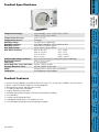
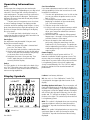
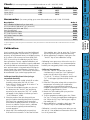
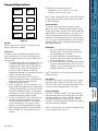
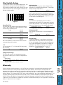
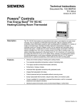
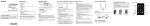
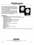
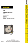
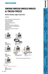
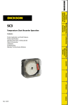
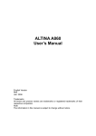
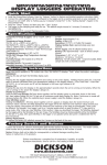
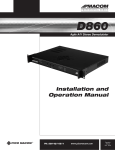
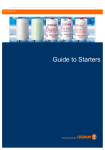
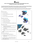
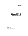
DICKSON
Product
Specifications
& Features
DICKSON
Temperature, Humidity & Dew Point Chart Recorder
Contents:
Charts &
Accessories,
Calibration
Instrument
Anatomy
Product Specifications & Features
Operating Instructions & Display Symbols
Charts & Accessories, Calibration
Instrument Anatomy
Getting Started / Installation
Keypad Operation
Dip Switch Setup & Warranty
Troubleshooting, Factory Service & Returns
Order Form
Operating
Information &
Display Symbols
THDx
Getting
Started/
Installation
Keypad
Operation
Dip Switch
Setup &
Warranty
Rev. 06/03
Troubleshooting
Factory Service
& Returns
DICKSON
930 South Westwood Avenue
Addison, Illinois 60101
Phone: (630) 543-3747 • E-mail: DicksonCSR@dicksonweb.com
DICKSON
Product Specifications
Product
Specifications
& Features
Keypad
Operation
Remote sensing capability with optional extension cords (10’, 50’ and 100’ available–see Accessories)
Alarms: Audio/Visual with High/Low setting capabilities
Microprocessor control and electronic sensing
C/F and RH/Dew Point switchable
Large 8” diameter circular chart
Min/Max feature allows display of minimum and maximum readings
User calibration
Locking control keypad and door
Large digital display shows two variables at once
User selectable recording times and temperature ranges
Getting
Started/
Installation
•
•
•
•
•
•
•
•
•
•
Instrument
Anatomy
Product Features
Charts &
Accessories,
Calibration
User Selectable: -20 to +120˚F (-20 to +50˚C),
+40 to +110˚F (+5 to +40˚C)
Temperature Accuracy:
±1.8˚F (±1.0˚C)
Temperature Sensor:
Thermistor
Humidity Range:
0 to 95% (non-condensing)
Humidity Accuracy:
±2% from 0 and 60%, ±3% from 60 to 95%
Humidity Sensor:
Monolithic IC humidity sensor
Dew Point Range:
-22 to +122˚F (-30 to +50˚C)
Dew Point Accuracy:
95% to 30% RH
±2˚C, ±3.6˚F
30% to 10% RH
±4˚C, ±7.2˚F
10% to 5% RH
±8˚C, ±14.4˚F
5% to 0% RH
±49˚C, ±88.2˚F
Ambient Operating Conditions: 32 to +122˚F (0 to 50˚C), 0 to 95% RH (non-condensing)
Display Resolution:
LCD, 1˚F (1˚C), 1% RH
Chart Size:
8” (20.3 cm) DIA
Recording Time: User selectable: 24 hour, 7 day or 31 day
Average Response Time:
2.5 min. for 63% of full scale
NOTE:
Response time is slower when using battery
Calibration:
User calibration of all variables
Operating
Information &
Display Symbols
Temperature Ranges:
Dip Switch
Setup &
Warranty
Troubleshooting
Factory Service
& Returns
Rev. 06/03
Alarm is on.
Rev. 06/03
MAX: This symbol is displayed when you are setting
a minimum alarm or when you have pressed the
“MIN/MAX” key and the maximum value it being
displayed.
Troubleshooting
Factory Service
& Returns
B 4
Figure
MIN: This symbol is displayed when you are setting
a maximum alarm or when you have pressed the
“MIN/MAX” key and the maximum value is being
displayed.
Dip Switch
Setup &
Warranty
Reading Update Indicator: These rectangles will
flash along the bottom of the display as long as the
recorder is taking readings. If you are using batteries
as the power source the update indicator rectangles
will still flash but the rate will be very slow in some
modes and “B” will light on display. The rectangle
furthest to the right is lit continuously when the unit
is using battery power.
���
���
E
UC: the unit is in “User Calibration” mode. This
is displayed in the upper right hand corner of the
display.
Keypad
Operation
���
Getting
Started/
Installation
�������
Lo Batt: Low battery indicator
Instrument
Anatomy
Display Symbols
Charts &
Accessories,
Calibration
Probe
The THDx probe sits in the cradle in the back of the
unit. The THDx probe comes with the standard 8”
cord. An extension cord can be ordered to allow for
remote sensing capabilities.
Power Supply
We recommend using AC power with four “D”
batteries installed as a back-up power source. This
ensures that your recording will not be interrupted
when there is a power failure. When the instrument
is using battery power, the unit will update very
slowly to extend battery life. The 120V AC adapter
plugs into the back of the recorder beneath the
probe cradle.
Operating
Information &
Display Symbols
Pen Adjust
Pen adjustment may be needed if the pens and
display do not match exactly.
1. Make sure the pen lifting bar is lowered and
press the “Pen Home” key.
2. Turn the chart hub clockwise, rotating the chart
3. With a small screwdriver loosen the pen adjust
screw on the pen arms and adjust the pen tips
to the outer most circle on the chart.
4. Retighten the screws. After pressing “Pen
Home” again the pens should now read
correctly with the display.
Cord Installation
If you have ordered an extension cord for remote
sensing capabilities follow the instructions for cord
installation listed below.
1. Turn the unit upside down or on its side so that
you can see where the probe connects to the
back of THDx.
2. Twist and pull the black rubber strain relief,
beginning on the back of the recorder body
(see “Instrument Anatomy”).
3. Slide the strain relief on the cord
4. Inside you will see a standard connector which
looks like a phone jack. Using a small screwdriver, press retention tab and the connector
will pop out easily.
5. Remove wand from cradle by sliding upward.
Repeat steps 1 through 3 for the portion of the
cord that connects to the wand.
6. Return the wand to the cradle mounted
position by sliding the wand down into the
cradle until it fits into the grips. The probe can
also be replaced by positioning it in back of the
cradle area pressing it into the cradle until it
snaps in place.
Product
Specifications
& Features
Pens
The blue pen has a longer pen arm and records
humidity or dew point (depending on your dip switch
selection). The red pan has a shorter arm and records temperature. The pens are offset to allow the
red pen to glide under the blue pen. The blue pen
indicates the correct time and the red pen precedes
it by 3/16 of an inch.
The pens move in increments across the chart
as sensor readings change. The display provides
smoother and faster readings than the pens. At any
given time there may be a slight discrepancy in the
position of the pen and the reading on the display
due to hysteresis.
For visual spot checks the display is more accurate than the pen position but both are within the
stated specifications of the unit.
DICKSON
Operating Information
(for current pricing go to www.dicksonweb.com or call 1-800-323-2448)
Accessories
24 Hour Chart
C415
C476
C472
C478
7 Day Chart
C417
C477
C473
C479
31 Day Chart
C480
C481
C482
C483
(for current pricing go to www.dicksonweb.com or call 1-800-323-2448)
Order #
N300
N400
A834
P246
A860
A865
A866
A709
A867
Calibration
Calibrating in an open room, without the use of a
salt capsule or a chamber, is not recommended as
humidity can vary greatly within a very small area.
Dip Switch
Setup &
Warranty
Troubleshooting
Factory Service
& Returns
Calibration is stored in memory even after you turn
the unit off. User calibration information will not be
lost of AC power fails.
Keypad
Operation
Calibrate Temperature
1. Press the “On/Off” key and the up arrow
simultaneously to enter the “User Calibration”
mode. Use dip switch #3 to select °F or °C.
(°F=#3 off, °C=#3 on). The display should read
“UC” in the upper right hand corner of the
display.
2. Place the THDx probe, along with your precision
temperature instrument (your temperature
standard) into a controlled environmental
chamber allowing both instruments to completely
stabilize for approximately 1 hour.
3. Match the THDx reading with your precision
temperature instrument.
4. To raise temperature reading, press the “Alarm
Set” key. To lower the temperature reading press
the “Alarm On/Off” key. Each key press adjusts
the reading by 1°F.
5. When calibration is complete, simply press the
“On/Off” key to save calibrated changes.
Getting
Started/
Installation
Calibrate Humidity/Dew Point (using a
controlled chamber)
1. Turn the unit on and use dip switch #5 to select
humidity or dew point (RH=#5 off, Dew
Point=#5 on). Use dip switch #3 to select °F or
°C (°F=#3 off, °C=#3 on).
2. To activate the calibration mode, turn the unit
off. Now press the “On/Off” key and the up
arrow key at the same time. The “UC” symbol
will appear in the display to indicate you are in
“User Calibration” mode.
3. Place the probe of the unit along with your
precision relative humidity/dew point instrument
(RH/Dew Point standards) into a controlled
environment chamber and allow 15 minutes for
the unit to stabilize. For best results, calibrate
the unit at levels typically monitored during
normal operation.
4. Match the THDx reading with your precision
RH/Dew Point instrument. To raise the RH/Dew
Point reading, press the up arrow key. To lower
the RH/Dew Point press the down arrow key.
5. When calibrating is complete, simply press the
“On/Off” key to save calibration setting.
Instrument
Anatomy
Your instrument was carefully tested and calibrated
before being shipped from the factory. For greatest
accuracy, we recommend factory re-calibration every
6-12 months. Call customer service at (630) 5433747. If you wish to do calibration yourself, follow
these procedures. Factory supplied calibration salt
capsules or electronic instruments recently calibrated
at a certified lab are recommended. Sling psychrometers and instruments using mechanical sensing elements (human hair, wood elements, bimetals, etc.)
should not be used. NOTE: The unit does not have to
be recalibrated if you used a longer probe cord.
Charts &
Accessories,
Calibration
*to protect probe & increase life - please use dust filter in dusty environments or where RH exceeds 70%. Probe dust filter will slow down
response time.
Operating
Information &
Display Symbols
Description
NIST Traceable Calibration 3-pt. (new unit)
A2LA Accredited Calibration 3-pt. (new unit)
RH Calibration Kit (33% and 75%)
Pens (3 red/3 blue)
10’ Probe Extension Cable
50’ Probe Extension Cable
100’ Probe Extension Cable
Carrying Case
Probe Dust Filter (see note)*
Product
Specifications
& Features
Range
-20 to +120°F
+40 to +110°F
-20 to +50°C
+5 to +40°C
DICKSON
Charts
Product
Specifications
& Features
Operating
Information &
Display Symbols
Charts &
Accessories,
Calibration
Instrument
Anatomy
Getting
Started/
Installation
Figure 1
Probe
Strain Relief
Alarm Sound
Source
AC Adapter
Jack
Pen Lifting Bar
Keypad
Operation
Dip Switch
Setup &
Warranty
Troubleshooting
Factory Service
& Returns
Rev. 06/03
Timing Clip
Temperature
Pen
Humidity/
Dew Point Pen
Chart
Guide Clip
Pen Cap
Holders
Figure 2
DICKSON
Instrument Anatomy
Chart Hub
Your THDx recorder has been preset to operate using
the post popular settings.
7 day
°F
-20 to +120°F
°F and %RH
1. Plug in the AC adapter
2. Set the appropriate time by inserting a coin
After you get started using the “Quick Start
Instructions,” we recommend that you also read the
rest of the manual to ensure that you get the most
our of your instrument.
Requires 4 “D” size batteries for battery back-up.
Operating
Information &
Display Symbols
Pens and a chart have already been installed for your
convenience. All you need to do to start using your
THDx recorder with the settings listed above is follow these quick start instructions:
Product
Specifications
& Features
Recording Time:
°F/C:
Temperature Range:
Variables Recorded:
into the groove in the chart hub and turning
clockwise until the correct hour and day on
the chart is referenced to the timing clip (see
“Instrument Anatomy” if you need assistance
locating instrument parts).
3. Remove the protective pen caps
4. Press the “On/Off” key and the pens will move to
the current reading.
DICKSON
Getting Started
Chart Installation
Instrument
Anatomy
4. Set time by inserting a coin into the groove in the
chart hub and turning clockwise until the correct
hour (and day if applicable) on the chart is
referenced to the timing clip.
5. Lower the pen lifting bar so that the pen tips rest
firmly on the paper.
6. Press the pen home key to return the pens to
position. At the end of tone recording time cycle,
simply repeat steps 1-5, replacing the used chart
with a new one.
Charts &
Accessories,
Calibration
1. Press the “Pen Home” key to make pens move to
the outside of the chart.
2. Press the pen lifting bar to raise the pens.
Remove the recorded chart if present.
3. Place the new appropriate chart on the chart hub,
being certain that the edge of the chart slides
under the chart guide clips located at the outside
of the chart. NOTE: The chart should lay flat on
the dial face.
Pen Installation
Press the “Pen Home” key to return pen to the home position.
Use the “Pen Arm” lifter to raise the pens.
Simply slide used pen cartridge off and slide new one on. Lower pen arm lifter.
Press the “Pen Home” key to return pen to chart position.
Getting
Started/
Installation
1.
2.
3.
4.
Keypad
Operation
Dip Switch
Setup &
Warranty
Troubleshooting
Factory Service
& Returns
The defaults for alarm settings are:
Temperature: +40°F min to +110°F max
Humidity: 20% min, 80% max
ON/OFF
ALARM
SET
PEN
HOME
ALARM
ON/OFF
Figure 3
Pen Home
Press the “PEN HOME” key while the unit is operating and the pens move to the outside of the chart.
Press the “PEN HOME” key again and the pens will
return to current reading points on the chart.
Dip Switch
Setup &
Warranty
NOTE: If the unit does not respond to keypad, check
to see that dip switch #8 is off.
Keypad
Operation
Display Change
Press the “DISPLAY CHANGE” key and the display
will temporarily show the reading opposite of what
is being recorded (i.e. if dip switch #5 is off and
you are recording the RH, pressing the “DISPLAY
CHANGE” key will temporarily change the display to
show the dew point reading).
Getting
Started/
Installation
Troubleshooting
Factory Service
& Returns
Rev. 06/03
NOTE: Turning the unit off resets the minimum and
maximum values.
Instrument
Anatomy
Alarm Set
The alarm set keys are labeled with arrows that
point up and down. You can set a minimum and
maximum alarm for both of the two variables you
are recording.
1. To set the alarms press the “ALARM SET” key.
The MIN symbol will be displayed and the
temperature will flash. (Note: The alarm set
function always starts with temperature. If
you do not want an alarm to sound for
temperature readings set the alarms for points
that are outside of the range.)
2. Use the up arrow button to increase the
minimum temperature alarm setting and the
down arrow to decrease the minimum
temperature alarm setting.
3. Press “ALARM SET” key a second time. The
MAX symbol will appear and the temperature
will flash indicating that you can now set the
maximum temperature alarm. Use the same
procedure as in step 2 above for setting the
temperature maximum alarm setting.
4. Press the “ALARM SET” key a third time and
the MIN symbol will appear and humidity
(or dew point dip switch #5 is on) will flash.
Use the same process as in steps 2 and 3
above to set humidity and dew point alarm.
5. When you have set alarms for both variables
press “ALARM SET” a final time to lock in
settings.
MIN/MAX
1. Press the “MIN/MAX” key once and the
minimum values, during the recording time,
will be displayed for 7 seconds.
2. Press the “MIN/MAX” key again and the
maximum values, during the recording time,
will be displayed for 7 seconds.
3. Press the “MIN/MAX” key a third time during
this period and the display will show current
readings. The unit will always return to current
readings mode after 7 seconds.
Charts &
Accessories,
Calibration
On/Off
When you press the “ON/OFF” key the pens will
move to the correct reading.
Alarm ON/OFF
This button turns the alarms on and off. When
alarms are “ON” the alarm symbol appears on the
display. When alarm sounds it will sound audibly for
approximately 1 minute and then it will stop. For a
visual, the variable that has moved outside of the
minimum or maximum points that you set will flash
(i.e. if you set a maximum alarm for +80°F and temperature reaches +80°F the temperature portion of
the display will flash).
Operating
Information &
Display Symbols
DISPLAY
CHANGE
Product
Specifications
& Features
NOTE: Alarm settings will return to the default when
AC power fails and there are no batteries installed
for back-up power.
MIN/MAX
DICKSON
Keypad Operation
1
2
3
4
5
6
7
8
Keypad Lock
For security purposes it is possible to lock the key
pad with the use of dip switch #8. You may want
to lock the keypad to prevent unauthorized persons
from using the keypad to set alarms or change the
calibration. (For more information on use of the
keypad see “Keypad Operations” on pg. 5.)
Keypad Unlocked
#8 off
Keypad Locked
#8 on
Keypad
Operation
Temperature Range
The THDx will record in two temperature ranges.
Dip switch #4 allows you to select the temperature
range.
Wide Range
-20 to +120°F (-20 to +50°C) #4 off
Narrow Range
+40 to +110°F (+5 to +40°C) #4 on
Getting
Started/
Installation
°F/C
You can record in °F or °C with the THDx by using
dip switch #3.
°F
#3 off
°C
#3 on
Display On/Off
Dip switch #7 will allow you to turn the display on
and off.
Display On
#7 off
Display Off
#7 on
Instrument
Anatomy
Recording Time
The THDx has four different recording time options:
1 day, 7 day, 14 day and 31 day. Dip Switch #1 and
#2 control the recording time.
7 day
#1 off
#2 off
1 day
#1 off
#2 on
14 day
#1 on
#2 off
31 day
#1 on
#2 on
NOTE: Remember to install correct chart to match
corresponding switch setting.
Charts &
Accessories,
Calibration
Figure 5
Display
The THDx has a dual display that shows both
temperature and humidity (or temperature and dew
point if dip switch #5 is on). With dip switch #6 you
can control the position of the variables displayed.
Temperature on top
#6 off
Temperature on bottom
#6 on
Operating
Information &
Display Symbols
Off
RH/Dew Point
Dip switch #5 allows you to select whether RH or
dew point is recorded by the blue pen. (The red pen
always records temperature.)
RH
#5 off
Dew Point
#5 on
NOTE: When the blue pen is recording dew point,
the reading indicates the temperature at which dew
will form, so you should use the temperature scale
on the chart to read dew point.
Product
Specifications
& Features
To set-up the THDx for your specific application, you
might need to change some of the Dip Switches.
Every time you change a dip switch setting, you must
push the up arrow key on the keypad to activate the
new dip switch settings.
DICKSON
Dip Switch Setup
Warranty
Troubleshooting
Factory Service
& Returns
Rev. 06/03
Dip Switch
Setup &
Warranty
Dickson warrants that the products it sells will be free from defects in material and workmanship under
normal use and service for a period of twelve months after delivery. In the event of a claim under this
warranty, the product or part must be returned to the factory for repair or replacement (shipping pre-paid)
with a Return Authorization Number (see Return Information above). It will be repaired at Dickson’s option
without charge. This warranty DOES NOT cover routine calibration, pen, chart and battery replacement. The
foregoing warranty and remedy are exclusive and in lieu of all other warranties either expressed or implied.
Dickson shall not be liable for consequential or incidental damages resulting from failure or malfunction of
its products. Dickson makes no warranty for products not manufactured by it or for any products modified by
buyer, or subject to misuse or neglect.
Problem
Temperature Pen & Display do not match
Instrument turns off
Charts &
Accessories,
Calibration
Instrument
Anatomy
Getting
Started/
Installation
Display shows dc and indicator on the left
part of the digital display
Display shows E (lower left of digital display) • System error or error in calibration, send to Dickson
Out of calibration or questionable accuracy
• Instrument exposed to harsh environments or stressful
conditions, see “Calibration” procedure in manual
• Return to factory for re-calibration
Display won’t light up
• Check dip switch #7, switch should be off
Unit won’t work at all
• Check both dip switch #7 & #8. Both should be off to
allow operation
Pen trace too fine or absent
• Pen may need to be replaced, moistened, or sanded
• Remove pen cap
Display shows Err
• Temperature being monitored is too high, see pg. 2
Display shows Prob
• Temperature being monitored is extremely cold or probe
is disconnected
Display shows cold
• Temperature being monitored is too low, see pg. 2
Display shows frozen
• Reset the unit by shutting it down (unplug the AC adapter
and take the batteries out) then restore power source and
turn it on
Operating
Information &
Display Symbols
Probe exposed to environments exceeding
95%RH for extended period
Alarm symbol is flashing in digital display
Product
Specifications
& Features
Instrument is not responding to key presses
Solution
• Check dip switch setting & proper chart
• May also be hysteresis, see page 4, “Pens”
• Need for pen adjustment, see page 4, “Pen Adjust”
• Keypad may be locked, check dip switch #8
• Slower, firmer key presses (may take multiple presses)
• Check AC adapter connection (widen prongs of adapter to
fit together)
• Display may be off, check dip switch #7
• Probe should be dried out under normal ambient conditions
–time required varies on temperature, RH and air flow
• Alarm sounds audibly for 60 seconds if out of range
conditions occur, then indicator will flash until alarm key is
depressed and alarm is reset (depress MIN/MAX keys for
information)
• Factory repair is necessary, send to Dickson for repair
DICKSON
Troubleshooting
Factory Service & Returns
NOTE: Dickson shall not be liable for consequential or incidental damages resulting from failure or malfunction of
its products.
Software Return Policy
IMPORTANT-Read your Software License Agreement carefully before installing software. DIckson will accept
returns for replacement of defective disks and CDs only.
Troubleshooting
Factory Service
& Returns
Customer Satisfaction
Dickson takes pride in providing you, the customer, with the highest quality instrumentation. We welcome the
opportunity to help you in any way possible. Whether it be a question or a new idea in documentation, the Dickson
Company would like to hear your response. Please call our Customer Service Department at 1-800-323-2448 or
(630) 543-3747 (in Illinois).
Dip Switch
Setup &
Warranty
• Carefully repack the instrument, label the outside of the box with the RA# and return the instrument
(freight pre-paid) to Dickson.
• All instruments that do not have the RA# clearly marked on the outside of the box will be refused. When
returning instruments for credit, please include all accessories in shipment.
• Calibration/Freight charges are non-refundable.
Keypad
Operation
Contact the factory (630-543-3747) for a Return Authorization (RA) Number before returning any instrument. The
model number, serial number and a purchase order number will be requested before an RA number is issued.
Mail to: Dickson, 930 S. Westwood Ave, Addison, IL 60101
Step 1 - Bill To:
Product
Specifications
& Features
Name
Company
Address
City
State
Phone (
Email
Zip
)
–
Operating
Information &
Display Symbols
Step 2 - Ship To (if different than above)
Zip
)
Order #
–
Total
$
$
$
$
$
$
$
$
Instrument
Anatomy
Getting
Started/
Installation
Step 3 - Ordering Information
Quantity
Price/Unit
$
/each
$
/each
$
/each
$
/each
Subtotal:
In Illinois, add 7.5% sales tax 4
Tax:
Freight:
All Prices in U.S. Dollars 4
Total:
Charts &
Accessories,
Calibration
Name
Company
Address
City
State
Phone (
Email
Step 4 - Payment Method
–
Expires: (mm/yy)
/
–
Keypad
Operation
Check: Check #
Money Order
Credit Card:
Credit Card Number:
–
Signature
(Net 15 days for established customers)
U.S.A. Freight Charges
UPS Next
$31
$39
$53
$56
$72
$91
UPSGround
$9
$14
$17
$24
$36
$43
Troubleshooting
Factory Service
& Returns
Total Order
UPS 2nd Day
$0-100
$15
$101-400
$19
$401-700
$26
$701-1,000
$35
$1,001-1,500
$52
$1,501-2,000
$69
$2,001-over Please call Dickson Customer Service
All shipments UPS 2nd day unless otherwise requested.
Dip Switch
Setup &
Warranty
Purchase Order: P.O.#
Customer #:
DICKSON
Fax to: 1-800-676-0498