1
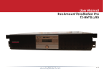
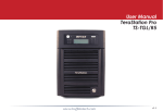
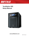
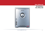
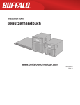
www.buffalotech.com
User Manual
TeraStation iSCSI
TS-ITGL/R5
v1.4
Introduction
Congratulations on your new TeraStation! Your TeraStation iSCSI is a huge block of iSCSI
storage, ready to add to your server or PC via ordinary wired Ethernet connections. This
guide will help you configure it.
There are many ways to configure and use iSCSI storage products like the TeraStation. In
this guide we give one example of configuring a simple iSCSI volume on a single workstation.
Many other configurations are usable.
Because we’re constantly updating our product, the images and text in this manual may vary
slightly from the images and text displayed by your TeraStation. These changes are minor
and should not affect the ease of setup adversely. As time passes, future user interfaces,
updated software, and later versions of this manual may be available for download at our
web site: www.buffalotech.com.
If you run into difficulties or need additional help, feel free to contact our technical support.
Contact information for Buffalo Technology and our technical support is available on pages
47 and 48.
Table of Contents
TeraStation Layout............................................................4
Installation........................................................................7
Configuration GUI . ......................................................... 15
Login........................................................................ 16
IP Address................................................................ 20
RAID Settings........................................................... 22
UPS.......................................................................... 27
Alerts........................................................................ 29
Troubleshooting............................................................... 39
Replacing a Hard Drive.................................................... 41
Technical Specifications................................................... 46
Technical Support............................................................ 47
GPL Information.............................................................. 49
Layout
Display Mode Switch
Power Switch
Door opens for access
to hard drives.
Door Lock (Turn counterclockwise to release)
Layout
Init Button returns
settings to factory
defaults.
Hard Drives
(Squeeze tabs to release)
Layout
Power Cable (to outlet
or surge protector)
USB in
Ethernet (to NIC,
Router, or Switch
UPS
Installation
Begin by connecting your TeraStation’s power and Ethernet cables. The Ethernet cable should be
connected to an extra NIC on your server or to a router, hub, or switch on your network.
For best performance, all network equipment should be gigabit or better. Use a NIC with enough
RJ-45 ports for all your iSCSI devices, or separate NICs for each iSCSI device. Assign static IP
addresses for each iSCSI device. Bridge the ports for all the NICs in the server (including the LAN
connection). Statically assign the IP address for the LAN to the “Bridged” connection, not on the
actual NIC for the LAN. Provided uninterruptable power supplies for all iSCSI devices, as well
as the server itself. Simpler configurations may work, but this kind of uncompromising setup is
recommended for best performance and reliability.
After all connections are made, turn the TeraStation on by pushing the power button on the front
panel. It will take about a minute to boot.
Insert the TeraNavigator CD into your computer’s CD-ROM drive.
On a PC, setup should automatically launch. If it does not, manually
launch setup.exe by pressing Start and selecting the Run... option.
When the Run dialog opens, type d:\TSnavi.exe (where d is the drive
letter of your CD-ROM drive). Press OK to continue.
Installation
Press the Begin Installation button to begin.
Easy Setup will step you through physically connecting your
TeraStation. It will then install software.
Advanced Setup skips the connection tutorial and goes
directly to installing software.
Installation
If your TeraStation is connected correctly when you get
to this window, it will be highlighted in the drop-down
list. If you have multiple units to set up, select the correct
TeraStation from the list.
Select First Setup for the initial installation.
To install the software on additional computers, chose
Additional Setup.
Installation
Once the TeraStation is installed, you’ll need to install
the iSCSI connection tool. Click Next, then continue to
click Next, stepping through the menus until the iSCSI
connection tool is installed.
Click Yes to launch the iSCSI connection tool.
10
Installation
Make sure that your ISCSI TeraStation is selected in the
Target product window. Click Register the iSCSI Hard Disk,
and then OK.
If the TeraStation has more than one volume, choose
the volume you want to connect to from the drop
down list. Check Resume connection at start up.
Click Connect. Repeat to add additional volumes if
desired.
11
Installation
If Disk Management does not open automatically, you may launch
it manually. From the Setup menu at the top of the window,
choose Launch Disk Management.
Each connected volume from your ISCSI TeraStation now
appears as a hard drive in Disk Management.
12
Installation
The Initialize and Convert Disk Wizard will
open. Use it to convert your new volumes
to dynamic volumes. Put a checkmark next
to each of your disks and click Next to step
through the menu.
Right-click on the volume in Disk Management
and click New Volume to start the New Volume
Wizard. Click Next.
13
Installation
Choose your desired volume type. Use Simple if
you have only one volume to mount. Spanned and
Striped volumes require multiple disk volumes to
create. Click Next when ready.
Add all dynamic disks that will be included in the
volume to the Selected column by highlighting them
and then clicking the Add button.
14
Installation
Choose your desired drive letter. Click Next.
Choose your desired format and volume label. Click Next.
Your new volume is installed and ready to use!
15
Configuration GUI
The Configuration GUI is where most of the
TeraStation’s settings can be changed.
To access it, type the IP address of your TeraStation
into the URL bar of a browser running on a
computer connected to the same network as the
TeraStation.
16
Advanced Settings
The login prompt will appear. Enter admin for the user name. Until you change it, the password
for the admin account will be password. Press the OK button when finished.
User name: admin
Password: password
17
Configuration GUI
Welcome to the configuration GUI for the TeraStation!
You are now at Home. Notice that the Home button is lit up in yellow. You can navigate this menu
by clicking on the buttons at the left of the screen. Here at “Home”, you can see basic information
about your TeraStation’s current configuration. You may close this screen by clicking Logout at the
bottom left, or just by closing the browser window. If you have lost your TeraStation, clicking I’m
here! at the bottom left will cause it to beep, making it easier to find.
Note that many settings cannot be changed while the iSCSI service is running. Click the button
in the top left corner of the page to disable the iSCSI service if settings need to be changed.
18
Configuration GUI
Basic
You may modify your TeraStation’s hostname
and description under Hostname Setup.
A friendly, easy-to-remember name (e.g.
“TeraStation”) is recommended.
Make sure that the date and time are correct
in Date and Time Setup. To synchronize time
settings with those in your computer, press
Use Local Time. To have your system time
automatically set by an NTP server, enable NTP
Server and enter an IP Address for the NTP
server (e.g. 192.43.244.18) or use the supplied
default NTP server.
Ensure that both the Display Language and the
Windows Client Language are set to languages
that you’re comfortable with.
Once desired fields have been completed, press
the Apply button.
19
Configuration GUI
Admin Password
By default, the admin password is “password”.
Change it to something more secure here.
20
Configuration GUI
Network (IP Address Properties)
In most networks, TeraStation will get its IP
Address automatically from a DHCP server.
You may disable DHCP here. If DHCP is
disabled and an IP Address is not set manually,
it will default to 192.168.11.150. The
TeraStation’s IP Address, Subnet Mask, Default
Gateway Address, and DNS Server address
may all be entered manually under IP Address
Properties.
Ethernet Frame Size may also be set manually
on this page. Only use JumboFrame settings
when operating in a Gigabit environment where
all other clients support the same JumboFrame
setting.
Click Apply after making any changes.
21
Configuration GUI
Disk Management (Drive Properties)
This page shows the current properties of your hard drives
and RAID Arrays. To change these settings, click on RAID
Setup at left.
22
Note on RAID Arrays
TeraStation uses RAID (“Redundant Array of Independent Disks”) technology to control the four
hard drives in your TeraStation. RAID may be configured several ways:
RAID 0 - All four drives are combined into one large, fast drive, giving the maximum capacity for
your TeraStation. This size is the one listed on your TeraStation’s box and shows the total capacity
of the TeraStation with no data used for redundancy. RAID Spanning is fast and efficient, but with
no redundancy, if one hard drive fails, all data on the TeraStation is lost.
RAID 1 (mirroring) - Hard drives are arranged in mirrored pairs. Each half of the pair reads and
writes exactly the same data. This costs you half the total capacity of the array, but provides
excellent redundancy. If a hard drive fails, the mirror continues to supply data, so you may work
on normally. You may replace the damaged or defective drive at any time, and normal RAID 1
mirroring will then be automatically restored.
RAID 5 (parity) - All drives in a RAID 5 array reserve part of their data space for parity information,
allowing all data to be recovered if a single drive fails. The parity information takes up about one
hard drive’s worth of space, so if you set up all four drives in the TeraStation as a RAID 5 array,
your usable capacity will be about 3/4 of the total capacity of the TeraStation. This is how your
TeraStation is set up out of the box.
RAID 10 - Combines RAID 1 and RAID 0 for a fast, secure array. Half of the TeraStation’s total
capacity is used for redundant information.
Buffalo Technology recommends RAID 5 for its excellent balance of efficiency and security.
23
Configuration GUI
Disk Management (RAID Setup)
This page shows your current RAID arrays. You may delete
old arrays or create new ones by clicking on the underlined
RAID Array # under RAID Array Configuration.
The RAID Scanning Settings set a specific time for the
TeraStation to scan and inspect its RAID arrays. It is
recommended to set a time where the TeraStations
usage will be minimal (perhaps the middle of the night).
TeraStation will be significantly slower while the RAID
scan occurs. Begin Immediate RAID Scan specifies the
TeraStation to run a RAID Scan immediately.
You may also disable RAID Array Error Detection Response from this page. Normally, this is set to
automatically shut down the RAID array when an error is detected. Though it is not recommended,
you may disable that behavior by selecting Disable.
NOTE: TeraStation has four internal hard drives. Before creating a new RAID array, you may have
to delete one or more pre-existing RAID Arrays to clear up the hard drives for your new one. This
will destroy all data currently on the disks, so back up any important data before deleting RAID
arrays. Whether you want to clear out an old array or create a new one, begin by clicking on the
array’s underlined RAID Array #, under Name.
24
Configuration GUI
Disk Management (Disk Erase)
Disk Erase removes all data from the selected
disk. This may take several hours to complete. It
cannot be undone.
25
Configuration GUI
Volume Settings
Here you can enable or disable
volumes, shares, and folders.
26
Configuration GUI
Maintenance (Notification)
If your TeraStation is remotely managed, you
may choose to receive nightly status reports
and be notified of any disk events by email.
To set this up, enable Mail Notification and
enter the IP Address of your SMTP server*
in the SMTP Server Address field. Select a
Subject line for the emails (i.e. “TeraStation
Status Report”) and enter the email address of
each person you want to receive notification
emails into a Recipient Mail Address field.
27
Configuration GUI
Maintenance (UPS Settings)
You may enable Synchronize with UPS
and UPS Shutdown Conditions from this
page. Consult your Uninterruptable
Power Supply’s documentation for further
information about setting up your UPS
system.
Buffalo Technology recommends the use
of APC SmartUPS Serial Uninterruptable
Power Supplies. Other UPSs may use
different pin configurations. Compatibility
cannot be guaranteed with other UPSs.
Turn to the next page for more on the
TeraStation’s UPS serial port.
28
UPS Configuration
Maintenance (UPS Settings)
This is TeraStation’s serial port pin
assignment for serial UPS products.
29
Configuration GUI
Maintenance (Alert Settings)
Alerts can be configured on the TeraStation to make audible noises when a problem is detected.
Along with the audible noise, alert emails will be sent out if Mail Notification was properly configured.
Please select the features you would like to receive an audible sound alert from and then press the
Apply button.
30
Configuration GUI
Maintenance (Status LCD)
The Status LCD Setup allows configuration for
the LCD display on the front of TeraStation.
Please select the type of information that the
front panel should display from the LCD Display
Items. Automatically Switch LCD Items tells
the TeraStation to cycle through the selected
display items every 10 seconds. Disabling this
feature means the LCD display does not cycle,
and it will stay on the same display item until
the Display button on the front of TeraStation
is pressed. The LCD screen and green LED
buttons brightness can be controlled via their
respective settings. Press the Apply button once
all of the settings have been configured.
31
Configuration GUI
Maintenance (Syslog Transfer)
Check Enable to allow system logs to be
transferred. Press Apply once all of the
settings have been configured.
32
Configuration GUI
Maintenance (Shutdown)
From the Shutdown page, press
Apply to shutdown TeraStation. This
has the same function as holding
down the power button on the front
of TeraStation, but may be done
remotely. Turning on the TeraStation
after a shutdown requires a
physical button push on the front of
TeraStation. The Restart Now button
simply reboots the TeraStation,
bringing it back to functionality after
about 120 seconds.
33
Configuration GUI
Maintenance (Initialization)
Initialization is a reset procedure that restores
all settings back to the default, out of box,
configuration. All configuration, users, groups,
and backup jobs are lost, but actual data and
shares on the hard are NOT lost. If you want
all data to be erased, reformat the drive.
Specify whether the TeraStation shall keep its
administrator password after a initialization
or whether the password should be reset to
the default password (default password is
password). Press the Apply button once you
make the selection.
Press the Restore button to begin the initialization process; this will restore all settings to factory
defaults but does NOT erase the data on the hard drives.
34
Configuration GUI
This page shows you the System Information for your TeraStation.
Firmware updates are occasionally available from www.buffalotech.com for the TeraStation Pro.
These must be executed from a Windows PC on the same network. Your router, switch, or hub
should pass through ports 8873 and 22939 for this to work (most do).
35
Configuration GUI
System Status (USB Details)
This page shows you details on USB hard drives and UPSs plugged into your TeraStation.
36
Configuration GUI
System Status (Drive Properties)
This page shows you the properties of all hard drives and
RAID arrays in and attached to your TeraStation.
37
Configuration GUI
System Status (Network Information)
This page shows you the System Information for your network connection.
38
Configuration GUI
Log Information
This page lets you save or display system log information. Choose the log you want from the Log
Type dropdown and click Save. The dialog will let you save or display (“Open”) the logfile.
39
Troubleshooting
If TeraStation encounters a disk error, it will be reported in the TeraStation status on the top of
any of the Web-Based configuration screens. Run a Disk Scan in the event of this error. If that
does not resolve the problem, a format is recommended. Formatting the drive will delete all of the
data on it, so back up any data you can before formatting. Finally, if none of the above solutions
help, then please contact Technical Support (see pages 73 and 74 for Technical Support contact
information).
40
Troubleshooting
DIAG LCD Codes:
Error Code
E00
E01
E02
E03
E04
E10
E11
E12
E13
E14
E15
E16
E17
E18
E19
E20
E21
E22
E23
Description
Alert
MPU error: Main MPU is not responding.
Error on DRAM DATA LIN
Error on DRAM ADDRESS LINE
Error on RTC CHIP
Failed to load kernel (FLASH error)
UPS AC LINE FAIL Error
FAN Error: Fan rotation speed is low or fan is stopped.
Cooling Error: Cooling by fan cannot catch up.
Error has occurred on RAID Array x.
Cannot mount RAID Array x.
Not Used
Cannot find HDDx.
Cannot communicate with RTC chip (IC12).
Cannot communicate with SATA chip (IC1).
Cannot communicate with SATA chip 2 (IC2)
Cannot communicate with USB chip (IC5)
Cannot communicate with Ethernet chip (IC13)
Cannot mount HDDx
HDDx faulty (HDDx is excluded from raid because of errors)
41
Sound
A
A
A
A
A
B
B
B
B
B
B
A
A
A
A
A
B
B
Replacing a Hard Drive
Turn the key counter-clockwise to open drive door.
Squeeze the tabs gently and swing
the tray latch upward.
The hard drive tray will now slide out.
42
Lower the drive carefully to the work surface.
Gently push down on the two tabs to release the plug.
43
Pull the plug straight out to
remove the drive.
To remove the hard drive from
its cage, set the assembly on a
soft surface and remove these
four screws.
44
Install a new hard drive by doing the same steps in reverse order:
Begin by screwing the new hard drive into the cage.
Plug the power/data connector into the hard drive.
Slide the hard drive cage back into the TeraStation.
Press the latch down to lock the hard drive cage in place.
45
Technical Specifications
LAN Standards:
IEEE 802.3u 100BASE-TX; IEEE 802.3 10BASE-T
Transmission Types:
1000Mbps/100Mbps/10Mbps; 100BASE-TX
4B/5B, MLT-3;10BASE-T Manchester Coding
Access Media:
CSMA/CD
Media Interface:
RJ-45
USB Standard:
USB 2.0
Hi-Speed (HS)
Full-Speed (FS)
Low-Speed (LS)
USB Connector:
USB A Connector (2)
Data Transmission Speed:
Max: 480 Mbps (HS Mode)
Max: 12 Mbps (FS Mode)
UPS:
UPS Compatible (Serial/USB connection)
Power Consumption:
~56W (Varies based on size)
Dimensions:
6.7” x 9.3” x 12.2” (170 x 235 x 310 mm.)
Weight:
~15.8 lb (7.2 kg) (Weight varies based on size)
Operating Environment:
32° - 95° F; 20-80% non-condensing
46
Contact Information (North America)
Buffalo Technology USA Inc.
11100 Metric Blvd, Suite 750
Austin, TX 78758
GENERAL INQUIRIES Monday through Friday
8:30am-5:30pm CST
Direct: 512-794-8533 | Toll-free: 800-456-9799 | Fax: 512-794-8520 | Email: sales@
buffalotech.com
TECHNICAL SUPPORT North American Technical Support by phone is available 24 hours a day, 7 days a week. (USA
and Canada).
Toll-free: (866) 752-6210 | Email: info@buffalotech.com
47
Contact Information (Europe)
Buffalo Technology UK Ltd.
2 Bracknell Beeches, Old Bracknell Lane
Bracknell, Berkshire, SL1 4RD
United Kingdom
GENERAL INQUIRIES Email: sales@buffalo-technology.com
TECHNICAL SUPPORT Buffalo Technology provides technical support in English, German, French, Italian, and
Spanish. For opening hours and relevant telephone numbers, please go to
www.buffalo-technology.com/contact
48
GPL Information (North America)
Thank you for your interest in Buffalo products. Our GPL software delivery policy is outlined below.
For each individual product and revision, please send one individually packaged self addressed padded CD
shipping envelope, containing a blank CD-R to the following address:
Buffalo Technology USA Inc.
11100 Metric Blvd., Suite 750
Austin, TX 78758
Attn. GPL Department
Within the envelope containing the self addressed padded CD shipping envelope, please include a bank draft
or money order for $20 (USD) (Made out to: Buffalo Technology) to cover our handling fee, postage and CD
preparation. The CD-R should have the name of the product and revision number clearly written on the
actual CD-R (not on the insert).
We do not send GPL source in bulk on a DVD. And order confirmation is not required by the GNU General
Public License.
We are more than happy to comply with your request; however, we must ask you to comply with our GPL
distribution policy, which complies with the GNU General Public License.
Sincerely,
Buffalo Technology GPL Department
49
GPL Information (Europe)
Thank you for your interest in Buffalo products. Our GPL software delivery policy is outlined below.
For each individual product and revision, please send one individually packaged self addressed padded CD
shipping envelope, containing a blank CD-R to the following address:
Buffalo Technology Ireland Ltd
Free Zone East, Shannon, Co. Clare
Ireland
Attn. GPL Department
Within the envelope containing the self addressed padded CD shipping envelope, please include a bank draft
or money order for €20 (Euro) (Made out to: Buffalo Technology) to cover our handling fee, postage and CD
preparation. The CD-R should have the name of the product and revision number clearly written on the
actual CD-R (not on the insert).
We do not send GPL source in bulk on a DVD. And order confirmation is not required by the GNU General
Public License.
We are more than happy to comply with your request; however, we must ask you to comply with our GPL
distribution policy, which complies with the GNU General Public License.
Sincerely,
Buffalo Technology GPL Department
50