1
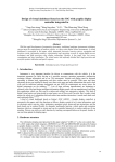
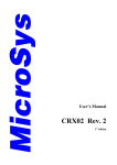
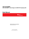
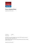
Display Controller Block in
Fujitsu’s GDCs: SALIENT FEATURES
1
Display Controller Block in Fujitsu’s GDCs: SALIENT FEATURES
TABLE OF CONENTS
1.
INTRODUCTION AND OVERVIEW ................................................................... 3
2.
DISPLAY FUNCTION............................................................................................. 4
2.1.
2.2.
2.3.
2.4.
3.
WINDOW AND COMPATIBILITY LAYER MODES .................................................... 4
CONSTRAINT ON THE NUMBER OF LAYERS DUE TO LIMITED MEMORY ................ 4
OVERLAYING MECHANISM .................................................................................. 5
SIMPLE PRIORITY AND ALPHA BLEND MODES FOR OVERLAY ............................. 6
DISPLAY PARAMETERS – WHAT THEY REALLY MEAN .......................... 6
3.1.
Relationship between Display Parameters and Display Signal Timing.......... 7
4.
DISPLAY FRAME POSITION CONTROL.......................................................... 8
5.
DISPLAY COLOR MODES: DIRECT, INDIRECT, AND YCBCR................ 10
6.
HARDWARE CURSORS ...................................................................................... 10
7. DISPLAY SCAN CONTROL: RESOLUTION, CLOCKS AND
FREQUENCIES.............................................................................................................. 10
8.
PROGRAMMABLE YCBCR CONVERSION OF VIDEO CAPTURE LAYER
11
9. SYNCHRONOUS REGISTER UPDATE – ENHANCING SMOOTH
ANIMATION .................................................................................................................. 12
10.
DUAL DISPLAY FUNCTIONALITY.............................................................. 12
10.1.
DESTINATION CONTROL................................................................................. 12
10.2.
DUAL DISPLAY FOR CORAL-PA..................................................................... 13
10.2.1. Dual Display: Output Signal Control............................................................ 13
10.2.2. Output Circuit Examples............................................................................... 14
10.3.
DUAL DISPLAY FOR LIME: ............................................................................. 16
10.4.
CONSTRAINTS ON THE USE OF DUAL DISPLAY FUNCTIONALITY\................... 16
11.
SUMMARY ......................................................................................................... 17
12.
ACRONYMS ....................................................................................................... 17
2
1. Introduction and Overview
Fujitsu graphics controllers have long been a mainstay in the world of automotive
navigation units, owing in large part to the attractive mix of features at a modest budget –
both in terms of fiscal and power. For example, Fujitsu’s latest Graphic Display
Controller (GDC) chips, Coral-PA and Lime, feature a display controller block that is
capable of supporting six layers and up to XGA (1024 x 768) resolution in Coral. In
Lime, the maximum resolution is 1280 x 768. They also include dual display capability
that is a very useful attribute as automakers continue to increase their marketing focus on
seat-back entertainment. In addition, the display controller blocks for both of these
devices support double buffering and window scrolling for ultra smooth image quality
and to provide the user with a unique level of display flexibility.
This paper will focus on the display controller block, which is a key differentiator for
Fujitsu graphics products. From this point onwards, this note will refer to “Display
Controller Block” as simply “Display Controller.”
Let’s start out by loosely categorizing display controllers in a manner that is, admittedly,
somewhat arbitrary but reflect the way that many of our users view the product
segmentation. A very basic GDC would consist of a simple frame buffer memory and a
display controller to generate the display signal. The host controller can handle the
drawing function while manually modifying the display frame in the buffer. Then we can
realize a slightly more complicated display controller with a frame buffer, and a drawing
engine having some basic 2D functions such as line and polygon drawing. It may overlay
a two or maybe three layers; while implementing alpha blending (transparency) between
the layers. The third category GDC overlays many layers (four to six), implements both
layer alpha blending and alpha-plane, hardware cursors, and is assisted by a drawing
engine having full featured 2D drawing functions (shading, texture mapping, antialiasing, primitives, polygon fill etc.). It also has a video capture function and a multidisplay capability. The forth category GDC adds a 2D/3D graphics engine, along with a
geometry processor and a drawing engine that has a considerably higher draw rate as a
result of operating at faster clock speeds. The fifth and last category has additional multimedia functions, such as video and audio support at a processing level (decoding A/V
and not just capture and resize as is the case in the previous category), and its graphics
engine has advanced features such as fogging and lighting. This class of GDCs has the
highest draw rate. Lime falls in the third category, while Coral-PA occupies a space in
the forth one. Fujitsu’s new Carmine GDC, which will be introduced late in 2006, will fit
into the fifth category.
This note will focus on Lime and Coral-PA, as these are devices that are considered
mainstream or in the “sweet-spot” for today’s navigation design requirements. In other
words, these two devices provide an excellent cost performance ratio. Lime and Coral-PA
have both an analog/digital RGB video output interface. These chips can connect with
any type of LCD display panel (passive, active etc.) that has a matching RGB video and
timing signals. Therefore, this paper can focus on the display controller functionality
without any consideration for display properties, interface or other display attributes.
3
2. Display Function
2.1. Window and Compatibility Layer Modes
The display controller supports both six layer and four layer configurations, the latter
making it backward compatible with the previous Fujitsu GDC products such as Cremson
and Scarlet. This point is important only in that it highlights a key attribute of a Fujitsu
product line and that is backward or upward compatibility thereby preserving the user’s
software investment. In the six-layer mode, also called the Window Mode, the overlay
sequence can be set in any order. In the Compatibility Mode, supporting up to four layers,
the overlay sequence is fixed. This is shown in Figure 1 below.
Figure 1: Configuration of Display Layers
Figure 1-b shows how the layers B, M, W, and C of the pre-Coral products are supported
with the compatibility mode. This makes it possible to transition from these parts to Coral
series with virtually no changes in Application Software.
2.2. Constraint on the Number of Layers due to Limited Memory
The maximum number of layers that can be used depends on the amount of graphics
memory available to the GDC. For example, for a display layer of size 800*480 and 16
bpp color depth, a memory area of 2*800*480= 768 kB is required. For more than one
such layer, this value will be multiplied with the total number of layers. There are also
some other factors to consider. Double buffering for smooth animation requires two such
frames to be stored in the memory for each layer, one for the drawing frame and the other
for the display frame. Moreover, a memory buffer of about 2 frames needs to be reserved
4
for using the Video Capture function. In short, if there is a limited amount of memory
available, then the number of layers will be limited accordingly.
Note: In addition to the above stated requirements for memory, some space in the
graphics memory will be required for Z-Buffer, Polygon Drawing Flag Buffer, Display
List Buffer, Texture Pattern, and Cursor Pattern.
2.3. Overlaying Mechanism
Figure-2 below shows the blow diagram of the layer overlay mechanism.
Figure 2: Layer Overlay Mechanism
As the Figure-2 shows, the fundamental process flow is Palette to Layer Selector and
then to Blender. The palette converts 8-bit color data in to RGB format. The Layer
Selector changes the overlay sequence in an arbitrary manner. The Layer Blender either
performs alpha blending using the coefficient defined for each layer or it uses the
transparent color definition to show the layers.
The GDC supports four color pallets or Color Look Up Tables (CLUT), namely Pallet 0,
1, 2, and 3. The CLUTs can be specified using register setting. Also, the Figure-2 points
out the cursor can be overlayed either above or below Layer 0.
5
2.4. Simple Priority and Alpha Blend Modes for Overlay
The layer overlay can be performed in one of the two modes: Simple Priority Mode and
Blend Mode.
In simple priority mode, the decision whether to display a pixel, upon performing layer
drawing, is made after comparing the new display color with the Transparent Color
definition. This mode is represented by the following equation,
Dview= Dnew; when Dnew does not match the transparent color
Dview= Dlower; when Dnew matches the transparent color
Dview is the pixel color to be shown and Dlower is the pixel color before performing the
layer drawing. This comparison is not performed for the L1 layer when it is being used to
show video capture contents.
The blend mode is defined by the following equation.
Dview= Dnew*r + Dlower*(1-r)
“r” is called Alpha Blending ratio and is an 8-bit value. Using this mode also requires the
MSB of the pixel value to be set to 1.
There is another mode called Blend Coefficient Mode, which uses the L5 layer as the
alpha blending coefficient values. This mode can be used to provide gradation effect in
alpha blending, e.g. to create spot light effect on the displayed graphics or to highlight the
area of interest in a navigation map.
3. Display Parameters – What they really mean
The display area is defined in terms of the following parameters:
6
Figure 3: Display Parameters
Each one of these is set in the respective register. VTR, VSW, VSP, VDP, HTP, HSW,
HSP, HDP, and HDB correspond directly with the display panel’s timing. The following
diagram shows how these values map onto the R/G/B, HSYNC and VSYNC signals for a
non-interlace display.
3.1. Relationship between Display Parameters and Display Signal Timing
7
Figure 4: Display Timing for a Non-interlace Display
These parameters are set once during the GDC’s software initialization. The following
relationship must be met for a proper display.
0 < HDB <= HDP < HSP < HSP+HSW+1 < HTP
0 < VDP < VSP < VSP+VSW+1 < VTR
In order to calculate these parameters, it is important to know details of display panel’s
clock and timing specifications.
4. Display Frame Position Control
8
The graphic image data to be displayed is located in the logical 2D coordinates space
(logical graphics space) in the graphics memory. There are six logical graphics spaces,
one for each layer.
The mapping between logical graphics space and display position is illustrated as
follows:
Figure 5: Display Position Parameter
For a further explanation please refer to Coral-PA user manual.
The display controller treats the logical graphics space as if it is rolled over in both the
horizontal and vertical directions. As a result, if the display frame crosses the border of
the logical space, the part outside the border is covered with the other side that is
assumed to be cyclically connected.
There are a few important relationships between logical graphics space and display
frame. Firstly, the expression of X and Y display coordinates and the corresponding
linear memory addresses (in bytes) is:
A(x, y)= x * bpp/8 + 64wy (bpp = 8 or 16)
Also, the origin of the display coordinates has to be within the logical space, i.e.
0 <= DX < w * 64 * 8/bpp (bpp = 8 or 16)
0 <= DY < H
9
Lastly, DX, DY, and DA have to indicate the same point. In short, the following
relationship must be satisfied:
DA = OA + DX * bpp/8 + 64w * DY (bpp = 8 or 16)
5. Display Color Modes: Direct, Indirect, and YCbCr
The graphic image data can be displayed in one of the following modes:
1. Indirect Color (8 bits/pixel): The display data is finally converted to RGB666 after
indexing from the Color Palette
2. Direct Color (16 bits/pixel): Graphic data is displayed using RGB555
3. Direct Color (24 bits/pixel): Graphic data is displayed using RGB888
4. YCbCr Color (16 bits/pixel): The image is stored in YCbCr 4:2:4 format. It is
converted to RGB888 and then displayed.
In the compatibility all layers support indirect and direct (16, 24 bpp) modes. There are
only two color palettes for this mode, P0 and P1. Only layer L1 or W supports the YCbCr
mode, which also holds for the extended mode. The extended mode has four Color
Palettes, P0 to P3, for Layers L0 to L3 respectively, and supports direct (16, 24 bpp)
mode for each layer. Please note that the palette for L0 can be used for the cursor(s) as
well.
6. Hardware Cursors
Hardware Cursors can be used, for example, to implement pointers or indicators in
navigation maps. The display controller For Lime and Coral-PA provides up to two
hardware cursors and allows specifying the screen coordinates. Each cursor is of 64 x 64
pixels in size, and its color is specified using the color palette P0, which is shared with
layer L0. It is optional to use transparency control, but alpha blending of the cursors with
other layers is not allowed.
The significance of Hardware cursors may be sought by considering the case when it is
not implemented. In such a case, one would have to implement them manually using a
bitmap. The bitmap will need to be BLTed each time to the display frame when the
cursor position changes. This will need much more GDC work as compared to when the
cursor is Hardware accelerated. Having two hardware cursors is also very useful in a
navigation system. One cursor can point out the vehicle’s current location on the map,
while the other one can be used as a “Human Machine Interface” pointer to facilitate
menu selection.
7. Display Scan Control: Resolution, Clocks and Frequencies
10
The display controller supports a maximum display clock output (DCLKO) value of 67
MHz in Coral, which corresponds with 1024 x 768 (XGA) resolution. On the other hand,
it has been modified to generate a higher display clock of 80 MHz in Lime. An internal
PLL generates a clock of 400.9 MHz (e.g. at an input clock of 14.31818 MHz), which is
further divided to generate DCLKO. The dividing or scaling factor is set in a hardware
register. The display controller also generates HSYNC and VSYNC, or CSYNC, for the
display panel. The GDC can also support resolutions higher than XGA by using external
display clock input (DCLKI).
The following table provides some example display resolutions and clock frequencies:
Table 1: Display Resolutions and Clock Frequencies for Coral-PA
The display controller supports both interlace and non-interlace modes, and an additional
mode called interlace video.
8. Programmable YCbCr conversion of Video Capture Layer
For the captured video data for L1 or W layer, the display controller performs conversion
from YCbCr to RGB format. For this purpose, the following equations are used.
R = a11*Y + a12 *(Cb – 128) + a13 *(Cr – 128) + b1
G = a21*Y + a22 *(Cb – 128) + a23 *(Cr – 128) + b2
B = a31*Y + a32 *(Cb – 128) + a33 *(Cr – 128) + b3
11
Where aij is an 11-bit signed real number and bi is a 9-bit signed integer. These
parameters can be set in the chip’s hardware registers, and provide a means to control
Contrast, Color Saturation, Brightness, and Hue for the captured video. For further
details, please refer to the device’s User Manual.
9. Synchronous Register Update – Enhancing Smooth Animation
The display controller in Coral-P and Lime also allows binding the frame flipping
(between the display and drawing frames) to the VSYNC blanking interval. This enables
a smooth transition between successive frames making the animation more realistic and
visually pleasant.
10. Dual Display Functionality
The dual display functionality allows displaying similar or different graphic image data
on two display panels at the same time. In the discussion to follow, it is assumed the
display panel 0 has screen 0 and display panel 1 has screen 1.
Figure 6: Dual Display Functionality
10.1.
Destination Control
The dual display feature divides the layers and cursors between the two displays. A layer
or a cursor can be included in one or both screens. If a layer is not included in a display
screen, it is treated as transparent. If all layers and cursors are turned off in a display
screen then only the Background Color is displayed.
Thematically, the destination control can be realized as a cross point switch:
12
Figure 7: Destination Control
10.2.
Dual Display for Coral-PA
10.2.1. Dual Display: Output Signal Control
There are two modes for the two output signals, parallel and multiplex. In the parallel
output, one display signal is available at the Analog output interface and the other at the
Digital. In case of multiplex output, the two signals are combined into one and are output
through the digital video interface.
As an example, signal waveforms of each mode are shown below:
1. Parallel Mode
Figure 8: Parallel Mode for Dual Display
2. Multiplex Mode
13
Figure 9: Multiplex Mode for Dual Display
Additionally, there are two options available in regards to differentiating the output
phases of the two display signals, Single-Edge (SE) and Bi-Edge (BE) modes. In the
former, the two output phases are identified by both edges of DCLKO. While in the
latter, they can be identified using HSYNC and DE signals. The SE and BE modes
can be see in Figures 8 and 9. SE mode is further elaborated in the figure below:
Figure 10: SE Mode Elaborated
10.2.2. Output Circuit Examples
1. Parallel Output: In this example, both display panels have analog interfaces. The
output of the digital video output interface is converted to analog using video
DACs.
14
Figure 11: Parallel Output Circuit Example
2. Multiplex Output (SE Mode): In this example, both display panels have digital
RGB interfaces. The multiplexed signals are split using a simple glue logic
implementation using XC9572XL (for Coral-PA only, not required for Lime
Refer to 10.3 for Lime interface.)
Figure 12: Multiplex Output Circuit Example (SE Mode)
3. Multiplex Output (BE Mode): If a device can differentiate between data strobe
edge, it can be used to demultiplex two screens using the rising and falling edges
of DCLKO. An LVDS transmitter can be used to implement this.
15
Figure 13: Multiplex Output Circuit Example (BE Mode)
10.3.
Dual Display for Lime:
The implementation of dual display function in Lime is based on the same concept as
Coral-PA. However, there are also some differences. In Lime, the two display outputs are
categorized as Primary and Secondary respectively, the latter being multiplexed with
higher 32-bits of the data interface. Therefore, when the dual display function is enabled,
the available CPU data width is 16 bits. Both display outputs are now parallel and digital,
with common display clock and sync signals. Consequently, Lime doesn’t need any
external glue logic for using this feature as Coral-PA does.
The timing diagram and circuit connection example for Lime are same as Coral-PA’s
parallel mode, except for the fact that both display output signals are already in digital
form as they come out of the chip.
10.4.
Constraints on the Use of Dual Display Functionality\
In order to support two displays simultaneously, the display controller is required to
generate twice the display clock than it would for a single display. For example, a VGA
display normally requires 25 MHz of DCLKO. In case of dual display, this will require
50 MHz. Since the display controller can generate a maximum of 67 MHz DCLKO, the
maximum display size is limited to 800 x 480 (WVGA).
Also, the two displays are required to have identical display parameters, e.g. HTP, VDP
etc. This means that the displays are required to have same scan rate and sync signals.
The external sync mode cannot be used with this feature.
16
11. Summary
The preceding details show why the Display Controller in Lime and Coral-PA makes
these devices so good at being used in automotive navigation and entertainment systems.
While the versatile layering mechanism allows organizing and displaying information in
a very convenient way, functions like synchronous register update and hardware cursors
make the operation more efficient. Support for dual display function and display of
captured video allows using the same chip for navigation and entertainment units in the
automotive. With powerful and fast hardware engines for rendering and geometry
processing at the back end, these devices can deliver some really eye-catching
performance.
12. Acronyms
bpp: Bits per pixel
BLT: Block Transfer
Coral-PA: A Fujitsu GDC with PCI interface, Part No. MB86296
DAC: Digital to Analog Converter
DE: Display Enable signal
GDC: Graphic Display Controller chip
Lime: A Fujitsu GDC, Part No. MB86276
MSB: Most Significant Bit
17