1
RC232™
RC232 Embedded RF Protocol User Manual
Description
The RC232™ Embedded RF Protocol is used in a range of products from Radiocrafts. The
protocol handles host communication, data buffering, error check, addressing and
broadcasting. It supports point-to-point, point-to-multipoint and peer-to-peer network
topologies.
The RC232™ protocol is used in the RC10x0 and RC12x0 series of modules. Device specific
data are found in their respective data sheets.
Features
• Complete MAC layer packet protocol
• Transparent and buffered modes
• Addressing
• Broadcasting
• Error check
• 128 byte data buffer
• Power saving schemes
• Simple UART interface
• RS232/422/485 compatible
• Optional UART hardware handshake
• Point-to-point
• Point-to-multipoint
• Peer-to-peer
2005 Radiocrafts AS
RC232™ User Manual (rev. 1.4)
Page 1 of 12
RC232™
Introduction
The RC232™ embedded RF protocol and command interface is described in this User
Manual. This protocol is used in a wide range of RF modules available from Radiocrafts.
Please refer to the Radiocrafts web-site for more information on the modules and their
respective data sheets.
RC232™ Embedded Protocol
The RC232™ offers the following:
• Un-buffered transparent mode
• Buffered packet transmission mode
• Variable packet length, end character or timeout
• Optional addressing of packets to a unique node, or broadcast to all nodes in a system
• Optional error detection using CRC-16 check sum
• On-the-fly configuration of the radio modem
The RC232™ embedded protocol is compatible with RS232, RS422 and RS485 serial
busses. Data is transferred to / from the module using a UART interface, the same as used
for RS232, RS422 and RS485, except that it use logic level signals (3 - 5V logic). The
embedded protocol implements the Medium Access Control (MAC) layer, and in addition
provides an optional addressing scheme.
A set of simple, but powerful, commands makes it possible to alter the configuration of the
module.
UART Interface
A UART serial bus is used as the interface between the module and the host system for data
transmission in the buffered mode and for configuration of the module. The UART operates at
19.2 kBaud, 8 data bits, 1 stop bit and no parity bit (the UART data rate is configurable for
RC12x0, see Configuration memory section). Normally no flow control (handshake) is used.
Any microcontroller with hardware or software UART with these settings can be used to
communicate with the module.
Optionally the CTS and/or RTS/RXTX can be used for hardware flow control:
CTS pin – Clear to send: The low-asserted CTS pin provides flow control for the module.
When CTS is asserted (low), serial data can be sent to the module for RF transmission. If the
module is busy, like during RF data transmission or reception, the CTS pin will be de-asserted
(high) to stop any data transfer to the module.
RTS pin – Ready to send: When RTS is asserted (low) the host allow data to be sent from the
module to the host. The host can stop the module from sending data by de-asserting (high)
the RTS signal. Note that if the module has data waiting in the receive buffer, it will not be
able to receive or transmit further data until the RTS has been asserted and the data in the
buffer is transferred to the host.
RXTX pin – RS485 driver control: RXTX is low when the module can receive data on RXD.
RXTX is high when the module is transmitting data on TXD and additionally 5 ms for the
module to turn from TXD to IDLE mode (see Timing Information in the module data sheet).
The RXTX pin is normally connected to the /RE and DE pins on the RS485 driver circuit.
The configuration of the flow control for the UART interface is done by changing
UART_FLOW_CTRL in the non-volatile configuration memory.
2005 Radiocrafts AS
RC232™ User Manual (rev. 1.4)
Page 2 of 12
RC232™
Note: The module CTS is set up during the first stop bit sent from to module when the buffer
is full, and the host should then halt further character transmissions to prevent character loss.
If the host can not detect the CTS quickly enough during hardware handshake, it should be
configured for two stop bits.
Buffered Mode Packet Length
The module can handle dynamic packet lengths, only limited by the buffer size. The data
transfer to the module of one data packet can be terminated in three ways:
• Filling up the buffer completely, that is equal to PACKET_LENGTH
• Send an end character
• Make a pause after the last byte
The buffer size, end character and the time-out pause can be configured using the Memory
configuration command by changing PACKET_LENGTH, PACKET_TIMEOUT or
PACKET_END_CHARACTER.
Addressing
The module allows addressed packet transmissions and broadcast transmissions. Each
module has a SYSTEM_ID (one byte) and its own UNIQUE_ID (one byte). The SYSTEM_ID
and UNIQUE_ID can be programmed for each module using the configuration interface. The
use of addressing can be enabled with ADDRESS_MODE in the configuration memory.
Each module also has a default destination address, DESTINATION_ID. This address will be
added to the data packet if addressing is enabled.
All the nodes in one system should have the same SYSTEM_ID. And each node should be
set to a different UNIQUE_ID.
To send a packet to a specific node, set the destination address to the specific node’s
UNIQUE_ID. If a broadcast is to be made, set the destination address to the
BROADCAST_ID. By default the BROADCAST_ID is 0xFF (decimal 255), but this can be
changed in the configuration. Remember that the BROADCAST_ID cannot be the same as
any UNIQUE_ID.
For addressing to work properly make sure:
• All nodes have addressing enabled (ADDRESS_MODE)
• All nodes within the system have the same SYSTEM_ID
• All nodes within the system have the same BROADCAST_ID
• Each node within the system has one unique UNIQUE_ID
Before transmitting data make sure:
• The DESTINATION_ID is set to the desired receivers UNIQUE_ID
• Or set the DESTINATION_ID to the BROADCAST_ID if the packet is to be received
by all nodes
CRC Error Detection
The RC232™ protocol has a built in error detection based on a 16 bit CRC. The error
detection can be enabled with CRC_MODE in the configuration memory. If a received packet
contains an invalid checksum, it will be discarded and not sent to the host.
2005 Radiocrafts AS
RC232™ User Manual (rev. 1.4)
Page 3 of 12
RC232™
Synchronous Interface for Un-buffered Transparent Data Communication
A synchronous interface is used in the un-buffered transparent mode. SCL is the data clock
generated by the module, and SDA is the bi-directional data signal.
To enable un-buffered transparent mode the following settings must be done in the
configuration memory:
• MAC_MODE (address 0x13) = 0
• DATA_INTERFACE (address 0x36) = 1
• CRC_MODE (address 0x15) = 0
• ADDRESS_MODE (address 0x14) =0
In the un-buffered mode RXEN and TXEN are used to control the module. To start data
transmission the TXEN must be pulled low. The module will then enable the RF transceiver
for transmit mode and send a preamble and SOF (start-of-frame). When the module is ready
to send data the SCL clock will start to run. Data at the SDA pin is then modulated and sent
by the RF transceiver. To end the transmission the TXEN pin must be set high. The SCL
clock will then stop and the module will turn off the RX transmitter and return to idle mode.
Data are clocked into the module at the positive edge of the clock. Hence, data should be set
up at the negative edge.
Note: After RESET the module will start with SCL logic high, and the first bit must be set up at
the first negative edge. The timing of the disabling of TXEN will determine if SCL is stopped
while high or low. If SCL is stopped while low, the first bit in the next transmission must be set
up before TXEN is activated.
In order to receive data the RXEN pin must be pulled low. The module will then search for
preamble and SOF. When a preamble and SOF is detected, the module will send the
incoming data on the SDA pin using SCL as data clock. Data reception will continue until the
RXEN pin is pulled high. The application must determine the actual end of the transmission
and terminate the reception by disabling the RXEN pin.
Data should be clocked into the host at the positive edge of the clock, as data are set up at
the negative edge in the module.
There is always a small probability that the receiver will do false preamble detection, and start
to send data on the SDA and SCL pin, which in this case would only be noise. The application
must also handle this situation and abort the reception by disabling the RXEN pin
momentarily. Once the RXTX pin is activated again, normal preamble search is resumed.
If both RXEN and TXEN are pulled low, the module enters SLEEP mode, providing very low
power consumption.
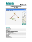
The table below shows a summary of the control pins used in un-buffered transparent mode.
Mode
IDLE
RX
RXEN
High
Low
TXEN
High
High
Note
As soon as preamble and SOF is
detected, the module sends data on
SDA and SCL.
TX
High
Low
As soon as preamble and SOF is
transmitted, the module start data clock
on SCL and read data on SDA
SLEEP
Low
Low
(Apply also in buffered mode when no
HW handshake is used)
CRC and addressing must be turn off using the un-buffered transparent mode.
2005 Radiocrafts AS
RC232™ User Manual (rev. 1.4)
Page 4 of 12
RC232™
Module Configuration
The configuration of the module can be changed in-circuit from the host during operation, at
the time of installation of the equipment, at the manufacturing test, or even as a stand alone
module. The configuration is changed sending commands on the UART interface after the
CONFIG pin has been asserted (low).
Once the CONFIG pin is activated the module enters command mode. The module will then
respond by sending a ‘>’ prompt on the TXD pin. This indicates that the module is ready to
receive commands. The CONFIG pin can then be de-asserted. Note that the CONFIG pin
must be de-asserted before the Exit command (‘X’) is sent to the module in order to return to
normal operation.
An exception for de-asserting CONFIG is when using ‘Z’ to enter SLEEP mode. In this case
the CONFIG pin should not be de-asserted but kept low until the module should exit SLEEP
mode as de-asserting the CONFIG line wakes the module again. The module will enter
normal IDLE mode after exiting SLEEP mode. No ‘X’ command is then necessary.
After a command is executed, the module responds with the ‘>’ prompt character again
indicating it is ready for a new command. Do not send a new command before the ‘>’ prompt
is received. The time required to execute a command can vary depending on the command
(see the Timing Information section). There is no ‘>’ prompt after the ‘X’ exit command.
The parameters that are set by commands directly take immediate effect after returning to
normal operation (IDLE), but will not be stored in non-volatile memory, and will be lost in case
the supply power is turned off or if the module is reset. These parameters are for example the
radio channel and output power.
Permanent changes of parameters can be done by writing to the configuration memory using
the memory command ‘M’. These are for example default radio channel, default output power,
UART handshaking, address mode and CRC mode, see the Configuration Memory section.
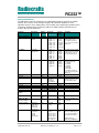
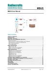
A list of commands is shown in the table below. Commands must be sent as ASCII characters
or their corresponding binary value. All arguments must be sent as binary values to the
module (not as ASCII representation for hex or decimal).
Parameter
Channel
Output power
Signal
Strength
(RSSI)
Destination
address
Memory
configuration
2005 Radiocrafts AS
Command Argument in hex (decimal)
‘C’ – 0x43 RC1040: 0x01-0x05 (1-5)
RC1080: 0x01-0x08 (1-8)
RC1090: 0x01-0x09 (1-9)
RC1240: 0x01-0x45 (1-69)
RC1250: 0x01-0x50 (1-80)
RC1280: 0x01-0x50 (1-80)
RC1290: 0x01-0x33 (1-51)
‘P’ – 0x50 0x01-0x05 (1-5)
‘S’ – 0x53
‘T’ – 0x54
RC12x0: return one byte
indicating the signal strength
RC10x0: No function
0x00 – 0xFF (0-255)
‘M’ – 0x4D (Address, Data): see list of
parameters below.
0xFF exits memory
configuration.
RC232™ User Manual (rev. 1.4)
Note
Data is stored in volatile
memory only. For variants
not listed here, refer to the
specific data sheet.
Data is stored in volatile
memory only.
Data is stored in volatile
memory only.
Used to enter memory
configuration menu.
Parameters changed are
stored in non-volatile
memory.
Page 5 of 12
RC232™
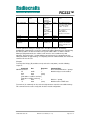
Exit command
‘X’ – 0x58
(none)
Sleep mode
‘Z’ – 0x5A
(none)
Test mode 0
‘0’ – 0x30
(none)
Test mode 1
‘1’ – 0x31
(none)
Test mode 2
‘2’ – 0x32
(none)
Exit to normal operation
mode. All changes of
parameters take effect.
CONFIG pin must be
asserted while in SLEEP
mode. Exit sleep mode by
releasing CONFIG pin.
List all configuration
memory parameters
TX carrier (lower FSK
frequency)
TX modulated signal
RC10x0: FSK square
wave
RC12x0: PN9 sequence
Test mode 1 must be used
before 2 can be used.
Return to Test mode 1
before exiting configuration
mode
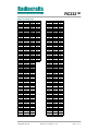
Note: ASCII characters are written as ‘X’, hexadecimal numbers are written like 0x00, and
decimal numbers are written like 10 throughout the text. A table of ASCII characters and their
respective hex and decimal values are found in the Appendix.
Any invalid command will be ignored and the ‘>’ prompt will be re-sent.
In order to use test mode 1 and 2, test mode 1 must always be set first. Modulation can then
be turned on using test command 2. The modulation must be turned off by using test mode 1
again before exiting the configuration mode (‘X’) in order to ensure proper operation in normal
mode.
Example:
To select RF channel 3, send the follow sequence after asserting the CONFIG line and the ‘>’
prompt is received:
Command
Hex
Response
CONFIG asserted
‘>’
‘C’
0x43
‘>’
3
0x03
‘>’
[A new command could be issued here]
‘X’
0x58
(none)
Comment/Note
De-assert CONFIG after ‘>’ prompt
Wait for ‘>’ prompt
Module returns to IDLE state
Note that the CONFIG line must be de-asserted after the first ‘>’ prompt was received, but
before the ‘X’ command.
2005 Radiocrafts AS
RC232™ User Manual (rev. 1.4)
Page 6 of 12
RC232™
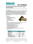
Configuration Memory
The table below shows the complete list of configurable parameters stored in non-volatile
memory. These values can be changed using the ‘M’ command. All addresses and
arguments must be sent as binary values to the module (not as ASCII representation for hex
or decimal). Argument range and factory settings for module variants not listed here are
shown in their specific data sheet.
Parameter
Description
Address
hex
Argument
dec
Factory
setting
hex (dec)
Comment
Default RF
channel
0x00
RC1040: 1-5
RC1080: 1-8
RC1090: 1-9
RC1240: 1-69
RC1250: 1-80
RC1280: 1-80
RC1290: 1-51
0x03 (3)
0x02 (2)
0x05 (5)
0x36 (54)
0x31 (49)
0x29 (41)
0x1A (26)
See data sheet for
channel frequencies.
For variants not listed
here, refer to the specific
data sheet.
RF_POWER
Default RF
output power
0x01
Default RF data 0x02
rate
0x05 (5)
0x05 (5)
0x05 (5)
0x05 (5)
0x05 (5)
0x05 (5)
0x04 (4)
0x05 (5)
0x03 (3)
0x02 (2)
0x03 (3)
0x03 (3)
See data sheet for output
power levels. For variants
not listed here, refer to
the specific data sheet.
RF_DATA_RATE
RC1040: 1-5
RC1080: 1-5
RC1090: 1-5
RC1240: 1-5
RC1250: 1-5
RC1280: 1-5
RC1290: 1-5
RC10x0: 1-5
RC1240: NA
RC1250: NA
RC1280: NA
RC1290: 3-5
Radio configuration
RF_CHANNEL
Reserved
Reserved
RSSI_MODE
RSSI mode
Reserved
Reserved
Reserved
Reserved
PREAMBLE_
LENGTH
SOF_CHARACTER
ABSOLUTE_MAX_
PACKET_LENGTH
PACKET_LENGTH
PACKET_TIMEOUT
2005 Radiocrafts AS
Max packet
length. When
buffer is full,
modem will
transmit data
Time before
modem timeout and
transmit
buffered data
0x03
0x04
0x05
RC10x0 only:
0:Disabled
1: Analogue
RSSI enabled
0x00 (0)
0x02 (2)
0x01 (1)
RC1240 and RC1280
have fixed data rate.
1: 1.2 kbit/s
2: 2.4 kbit/s
3: 4.8 kbit/s
4: 9.6 kbit/s
5: 19.2 kbit/s
For variants not listed
here, refer to the specific
data sheet.
RC12x0 does not have
analogue RSSI. Use the
‘S’ command instead.
0x06
0x07
0x08
0x09
Radio packet configuration
0x0A
4-8 bytes
0x64(100)
0x00 (0)
0x00 (0)
0x00 (0)
0x08 (8)
Do not set above 8.
0x0B0x0D
0x0E
0xD391D
A
0x80
(128)
Do not change.
0x0F
0x01-0x80
(1-128)
0x80
(128)
0x10
0x00-0xFE
(0-254)
0x00 (0): None
0x01 (1): 32 ms
0x02 (2): 48 ms
0x03 (3): 64 ms
0x7C (124): 2 s
0x7C
(124)
RC232™ User Manual (rev. 1.4)
Limited by hardware. Do
not change.
None means packet
timeout is disabled (not 0
s). Use packet length or
end character instead.
Timeout value is
(PACKET_TIMOEOUT x
Page 7 of 12
RC232™
0xF9 (249): 4 s
PACKET_END_
CHARACTER
Reserved
MAC_MODE
ADDRESS_MODE
0x11
0: None
0x00 (0)
0x0D (13): CR
0x0A (10): LF
0x5A (90): ‘Z’
Medium access, addressing and network management
0x12
0x02 (2)
0x13
0:Transparent
0x01 (1)
1: Buffered
0x14
0: No addressing 0x02 (2)
1: Reserved
2: Use
addressing
CRC_MODE
0x15
Reserved
Reserved
Reserved
UNIQUE_ID
0x16
0x17
0x18
0x19
SYSTEM_ID
Reserved
Reserved
Reserved
Reserved
Reserved
Reserved
DESTINATION_ID
Reserved
Reserved
Reserved
Reserved
Reserved
Reserved
BROADCAST_ADDR
ESS
Reserved
Reserved
Reserved
Reserved
Reserved
Reserved
Reserved
UART_BAUD_RATE
16 ms) + 0/16 ms
min/max
Unique ID
(UID)
System (net or
family) ID (SID)
Default
destination
address
Broadcast
address
0x1A
0x1B
0x1C
0x1D
0x1E
0x1F
0x20
0x21
0x22
0x23
0x24
0x24
0x26
0x27
0x28
0: None
2: CRC16
0-255
0x00-0xFF
(0-255)
0x00-0xFF
(0-255)
0x02 (2)
0x00 (0)
0x00 (0)
0x00 (0)
0x01 (1)
0xFE (254) is max, giving
4.080 sec.
Default is 2 s = 0x7C
(124)
ASCII character
Transparent means using
RXEN and TXEN.
Using addressing adds
SYSTEM_ID and
DESTINATION_ID to the
radio packet. Set to 0 in
transparent mode.
Set to 0 in transparent
mode.
0x01 (1)
0x0A (10)
0x0A (10)
0x0A (10)
0x0A (10)
0x01 (1)
0x01 (1)
0x01 (1)
0x01 (1)
0x00 (0)
0x00 (0)
0x00 (0)
0x00 (0)
0x04 (4)
0xFF
(255)
0x29
0x08 (8)
0x2A
0x00 (0)
0x2B
0x00 (0)
0x2C
0x00 (0)
0x2D
0x00 (0)
0x2E
0x00 (0)
0x2F
0x00 (0)
Data and configuration interface, UART Serial Port
Baud rate
0x30
RC12x0 only:
0x06 (6)
0x00: Not used
0x01: 600
0x02: 1200
0x03: 2400
0x04. 4800
0x05: 9600
0x06: 19200
Reserved
Reserved
Reserved
Reserved
0x31
0x32
0x33
0x34
0x08 (8)
0x00 (0)
0x01 (1)
0x05 (5)
2005 Radiocrafts AS
RC232™ User Manual (rev. 1.4)
Set to same as
BROADCAST_ADDRES
S when broadcasting.
All nodes accept
messages to this
address.
BE CAREFUL
IFCHANGING AS HOST
MAY LOOSE CONTACT
WITH MODULE!
Does not take effect until
module is re-booted /
reset.
RC10x0 UART baud rate
cannot be changed.
Page 8 of 12
RC232™
UART_FLOW_CTRL
UART flow
control
0x35
DATA_INTERFACE
Data interface
0x36
Reserved
Reserved
Reserved
Reserved
Exit from memory
configuration
0x37
0x38
0x39
0x3A
0xFF
0: None
0x00 (0)
1:CTS only
3:CTS/RTS
4:RXTX(RS485)
0x00: UART
0x00 (0)
using RXD and
TXD
0x01:
Synchronous
interface (SDA,
SCL) using
RXEN and TXEN
for direction
control
0x01 (1)
0x2B (43)
0x00 (0)
0x01 (1)
No argument
should be sent
Set to 0 in transparent
mode.
When buffered mode is
selected for MAC_MODE
use UART. For flow
control, see above.
When transparent mode
is selected for
MAC_MODE use
Synchronous interface.
To exit from command
mode the ‘X’ command
must be sent after ‘>’ is
received.
To make permanent changes to default values and other parameters, the Memory
Configuration command ‘M’ is used. This command should be followed by pairs of byte being
the memory address and the new value to be stored at that address. In order to exit the
Memory Configuration mode, the ‘address’ 0xFF must be sent, but without any data
argument. Then wait for the ‘>’ prompt while the internal memory is re-programmed (See
Timing Information for typical delay). To completely exit from command mode, the normal exit
command ‘X’ must be sent.
Example:
To change the Unique_ID (at address 0x19) and set it to 100 (0x64), send the following
sequence:
Command
Hex
Response
CONFIG asserted
‘>’
‘M’
0x4D
‘>’
0x19
0x19
(none)
100
0x64
(none)
[new address could be sent here]
[new value could be sent here]
0xFF
0xFF
‘>’
‘X’
0x58
(none)
Comment/Note
De-assert CONFIG after ‘>’ prompt
Module ready to receive address
Wait for ‘>’ prompt
Module returns to IDLE state
Test mode 0 (‘0’ command) can be used to list all parameters stored in non-volatile memory.
This command can be used to verify and check the module configuration.
2005 Radiocrafts AS
RC232™ User Manual (rev. 1.4)
Page 9 of 12
RC232™
Power Management
The module can be set in SLEEP mode or OFF mode in order to reduce the power
consumption.
The low power SLEEP mode is entered by using the SLEEP command, or by pulling both
RXEN and TXEN low. In SLEEP mode the module will not receive or detect incoming data,
neither from the host (UART port) nor from the RF transceiver. The module is awakened from
the SLEEP mode by a positive edge on the CONFIG, RXEN or TXEN pins.
Note: If UART handshake is used, the RXEN and TXEN pins can not be used to enter SLEEP
mode. In this case, use the SLEEP command.
The ultra-low power OFF mode is entered by pulling the ON/OFF pin low. The module will
then shut down completely. The module is turned on by setting the ON/OFF pin high (to
VCC). After the module has been in OFF mode all operational parameters are set to their
default values.
2005 Radiocrafts AS
RC232™ User Manual (rev. 1.4)
Page 10 of 12
RC232™
Appendix: ASCII Table
HEX
0
1
2
3
4
5
6
7
8
9
0A
0B
0C
0D
0E
0F
10
11
12
13
14
15
16
17
18
19
1A
1B
1C
1D
1E
1F
20
21
22
23
24
25
26
27
28
29
2A
2B
2C
DEC
0
1
2
3
4
5
6
7
8
9
10
11
12
13
14
15
16
17
18
19
20
21
22
23
24
25
26
27
28
29
30
31
32
33
34
35
36
37
38
39
40
41
42
43
44
CHR
NUL
SOH
STX
ETX
EOT
ENQ
ACK
BEL
BS
HT
LF
VT
FF
CR
SO
SI
DLE
DC1
DC2
DC3
DC4
NAK
SYN
ETB
CAN
EM
SUB
ESC
FS
GS
RS
US
SP
!
"
#
$
%
&
'
(
)
*
+
,
2D
2E
2F
30
31
32
33
34
35
36
37
38
39
3A
3B
3C
3D
45
46
47
48
49
50
51
52
53
54
55
56
57
58
59
60
61
HEX
40
41
42
43
44
45
46
47
48
49
4A
4B
4C
4D
4E
4F
50
51
52
53
54
55
56
57
58
59
5A
5B
5C
5D
5E
5F
60
61
62
63
64
65
66
67
68
69
6A
6B
6C
DEC
64
65
66
67
68
69
70
71
72
73
74
75
76
77
78
79
80
81
82
83
84
85
86
87
88
89
90
91
92
93
94
95
96
97
98
99
100
101
102
103
104
105
106
107
108
CHR
@
A
B
C
D
E
F
G
H
I
J
K
L
M
N
O
P
Q
R
S
T
U
V
W
X
Y
Z
[
\
]
^
_
`
a
b
c
d
e
f
g
h
i
j
k
l
.
/
0
1
2
3
4
5
6
7
8
9
:
;
<
=
6D
6E
6F
70
71
72
73
74
75
76
77
78
79
7A
7B
7C
7D
109
110
111
112
113
114
115
116
117
118
119
120
121
122
123
124
125
m
n
o
p
q
r
s
t
u
v
w
x
y
z
{
|
}
−
CTRL
^@
^A
^B
^C
^D
^E
^F
^G
^H
^I
^J
^K
^L
^M
^N
^O
^P
^Q
^R
^S
^T
^U
^V
^W
^X
^Y
^Z
3E
62
>
7E
126
~
3F
63
?
7F
127
DEL
2005 Radiocrafts AS
RC232™ User Manual (rev. 1.4)
Page 11 of 12
RC232™
Document Revision History
Document Revision
1.0
1.1
1.2
1.3
1.4
Changes
First release
Configuration memory addresses corrected
Revision 1.2 apply for modules marked E.S. (Engineering Sample)
Data buffer length changed from 200 to 128
Test commands added in Module Configuration
ASCII table added in Appendix
Minor corrections and editorial changes for clarity
Revision 1.3 apply for all modules revision 2.0 and onwards
Corrected PACKET_TIMEOUT default value to 0x7C
Changed ADDRESS_MODE value from 1 to 2 when using addressing
Added note on Test mode 2, that Test mode 1 must be used first, and also
before exiting configuration mode
Included UART baud rate settings for RC12x0
Clarifications on un-buffered transparent mode added
Added data for RC1250
Updated factory setting values in configuration memory table
Disclaimer
Radiocrafts AS believes the information contained herein is correct and accurate at the time of this printing. However,
Radiocrafts AS reserves the right to make changes to this product without notice. Radiocrafts AS does not assume
any responsibility for the use of the described product; neither does it convey any license under its patent rights, or
the rights of others. The latest updates are available at the Radiocrafts website or by contacting Radiocrafts directly.
As far as possible, major changes of product specifications and functionality, will be stated in product specific Errata
Notes published at the Radiocrafts website. Customers are encouraged to check regularly for the most recent
updates on products and support tools.
Trademarks
RC232™ is a trademark of Radiocrafts AS. RC232 is a proprietary protocol for serial communication between a host
and an RF module.
All other trademarks, registered trademarks and product names are the sole property of their respective owners.
Life Support Policy
This Radiocrafts product is not designed for use in life support appliances, devices, or other systems where
malfunction can reasonably be expected to result in significant personal injury to the user, or as a critical component
in any life support device or system whose failure to perform can be reasonably expected to cause the failure of the
life support device or system, or to affect its safety or effectiveness. Radiocrafts AS customers using or selling these
products for use in such applications do so at their own risk and agree to fully indemnify Radiocrafts AS for any
damages resulting from any improper use or sale.
© 2005, Radiocrafts AS. All rights reserved.
Contact Information
Web site: www.radiocrafts.com
Email: radiocrafts@radiocrafts.com
Address:
Radiocrafts AS
Gunnar Schjelderups vei 11
NO-0485 OSLO
NORWAY
Tel: +47 970 86 676
Fax: +47 22 71 29 15
E-mail: sales@radiocrafts.com
2005 Radiocrafts AS
RC232™ User Manual (rev. 1.4)
Page 12 of 12