1
THE ACCELERATOR 286
THE ACCELERATOR 286
User's Manual
The Accelerator 286 is an internal option card designed to
significantly enhance the performance of your iBM PC,
PC/ XT, or compatible computer. The Accelerator 286 deIivers faster performance than an I BM AT in computation
intensive operations at a very reasonable cost.
The Accelerator 286 replaces your computer's 8088 microprocessor with an 80286 16-bit microprocessor (the same
microprocessor used in the I BM AT and AT compatibles).
The 80286 processor runs at a full 8 megahertz (MHz), as
compared to the 8088's clock speed of 4.77 MHz. The
Accelerator 286 also includes 8 kilobytes (K) of cache memory. Software applications can run up to seven times faster
with the Accelerator 286. The Accelerator 286 is not known
to be incompatible with any software or any I BM PC, XT
orcompatible system.
Your Accelerator 286 has several important featu~es which
ensure high performance and full compatibility.
-
80286 microprocessor
Fast clock speed of a full 8 MHz
8K bytes of high speed zero-wait-state cache memory
Support for 80287 running at 5 or 8 MHz
Hardware switchable 8088 remains in system for fu II compatibility
- Automatic cache-disable during self-test for compatibility
with most BIOSes
- Hardware switchable cache-disable
-1-
These features and more are explained in this manual. You
should read the entire manual before you begin to install
your Accelerator 286. I n addition, if you have never installed option cards in your computer, refer to your computer's manual before proceeding.
INST ALLATION
Your Accelerator 286 is very easy to install. All you need is
the card itself \\lith attached ribbon cable, an IC chip puller
and a sorewdriver.
ABOUT CACHE MEMORY
Cache memory consists of 8K bytes of random-access memory (RAM) on the Accelerator 286's 16-bit bus. This memory allows the Accelerator 286 to utilize the full potential
of its 80286 microprocessor. Unlike the 8088, which is installed on an 8-bit bus and can access only one byte of memory at one time, the 80286 is a true 16-bit microprocessor
installed on a 16-bit bus. This cache memory provides the
80286 with memory (for program instructions and data) that
it can access at high speed with zero-wait-states one word
(two bytes) at a time.
To insure full compatibility with a wide range of machines
clild system BIOSes, the Accelerator 286 cache memory is
dutomatically disabled during the machine's self test. For the
li/st two minutes after re-booting or switching to the 80286
using the toggle switch, you will not see a marked increase
lrom the PC's "normal" speed. After this initial 2 minutes,
high spcL'l1 caching will begin.
Important: Do not remove the ribbon cable from the Accelerator 286. If for any reason you do remove the cable,
first mark the Pin 1 end of the cable connector to ensure that
you insert the cable connector correctly when you re-install
the cable.
~
INITIAL STEPS
Turn the computer off and disconnect the power cord first
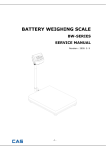
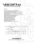
from the wall outlet and then from 'the back of your computer, Remove the cover from the top of your system. The
cover of the I BM PC and IBM PC-XT is secured by five
screws in the back of the system (see the diagram-Removing
the Cover). Some compatibles have different scn~w configurations or flip top covers (refer to the owners manual for
your mac~ine). Remove and retain the screws as they will be
needed to close the back of the set after installation. Once
the screws are removed, carefully slide the cover toward the
front of the system to remove it.
The Accelerator 286 should go into the full length expansion
slot closest to the 8088 socket on the motherboard. The
connector ribbon cable length will govern which expansion
slot can be used. Remove the retaining screw ard dummy
metal adaptor bracket from the back of the computer for the
-2-
-3-
must remove it whether or not you intend to install a 80287
math coprocessor on the Accelerator 286. Use the Ie extractor to remove the 8087 following the same steps as lemoving
the 8088.
If you will be using an 80287 math copmcessor chip, read
the section entitled Using The 80287 with Your Accc'bator
286 following these installation instructions.
Otherwise,
continue to the next section.
t'
..&--- R. t ..
S.-:
1. 11 1 f'\ (]
t"
ew
~
REMOVING THE COVER
/
Br-acke
appropriate expansion slot (see the diagram - Removing
the Adaptor Bracket). Be sure to save the screw as it will be
needed tQ fasten the Accelerator 286.
Remove the 8088 from your computer's "motherboard" and
set it aside to be reinstalled on the Accelerator 286 card. Use
an Ie extractor or small screwdriver to pry first one end and
then the other end of the 8088 chip loose. Do not pry the
8088 up at too much of an angle and take care not to bend
any pins.
REMOVING
Remove the 8087 if it is installed in your motherboard. The
8087, if present, is normally located immediately to the right
of the 8088 chip that you removed. If you have a 8087, you
-4-
THE
ADAPTOH
D~~~
REINSTALLING THE 8088
Your Accelerator 286 offers the unique and valuable feature
of allowing you to keep the 8088 on the Accelerator 286
board for full compatibility with speed dependent programs which cannot run at the high speed of your Accelerator 286. To run these programs, toggle the upper switch
"down" for PC speed 8088 mode. For more information
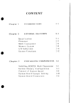
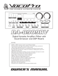
about the use of the 8088 switch, see the section entitled Switches. The 8088 should be installed into the socket labeled U8 on your Accelerator 286. The 8088 socket is located one row below the 40 pin ribbon cable, just below
and to the left of the top switch (see the diagram - Accelerator 286 Layout). When installing the 8088 match the dot or
notch on one end of the 8088 with the notch on the left side
of the socket of the Accelerator 286 (assuming you are
looking at the Accelerator 286 as shown in diagram - Accelerator 286 Layout). The 8088 must be pointed in the
correct direction or you could destroy the 8088 processor
·and damage your Accelerator 286. Make sure all of the pins
are lined up with their corresponding holes in the socket and
press down gently but firmly using a slight rocking motion,
being careful not to bend any pins. If any pins are bent,
remove the 8088 and gently straighten them because the pi ns
can only be flexed a few times before breaking.
ACCELERATOR
LAYOUT
511HZ ERR NH I
~(il)
'."1
..11
c::=:=:J1
I
"--;1 Of~
~ ~O
0
,,------,I >
.;----,:
.;---'1
o Eo
L=-:J
f
0c=J
..1+
i1J W
•• MHZ
..12
~
@
PC
J7
XT
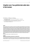
CONFIGURING THE ACCELERATOR 286 CARD
Next, set jumper J7 located at the lower left hand side of the
card in the "up" position if your computer is an I BM PC or
PC compatible or in the "down" position if your computer is
an IBM XT or XT compatible (see the diagram-Setting
-6-
286
;-- .
~;
I
C-- - - ,
-=
Up
0
_
80Z"
Turbo
c::::::==J
-->- - - ,
l
O(
> ""- I
8088
I
so~
0> I L==-::J 0
0~>_~I ----,I 0
<-.>- - - - - '
L->
----'I ~J
<->
< - - >- - - - - '
<->----' o
\:.
Down
_
C~ch.
oi
• a.b 1.
l
.
the PC-XT Selector Jumper). This jumper consists of 3 pins
::tnd 1 jumpcr clip. For insturctions on setting these jumpers,
see the section entitled Jumper Settings.
SETTING THE PC-XT
SELECTOR JUMPER
1I
,
For XT
Installation
For PC
Installation
There are 2 switches located on the back plate of your
Accelerator 286. These switches are used to ensure full compatibility with all software and system BIOSes. For rull
Turbo operation, both the upper and the lower switches
should be set in the "up" position. (More information about
the functions of these switches is provided in the section entitled Switches.) For installing the Accelerator 286, put both
switches in the "up" position now (see the diagram-Accclerator 286 Lrlvout).
PC
PC
~•
•
~
J7
J7
XT
XT
INSERTING THE ACCELERATOR 286
The libbon cable should arrive from the factory connected
to the cable connector of your Accelelatol 2k6. II it is not
connected, it should be connected to the 40 pin cable COIlnector on the Accelerator 2k6 so that there is nol a twi<,\ in
t he cable aftcr the other end i<; installed in the 80RR ,>ockel,
Inserl the other end of Accc1erator 286 ribbon Cclble COnll('CtOi int() 1 he l'lllpt y 808k socket. Make Sli Il' that t he pin~
nldtch up ('xdctly 10 the hoics in the ~ockct which ihc gOSi-;
(dille'
froill.
(,)I-(f \v:lil 111~"
Do nol
\.
lWI<,1
(";(l["(1i()r
Ihe ribboll C(lbk ,Ind do not
2~()'s 111!)llf1t
:~ f'\!~I\.-k(;l
ill,,'!t
jl",",i,-(l
!.!~';.'
rear of the system unit as shown in the diagram - Inserting
the Accelerator 286. Using two hands, grasp each end of
the card and, using even pressure, push the card's gold-finger
connectors straight down into the expansion slot. Be sure
that you have inserted the card completely and securely into
the slot. Then secure the mounting bracket with the screw
Make sure that the air flow
from the dummy bracket.
through lhe computer is unrestricted to permit proper cooling of the Accelerator 286. Replace the system unit cover
and reconnect the power cord.
OPERATION
The Accelerator 286 is now installed and you are ready to
run your I BM PC, PCjXT or compatible computer at AT
speeds. Turn on your computer and run any program to
verify that your Accelerator 286 is functioning correctly. If
you have installed an 80287, run any program that uses it to
verify that the 80287 is also running correctly. If you have
any pmblems, see the section entitled Tmuble Shooting in
this manual.
The Accelerator 286 does not need software or special proceoperate. With Ihe Accelerator 286 installed, your
syslcl1l will worh. just Ihe way it did before, only fastel.
cJUI'CS 10
USING THE 80287 WITH YOUR ACCELERATOR 286
4- Rear
INSERTINC THE ACCELERATOR 216
-10-
Pan.l
rhe i-\02K7 is ,I "Illath coprocessor" that speeds up many
flodtillg point opcl<ltions. The following steps will enable
you to illSLlil <Ill i-\0287 math coprocessor on your Accelerator 286.
Insert the i-\()2K7 inlo the socket provided for it (U10) on
your !\clcll'l,llm 2K(,. Pin I of the 80287 is identified by a
SI11,,1/ circle Oil Ihe [lMk of the chip. When you insert the
80287 chip into Ihl' SIll kcl, place Pin 1 at he lower left
corner. 1 he ~lll,lIl notch "t t hl' Pin 1 end of the chip corresponds to " notlh "t thl' Icit ~ilk of the socket. Usc these
identifying Ill.llks to 111""(' '>lIll' you insert the chip correctly.
Carefully ,iligll ,11/ of the chip's pins with thl socket hoil-s,
and then prcss till' chip gcnth into pl,lcc, lIsing d slight
roch.ing Illotion if IlL'Cl'SS,lIY. Ik l'\tll'flH'ly (Mellil l]f)t to
II
bend any of the pins, as this could damage or destroy your
80287. See the section entitled Reinstalling the 8088 for
more detailed instructions on physically installing the 80287.
Your Accelerator 286 can run with either a 5 or 8 MHz
80287 math coprocessor. You must set the 80287 jumper to
correspond to the speed of the coprocessor you arc using. A
5 MHz 80287 is usually marked 80287 or 80287-3 and an 8
MHz 80287 is usually marked 80287-8. For instructions on
how to set a jumper, refer to the section entitled Jumpers
Settings.
The Accelerator 286 is compatible with all 3 commonly used
numeric processor error handling system:
Non Maskablc
Interrupts (NMI), Numeric Processor Error (ERR), and sof(A numeric processor clror i~
tware handling of errors.
caused by "illegal" activities such as dividing by lero.) Most
software for the AT llses NMI. You should initi,dly <;ct JI t()
the right tor NMI. If this creates "Parity Errol" or "P~lrity
Check" messages to ,lprX'dr on your scrcen when lI\ing till'
80287, ~witch the jumper to the lett for ERR. "Y(lll COIltinue to h.tvl' probkllls, \lIch ciS phantom chdr,lctel~ "Ppl\l!"..,
on the SUl'l'll while lhillg the 80287, set J loll
For 8 MHI 80287:
For 5 MHz 80287:
Set J2 - OFF
Set j3 - ON
Set J5 - ON
Set j2 - ON
SIIIINC, 1111 80287 NUMERIC
I RROR HANDLING JUMPER
PI~(}(I SSOR
Set J3
OFF
SetjS ·OFF
ERR
<"'l,ttill.~
I
(II
NMI
I·~I
SETTI NG TH E 80287
SPEED JUMPERS
Jif.
'
....
~
J1
For 8 MHI Opl'ldtiorl
For 5 Mhl Operation
-]
511H"
:.
•
8MH:z
c'--r== .
r.-+·-e]
J3
[
-I
FRR
')('IIIII,~
J4
,
,I-
•
lUi LRR
J2
IE::!:] • I
I J3
J
lsMH",
ERR
i1111lPI'1
'{l
__ I
I
NMI
~-. ~
Set "Off"
5MI-k
~ [C!~
NMI
-,
'.
•i I
L.:--~BMfk.
J2
NMI
.~
--13-
SWITCHES
80286-8088 Switch - In Turbo mode, tl-]e Accelerator 286
runs with the 80286 microprocessor operating at a full 8
MHz. However, there are a few application software programs that are speed dependent and will not work with the
microprocessor running at 8 MHz. These software packages
can not ru n at the 8 MHz high speed of the 80286 in you r
Accelerator 286. (These programs cannot run on the IBM
PC-AT or AT compatibles for the same reason.) To insure
full compatibility with all application software, your Accelerator 286 has a toggle switch located in the back plate
attached to the card. (It is the upper switch and is located
on the outside rear of your PC after installation.) To run
I
these speed dependent programs, tum off the power, toggle
the switch down, turn on the power, and your PC will reboot
in the slow speed mode (4.77 MHz with the 8088 operating).
To return to the high speed 80286 mode, there is no need to
turn off the power, just toggl y the switch up and your
Accelerator 286 will automatically reboot to the 80286 and
run at a full 8MHz.
•
order to ensure compatibility.
For example, while the
Accelerator 286 is fully compatible with Lotus-Intel-Microsoft (LIM) Extended Memory Specification (EMS) for
accessing more than 640K of memory, some non-standard
extended memory systems may cOlllliet with the cache
memory. Similal'ly, some low level h.lrd disk fOlmatting,
(whieh is llslJally performed by till' 1Il.l11UI,lclLllcr before
shipment) <llld sorne older, floppy disk bdscd copy protection
scllerncs uo not pcrmit etchillg. In audition, if you run a
d iagnost ic progr,llli to check your system's memory, you
should di'>,lbk cache memory to give the diagnostic program
dilect access to the system's main memory. In these situat ion'>, you Clll dis,lble cache by using the toggle switch which
is the lower switch on the outside rear of your PC after
inst.llidtioll. I Ill' uche disable switch can be used to turn
cache ()Il or off while operating without rebooting or having
to S,lve your dJta. Please note that it takes approximately 2
minutes ,titer you have toggled the switch "up" for cache to
tum on.
JUMPER SETTINGS
Cache Disable Switch - With cache enabled (SW2 "Up")' the
Accelerator 286 runs programs in its cache memory for
highest performance. There are, however, some situations in
which you would not want the high speed cache to operate in
To ''set'' a jumper refers to the pins that are inserted into and
covcred by the plastic jumper clip. For example to set a 2
pin jumper (eg J2), the jumper clip should con,lect the two
pins. For a 3 pin jumper (eg J 1), setting a jumper to the
Icrt IlleJns that you cover the left 2 pins and leave the rightmost pill exposed and setting a jumper to the right means
that you cover the right 2 pins and leave the leftmost pin
exposed. To turn a jumper "off" is to cover only one pin of
the 2 (or 3) pins in the jumper group and leave the other pins
exposed. This has the same effect as completely removing
-14-
-15-
I MPORT ANT NOTE: Whenever toggling between the 8088
and 80286 microprocessors, you must first save all data as
the switch between microprocessors will reboot the computer and all unsaved data will be lost.
I
,
the jumper clip but prevents losing the clip in case it is ever
needed in the future.
TECHNICAL SPECIFICATIONS
Microprocessor
For 80287 operation- set jumper to the left for ERR
(Numeric Processor Error) and to the right for NMI (Non
Maskable I nterrupt). If no 80287 is installed, the jumper can
be in any position.
J1 -
J2 -
For 80287 operation- Must be installed to run the
80287 at 8 MH/. Must be "off" to run the 80287 at 5 MHz.
If no 80287 is inqdllcd, the jumper can be in any position.
80286-8 running at 8 Mill
80287 Math Coprocessor Compatibility
;\cc()rnlll()d,rtl'~ ()pti()ll,ll ') MHI 80287-3 (running at 5 MHz)
or 8 Mill S0287 or S0287-8 (running at 8 MHz).
8088 Switchabk
J3
For 80287 or)l'ration
Must be installed to run the
80287 at ') M~ I/. Must be "off" to run the 80287 at 8 MHz.
If no 8(21)7 is installed, the jumper can be in any position.
!OIC()rllp.llihility with timing dependent programs.
Acccss Methods
J4 - For manufacturing test purposes only.
J5 - For 80287 operation- Must be installed to run the
80287 at 5 MHz. Must be "off" to run the 80287 at 8 MHz.
If no 80287 is installed, the jumper can be in any position.
;\Cll"""'l'~ ~ystl'm memory and performs system I/O operations
by S()SS eillulation through a ribbon cable to the 8088
socket ()rl lile main circuit board.
Cache
J6
- For manufacturing test purposes only.
8K bylL''> 01 ICIO-wait-state memory on the board.
j7 - For IBM PC or PC compatible, must be set in the up
position. For IBM PC-XT or XT compatible, must be set in
lile down position.
J
8
lor rn,lIlufacturing test purposes only.
Ifl
Cache Dis,lblc Switch
For I()w level IldVl' disk formatting, memory diagnostic testing, and 11I1i cO/llp,ltibility with all copy protection and
expanded I1lCl1l()IY.
-17--
DMA Compatibility
Fully DMA compatible
Dimensions
5 inches x 9 inches
-18-
J