1
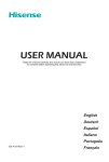
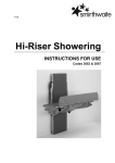
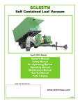
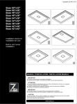
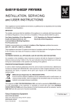
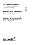
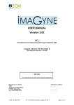
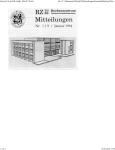
S250/S350-CL
ENERGIZER (HP)
ARCSPRAY POWER SUPPLY
USER MANUAL
PLEASE READ THIS MANUAL CAREFULLY
BEFORE USE
Metallisation Ltd
Equipment Manual Amendment Register
Issue
No
1
Date
20/03/12 New Manual
Description Of Modifications
Section(s)
Amended By
Amended
N/A
R Campbell
Before using the Equipment, read and understand this
operating manual. In particular, refer to the Safety
Precautions detailed in Section 2.
Under NO circumstances should any modifications be
made to the equipment without prior written approval from
Metallisation
CONTENTS
SECTION
1
THE ENERGIZER
1.1
Description
1.2
Features
1.3
Specifications
SECTION
2
SECTION
5
Maintenance and Repair
5.1
Routine Maintenance
5.2.1 Fuses
5.2.2 Diodes
5.2.3 Thermal Switch
5.2.4 Over Current Protection
5.2.5 Pressure Switch
SAFETY PRECAUTIONS
SECTION
SECTION
PREPARING THE ENERGIZER
3.1
Preliminary Check List
3.2
Handling Instructions
3.3
Connecting the Power Supply
3.4
Connecting the Air Supply
3.5
Attaching the Pistol
3.6
Loading the Wire from Mig Reels
3.7
Loading the Wire from Drums
SECTION
6
3
4
OPERATING THE ENERGIZER
4.1
Starting to Spray
4.2
Shutting Down
FAULT FINDING
6.1
No Nozzle Air
6.2
Air but No Voltage
6.3
Insufficient Voltage
6.4
Fan Stops
SECTION
7
Useful Information
7.1
7.2
7.3
7.4
Recommended Spares Holding
Spares List
Circuit Diagrams
Pneumatic Diagram
SECTION
THE ENERGIZER
1.1
1.2
1.3
Description
Features
Specifications
1
1.
THE ENERGIZER S350
1.1 The Metallisation Energizer S250/S350
is an ergonomically designed Electric Arc
Spraying Supply and Control Systems.
It has been specially designed specifically
for metal spraying and its benefits will be felt
when used in conjunction with the full range
of Metallisation Pistols.
This single unit houses the electric and
pneumatic controls for the system and can
carry a removable wire dispensing system
for all systems (optional) which is covered to
protect against dust.
1.2
Features
1.2.1 The continuously variable spraying
current is controlled by the motor speed
control potentiometer to the drive motor.
The spray current of the system is a guide
to the material throughput and is infinitely
variable up to its full nominal rating at 100%
duty cycle i.e. 250A or 350A. The spray current can now be set, via a closed loop
control, to a pre-defined value via the control pot.
1.2.2
The 3 phase Power Transformer and Variable Inductance Choke are designed to
provide optimum arc characteristics and stability for any currently specified arc
sprayed coating.
1.2.3
The 3 phase Switched Voltage Control gives finely stepped control over voltage and
provides for reliable control under arduous conditions. This feature allows selection
of the spraying voltage for all material or material combinations maintaining coating
quality with the most robust circuitry.
1.2.4
The Atomising Airflow to the pistol spray head is continuously variable allowing
control over the coating texture and the coating structure.
1.2.5
The purpose built Wire Dispensing System ensures that the wire follows the optimum
line to the pistol and reduces dust contamination of the wire
1.2.6
As protection for both the equipment and the operator, electrical, thermal and air
pressure cut-outs are provided.
1.2.7
Full Fan Assisted Cooling is provided for the transformers and rectifier.
1.2.8
System displays provide easy monitoring of the equipment.
1.2.9
A current sensor is fitted to the unit which limits the spray current to the maximum
rated for the unit, i.e. 250A or 350A.
1.2.10 Two fixed and two braked castor wheels are provided which ease handling and
improve the units mobility.
1.2.11 All the supplies from the Energizer to the spraying pistol e.g. power cables, air hoses,
control cables etc. are all quick release fittings and issue near ground level as an aid
to pistol handling.
1.3
SPECIFICATIONS S250/S350 ENERGIZER
1.3.1
OUTPUT CHARACTERISTICS
Spraying Current S250 :
Spraying Current S350 :
0-250A @ 100% Duty Cycle
0-350A @ 100% Duty Cycle
Voltage :
0-50V dc (nominal)
Atomising Air:
1.56³/min @5 bar (55cfm @ 90 psi)
1.3.2
INPUT REQUIREMENTS
1.3.2.1 Electricity:
S250CL 380/415 VAC 3 Phase + Earth 50/60hz
S350 CL 380/415/460 VAC 3 + Earth Phase 50/60hz
S250 CL 200/220V 3 phase + Earth 50/60hz
S350 CL 200/220 VAC Phase + Earth 50/60hz
NOTE:
The S250 Energizer for 380/415/460V input must be connected to a suitable isolator or
switched socket protected by a suitable protective device rated at 20amps/ph
The S250 Energizer for 200/220VAC input must be connected to a suitable isolator or
switched socket protected by a suitable protective device rated at 45/40amps/ph
The S350 Energizer for 380/415/460VAC input must be connected to a suitable isolator or
switched socket protected by a suitable protective device rated at 32amps/ph
The S350 Energizer for 200/220VAC input must be connected to a suitable isolator or
switched socket protected by a suitable protective device rated at 60/55amps/ph
THIS EQUIPMENT MUST BE CONNECTED TO EARTH.
1.3.2.2 Clean Dry Compressed Air Min:1.3.3
1.56m³/min @6 bar (55cfm @ 90 psi)
DISPLAYS
Current:-
0-400 Amp analogue
Voltage:-
0-50 Volts analogue
Atomising and Aux Air:
0-140psi (0-10 bar) analogue
Mains Indicator:
Red Neon Indicator
1.3.4
GENERAL
1.3.4.1 Dimensions S250/S350:
Width (Inc Wheels):
Length:
Height (Inc Handle):
680mm
900mm
913mm
1.3.4.2 Weight (Inc. optional drive
unit and wire dispenser)
S250: 200Kg / S350: 238Kg
1.3.4.3 Power Rating:
S250: 12KVA / S350: 16KVA
1.3.4.4 Power Factor:
0.85 Lag
1.3.4.5 Auxiliary Circuits:
110Vac and 24Vdc
1.3.4.6 Pressure Switch Setting:
30 psi (2.0 bar)
1.3.4.7 Tropicalisation:
Standard
SECTION 2
SAFETY PRECATIONS
2
SAFETY PRECAUTIONS
This section outlining “Safety Precautions” has not been included because of any great
dangers inherent in metal spraying operations, but like most industrial processes,
malpractices and careless procedures can create hazards for personnel and damage
equipment.
2.1
The mains supplies MUST be disconnected before removing any of the outer panels.
This can be achieved as follows:a)
Switch off the power at the supply point and remove the mains supply plug.
b)
Remove the fuses from each phase at the isolator or distribution board.
2.2
ALL maintenance or overhaul should be conducted by a fully qualified electrician.
2.3
NEVER spray onto hoses, cables or instruments.
SECTION 3
PREPARING THE ENERGIZER
3.1
3.2
3.3
3.4
3.5
3.6
3.7
3.8
Preliminary Check List
Handling Instructions
Connecting the Power Supply
Connecting the Air Supply
Attaching the Pistol
Loading the Wire
Loading the Wire from Drums
Optional Power Extension Trolley for the DUAEV
3.1
PRELIMINARY CHECK LIST
3.1.1
Remove any packing materials and ensure that the equipment has suffered no
damage whilst in transit (See Conditions of Sale).
3.1.2
Check that the following items are available:a)
b)
c)
d)
1 off
1 off
1 off
1 off
-
Energizer
Wire Dispenser (if ordered as option)
Connection for ¾” bore air hose
Operating Manual
3.2
HANDLING INSTRUCTIONS
3.2.1
The Energizer must only be lifted from the base, under no circumstances should it be
lifted by the handle or by the M12 thread that locates the dispenser spigot
3.2.2
Care must be taken if attempting to transport the Energizer by fork lift truck not to
damage the underside of the unit
3.3
CONNECTING THE POWER SUPPLY
3.3.1
The Energizer should be connected a suitable power supply as defined in the
specifications by a qualified electrician.
3.3.2
Position the Energizer in the area in which it is to be used taking in to consideration
the environment in which it will be operated.
3.3.3
If it is intended that the Energizer be available to several locations, use suitable
outlets in each area in preference to long trailing cables.
.
3.3.4
If fitted remove the wire dispenser and drive unit from the top of the energizer.
Remove the top rear panel from the energizer and attach the power cable to
terminals 1, 2, 3 and the Earth.
Check that the input voltage is correct for the unit, the voltage selector terminals (A) can be
found beneath the top front panel, see power circuit EN210. Note: Terminals shown below
are dependent on the unit supplied.
Figure 3.1 200/220VAC System
Figure 3.2 380/415/460VAC System
A
3.3.5
After connection, switch on the Energizer at the “Off/On” switch.
Check that cooling air is being blown from the rear panel. The fan motor is a threephase motor and is therefore phase dependant, if it is blowing air through the front of
the unit, isolate the system, rotate two phases and retry.
3.3.6
Turn the unit off and refit all panels and the wire dispenser/drive unit if fitted.
3.4
CONNECTING THE AIR SUPPLY
3.4.1
The Energizer should be connected to a mains air supply outlet by a length of ¾”
bore air hose.
It is strongly recommended that a filter unit be installed at the mains outlet point
A capacity of 55cfm @ 90psi (1.56m³/min @ 6 bar) is usually adequate. Check the
appropriate pistol manual if in doubt.
3.5
ATTACHING THE PISTOL
3.5.1
Switch off the Energizer at the mains.
3.5.2
Take the Arcspray pistol and ensure that the power cables, supply hoses and the
control cable are attached to the pistol in accordance with the instructions given in the
relevant pistol operating manual.
3.5.3
Connect the power cables to the DINSE quick release sockets at the bottom front of
the Energizer. Polarity is not important.
3.5.4
Connect the pistol nozzle hose to the outlet marked “NOZZLE”
3.5.5
Plug the pistol control lead into the socket marked “CONTROL”
3.5.6
Plug the drive control lead into the socket marked “DRIVE”
3.6
LOADING THE WIRE FROM THE MIG REELS
3.6.1
Remove Mig Reel from its packaging.
3.6.2
Load reel on to dispenser so that the wire feeds from the bottom of the reel.
3.6.3
Open the drive pinch rollers by moving the lever forward.
3.6.4
Straighten approximately 200mm of wire and feed through the DUAEV unit 25mm
protrudes. Attach a strip of rag to each wire and apply 2-3ml of wire oil to each.
3.6.5
When both wires are protruding close the drive pinch rollers by moving the lever
backwards.
3.6.6
Connect the wire conduits to the DUAEV ensuring they are locked in place.
Figure 3.1 Mig Reel Dispenser and DUAEV drive unit Fig 3.2 Position of rag strip for wire oil
3.7
LOADING THE WIRE FROM DRUMS
3.7.1
Position wire drums so that they are approximately 50mm apart.
IT IS IMPORTANT THAT THEY DO NOT TOUCH EACH OTHER AS THIS CAN
CAUSE A SHORT CIRCUIT.
3.7.2
Remove the lid of the drum and locate the end of the wire.
3.7.3
Feed wire through the top of the dispenser cone.
3.7.4
Secure the dispenser cone to the drum using the locking screws.
3.7.5.
Feed the wire through the Teflon tube until it protrudes 300mm.
3.7.6
Open the drive pinch rollers by moving the lever forward.
3.7.7
Straighten approximately 200mm of wire and feed through the DUAEV unit 25mm
protrudes. Attach a strip of rag to each wire and apply 2-3ml of wire oil to each.
3.7.8
Push the Teflon tubes onto the rear wire guides located on the back of the drive unit.
3.7.8
When both wires are protruding close the drive pinch rollers by moving the lever
backwards.
3.7.9
Connect the wire conduits to the DUAEV ensuring they are locked in place.
Figure 3.3 Drum dispensing cones
Fig 3.4 Position of rag strip for wire oil
3.8
OPTIONAL POWER EXTENSION TROLLEY FOR THE DUA
3.8.1
Mount the DUAEV on the Extension Trolley.
3.8.2
Connect all the relevant cables and hoses.
NOTE:- IT IS IMPORTANT THAT THE POWER CABLES ARE NOT COILED UP
DURING OPERATION AS THIS CAN HAVE A DETRIMENTAL EFFECT ON THE
OUTPUT VOLAGE AT THE PISTOL.
3.8.3
Load wire to be sprayed.
Figure 3.5 Accessory Trolley
SECTION 4
OPERATING THE ENERGIZER
4.1
4.2
Starting to Spray
Shutting Down
CAUTION: - It is important to read the “Shutting Down” instructions before beginning
to spray.
4.1
STARTING TO SPRAY
4.1.1
Start the dust extraction system.
4.1.2
Switch on the power and air at the mains. Turn on the ON/OFF switch and the
energizer fan will now be running and the mains indicator will illuminate.
4.1.3
The spray rate can be selected via the potentiometer on the energizer, i.e. if you want
to spray at 200A set the potentiometer to 2.00.
Note: - It is advisable to set the required spray current prior to pressing the Green on
button on the pistol, the current can be adjusted once the system is running however
the system response is slow.
4.1.4
With the pistol pointed in a safe direction, press the “Start” button, compressed air will
now pass through the pistol and an open circuit voltage will be shown on the
voltmeter. It will now be possible to feed the wire through the conduits.
4.1.5
Adjust the “Nozzle” air pressure using the air regulator to suit coating requirements.
4.1.6
Adjust the voltage for the material being sprayed (refer to the relevant pistol Manual
Section for Spraying parameters). These figures are for starting reference only and
should be adjusted to achieve the lowest voltage possible to produce a stable Arc.
Note: - CHANGING VOLTAGE WHILST SPRAYING WILL SERIOUSLY
THE LIFE OF THE SWITCHES
REDUCE
CAUTION: THE NEXT OPERATION WILL START THE PISTOL SPRAYING
4.1.7
Pull the trigger on the pistol
Note: - The Air Pressure Regulator may be locked in position by pushing the
adjusting knob inwards slightly. To release the knob pull outwards.
4.1.8
The Pistol will now be spraying at the correct voltage and at the selected current or
throughput (refer to the relevant pistol Manual Section for Spraying parameters).
4.1.9
Altering the nozzle air pressure will vary the coating texture or quality. A higher
pressure will give a finer coating; a lower pressure will give a coarser coating.
4.2
SHUTTING DOWN
4.2.1
Release the trigger control and the pistol will stop spraying.
Air will continue to pass through the nozzle
The voltmeter will now display the before spraying voltage
4.2.2
Press the “Stop” button on the pistol
This will switch off the air and power to the pistol
Caution: - Pressing the “Stop” button before releasing the trigger control on
the pistol can result in damage to the nozzle due to wire overrun.
4.2.3
Switch off the Energizer using the ON/OFF switch and then at the mains isolator.
4.2.4
Turn off the air supply.
4.2.5
Once the environment has been cleared, switch off the dust extraction system.
Note: - To stop spraying for short periods it is only necessary to carry out items 1, 2
and 3.
SECTION 5
MAINTENANCE AND REPAIR
5.1
5.2
5.3
5.4
5.5
5.6
Routine Maintenance
Location of the control fuses
Rectifier
Thermal Switch
Over Current Protection
Pressure Switch
5
MAINTENANCE AND REPAIR
5.1
Routine Maintenance
5.1.1
Weekly: - Wipe down the exterior of the energiser and check all the electrical
connections on the outside of the unit.
5.1.2
Monthly: - Isolate the electricity supply and remove the side panels. Using a vacuum
cleaner remove all dust residue. Do not blow out the dust as this can force it into the
transformer windings. Visually inspect fro signs of overheating of the power cables.
Check the main power cables for tightness and retighten as necessary.
5.2
Location of control fuses.
5.2.1
The control fuses are externally mounted on the rear of the energizer.
F1:
F2&3:
F4:
F5:
5.3
5A 110V Motor Drive supply
5A mains in to auxiliary transformer
3A 110V control circuit (solenoid valve, pressure switch and mains contactor)
3A 24V control circuit (pistol controls) and PLC (See power circuit diagram
EN210L)
Rectifier
The Rectifier located on the left hand side of the energizer (Fig 5 below). The rectifier
bank carries 3 normal polarity diodes (70U60) and 3 reverse polarity diodes
(70UR60). NB. The diodes are available as individual spare parts
In the event of diode failure the replacements must be the correct type and fitted into
the correct location.
Fig 5.1 Rectifier Assembly
5.4
Thermal Switches
5.4.1
The mains transformer coil has a thermally operated normally closed switch built into
each of the windings. Should the transformer temperature exceed 185 °C the
Energizers’ control system will inhibit the contactor to the main transformer.
5.4.2
The cooling fan will continue to run but the unit will not spray.
5.4.3
In the event of the energiser overheating it is advisable to allow the fan cooling to
continue for at least 15 minutes before restart and also to check that spray current is
not excessive.
5.5
Over-Current Protection
5.5.1
The Energizer has built in over current protection. This is to prevent the system from
being operated beyond its design limits. If the system is operated above 350A for a
short period of time the unit will shut down to protect itself and the pistol.
5.5.2
To reset the Energizer the power must be turned off. Allow 15 seconds for the system
to reset prior to turning back on. Switching on and straight off will cause the drive unit
go into a fault condition.
5.5.3
Before recommencing spraying lower the spray current so as not to repeat the over
current trip.
5.6
Air Pressure Switch
5.6.1
The air pressure switch is situated under the front top panel of the Energizer. The
unit is set to 2.0 bar falling, if the air pressure to the pistol nozzle is less than this, the
power will be turned off at the contactor resulting in no open circuit voltage. This is a
safety feature designed to protect the pistol and operator.
SECTION 6
FAULT FINDING
6.1
6.2
6.3
6.4
6.5
6.6
No nozzle Air
Air but no Voltage
Insufficient Voltage
Fan Stops
140 PLC I/O Designations
Conventional Motor Speed / Current Control
Note: NO WORK SHOULD BE UNDERTAKEN IN THE ENERGIZER WITH THE MAINS
SUPPLY CONNECTED.
6.1
FAULT
CAUSE & REMEDY
NO NOZZLE AIR
a. Fault in the input power supply.
Check Supply
b. Check fuses F2, F3, F4 and F5.
c. Fault in the Pistol ‘Stop / Start’ switch
assembly.
d. Fault in the control cable.
e. Fault in the 110VAC control circuit
f. Fault in the 24VDC control circuit
g. Faulty solenoid valve.
h. No mains air supply.
i. The energizer has overheated.
6.2
AIR BUT NO VOLTAGE
a. Mains contactor not energising
b. Insufficient mains air to operate
pressure switch.
c. Insufficient nozzle air to operate
pressure switch.
d. Faulty pressure switch.
e. Fault in the control system.
6.3
INSUFFICIENT VOLTAGE
a. Check the diodes in the rectifier.
b. Check the contactor.
c. Check the input supply.
d. Check the voltage selection switches.
6.4
COOLING FAN STOPS
a. Circuit breaker tripped: - check supply
b. Circuit breaker tripped:- check motor
6.5
140 PLC I/O Designations
Table 1:
Inputs
Assignment
Voltage
when
active
L+
M
I1
I2
I3
I4
I5
I6
I7
I8
Supply
Supply
Trigger
Air on
PI loop Switch
Air off
Thermal Switch
Pressure switch
Set command voltage
Feed back
+24vdc
0vdc
+24vdc
+24vdc
+24vdc
+24vdc
+24vdc
+24vdc
0-10vdc
0-10vdc
Outputs
Assignment
Voltage
when
active
Q1.1
Q1.2
Q2.1
Q2.2
Q3.1
Q3.2
Q4.1
Q4.2
V1
M1
V2
M2
Air solenoid
Air solenoid
Main contactor
Main contactor
Not Used
Not Used
Command
Command
Command
Command
Ammeter
Ammeter
110vac
110vac
110vac
110vac
0-5vdc
0-5vdc
0-5vdc
0vdc
0-10vdc
0vdc
State at
power on
with
command
pot set to
200A
State with
trigger
State with pressed
Air on
and pot
pressed set to
and held 200A
State with
Air off
pressed
and held
0
0
1
1
1
1
2vdc
0vdc
0
1
1
1
1
1
2vdc
0vdc
1
0
1
1
1
1
2vdc
0-10vdc
0
0
1
0
1
1
2vdc
0vdc
1
0
1
0
0
0
0vdc
0vdc
0vdc
0vdc
0vdc
0vdc
1
1
1
1
0
0
0vdc
0vdc
0vdc
0vdc
0vdc
0vdc
1
1
1
1
0
0
0-5vdc
0-5vdc
0-5vdc
2vdc
5vdc
0vdc
1
0
1
0
0
0
0vdc
0vdc
0vdc
0vdc
0vdc
0vdc
6.6
Conventional Motor Speed / Current Control
6.6.1
In some circumstances it may be necessary to convert the Energizer over from
‘Closed Loop Current Control’ to ‘Conventional Motor Speed / Current Control’ mode.
This can be carried out as follows; the system MUST be turned off for the change to
be made:
6.6.2
For ‘Closed Loop Current Control’ the isolator T19 should be closed, (factory position)
and switch the mains power on.
6.6.3
For ‘Conventional Motor Speed / Current Control’ the isolator T19 should be opened
and switch the mains power on.
Fig 6.1 Terminal 19 (shown closed).
6.6.4
Once in ‘Conventional Motor Speed Control’ mode the potentiometer can be adjusted
to achieve the desired spray rate. This mode can be useful when fault finding
mechanical issues with the pistol, wire feed and associated mechanics
It might be necessary to put the system into this mode when spraying at low spray
rates, e.g. 120A with steel wire.
6.6.5
When the system is operating in ‘Motor Speed Control’ mode the current sensor in
the unit will shut down the system if it is operated above beyond its design limit, i.e.
250A or 350A.
6.6.7
In the event of the system shutting down due to an over current failure the unit must
be turned off to reset the fault. The lights on top of the drive unit must go off prior to
turning the unit on, the unit will not reset if it does not power down fully.
The spray rate must be reduced prior to continuing.
SECTION 7
USEFUL INFORMATION
7.1
7.2
7.3
7.4
7.5
Energizer - Recommended Spares Holding
Spares List – Energizer
Trolley Parts
Electrical Circuit Diagrams
Pneumatic Diagram
7.1
ENERGIZER - RECOMMENDED SPARES HOLDING
Pt. Nº
Description
2312
2313
2292
2493
Fuse 3 Amp
Fuse 5 Amp
Pressure Switch C/W \Bracket BM/107 0-11Bar
Solenoid Valve ¾”
7.2
Qty Per
6
6
1
1
Spares List - Energizer
Pt. No
2292
2299
2312
2349
2363
2493
7130
7131
7137
7138
7700
2290D
2360D
2728A
2289N
2351
2550
2548
2595
2590
2592
2541
2593
2313
2370
2502A
2502B
2382
2383
2288PS
2373
7702
7708
2473
2598
Description
Pressure Switch C/W \Bracket BM/107 0-11Bar
Fuse Carrier
Fuse 3 Amp
Snap Coupling Female
Contactor
Solenoid Valve ¾”
Fan Motor
Fan Blades 17”
Motor Protection Circuit Breaker
Auxiliary contact for 7137
3 Pin Chassis Socket
Pressure Gauge White Face Din
Volt Meter 0-50V White Face Din
Quick Release Coupling
Air Regulator C/W Panel Nut
Snap Coupling 3/8” M Tpr
Dial 10 Turn Knob
5K 10 Turn 3 Watt Potentiometer
Power Supply Unit – 60 Watt, Quad Output
LOGO PLC
LOGO Analogue Expansion Module
Red Neon Indicator
LEM Current Transformer
Fuse 5 Amp
Rectifier Assy Complete
Diode U – Blue (Spares Only)
Diode Ur – Red (Spares Only)
Switch Low - High
Switch 1 - 5
Chassis Socket
Switch On/Off
6 Pin Chassis Socket
6 Pin Chassis Plug
D72 Moving Coil 90° Ammeter 400A
EEPROM Module
Qty Per
1
5
2
1
1
1
1
1
1
1
1
2
1
1
2
1
1
1
1
1
1
1
1
3
1
3
3
1
1
2
1
1
1
1
1
7.3
Trolley Parts
Pt. No
2322
2349
2351
7700
7702
7708
7709
2543
9424
7344
7343
Description
½” Coupling
Snap Coupling Female
Snap Coupling 3/8” Male Taper
3 Pin Chassis Socket
6 Pin Chassis Socket
6 Pin Chassis Plug
3 Pin Chassis Plug
6 Way Chassis Socket (Threaded)
3/8” Male Threaded Nipple (In)
Dinse Chassis Plug Ses 95/120
Dinse Chassis Socket Bes 95/120
Qty Per
2
1
1
1
1
2
1
1
1
2
2
Notes: -
This publication could include technical inaccuracies or typographical
errors. Changes are periodically made to the information herein; these
changes will be incorporated in later editions of the publication.
Metallisation may make improvements and/or changes in the product(s)
described in this publication at any time and without prior notice.
METALLISATION LIMITED
Pear Tree Lane
Dudley
West Midlands
DY2 0XH
UK
Tel: +44 1384 252464
Fax: +44 1384 237196
www.metallisation.com