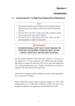
1
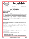
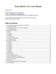
HI-6100 Field Monitor User Manual HI-6100 Field Monitor shown with optional probes ETS-Lindgren, Inc. reserves the right to make changes to any product described herein in order to improve function, design, or for any other reason. Nothing contained herein shall constitute ETS-Lindgren, Inc. assuming any liability whatsoever arising out of the application or use of any product or circuit described herein. ETS-Lindgren, Inc. does not convey any license under its patent rights or the rights of others. © Copyright 2006–2012 by ETS-Lindgren, Inc. All Rights Reserved. No part of this document may be copied by any means without written permission from ETS-Lindgren, Inc. Trademarks used in this document: The ETS-Lindgren logo is a trademark of ETS-Lindgren, Inc. Revision Record | MANUAL,HI-6100 | Part #H-600099, Rev. F ii Revision Description Date A Initial release January, 2006 B Add CE, update Set Up section June, 2006 C Revise to current style standards June, 2008 D Update outer dimensions, Physical Specifications section; Update System Menu and Find Probes sections May, 2010 E Updated back panel connectors March, 2012 F Updated field probe kits in Optional Items; added information about laser safety interlock mechanism to Introduction. December, 2012 | Table of Contents Table of Figures ....................................................................... vi Notes, Cautions and Warnings ............................................... vii General Safety Considerations ............................................. viii 1.0 Introduction .......................................................................... 9 Standard Configuration ............................................................................. 10 Optional Items .......................................................................................... 10 ETS-Lindgren Product Information Bulletin ............................................... 11 2.0 Maintenance ....................................................................... 13 Annual Calibration .................................................................................... 13 Laser Probes and Maintenance of Fiber Optics......................................... 14 Cleaning Instructions ........................................................................ 14 Handling Instructions ........................................................................ 15 Upgrade Policies....................................................................................... 15 Service Procedures .................................................................................. 15 3.0 Specifications ..................................................................... 17 Electrical Specifications ............................................................................ 17 Physical Specifications ............................................................................. 17 4.0 Assembly and Installation ................................................ 19 Set Up Procedure ..................................................................................... 19 Battery Probe Set Up ........................................................................ 19 Laser Probe Setup ............................................................................ 20 Remote Connections ................................................................................ 21 Mounting the HI-6100 in a Rack ................................................................ 21 Mounting Data Modules ............................................................................ 22 5.0 Operation ............................................................................ 25 Back Panel ............................................................................................... 25 Front Panel ............................................................................................... 26 HI-6100 Menu Options .............................................................................. 26 Overview of HI-6100 Menu Options .......................................................... 27 HI-6100 Display ........................................................................................ 28 Previous Option ................................................................................ 28 Find Probes Menu............................................................................. 29 | iii Probe Menu ...................................................................................... 30 —Temperature Units ................................................................. 30 —MinMax Reset ....................................................................... 31 —Range ................................................................................... 32 —Axis Enable ........................................................................... 32 Display Menu .................................................................................... 33 —Channel Enable ..................................................................... 33 —Probe Parameter ................................................................... 35 —Lower Display ........................................................................ 36 —Color ..................................................................................... 37 Remote Menu ................................................................................... 38 —GPIB Address........................................................................ 38 —RS-232 Baud ......................................................................... 39 System Menu .................................................................................... 40 —Set Time ................................................................................ 40 —Reset..................................................................................... 41 —More ...................................................................................... 41 —Software ................................................................................ 42 —Mode ..................................................................................... 43 —Update Software .................................................................... 44 —GPIB Output Mode ................................................................ 45 GPIB Status Menu ............................................................................ 46 6.0 Remote Operation .............................................................. 47 IEEE-488 Requirements ........................................................................... 47 Command Set Format............................................................................... 47 IEEE-488 (GPIB) Communications ........................................................... 48 RS-232 Communications .......................................................................... 48 RS-232 Settings........................................................................................ 48 Remote Commands .................................................................................. 50 —Read Probe ........................................................................... 50 iv | —Read Battery Voltages ........................................................... 51 —Read Peak ............................................................................ 51 —Reset Peak ............................................................................ 51 —Read Temperatures............................................................... 52 —Setup Recall .......................................................................... 52 —Setup Save............................................................................ 53 —Software Revision.................................................................. 53 —Verbose Mode ....................................................................... 54 —Last Errors............................................................................. 54 —Channel Enable ..................................................................... 55 —Local Mode ............................................................................ 55 7.0 Error Handling and Troubleshooting ............................... 57 Error Handling .......................................................................................... 57 Troubleshooting ........................................................................................ 57 Appendix A: Warranty ............................................................. 59 Appendix B: EC Declaration of Conformity .......................... 61 Appendix C: Commands ......................................................... 63 IEEE 488.2 Commands ............................................................................ 63 Standard Commands ................................................................................ 63 Appendix D: Commands in FM5004 Mode ............................ 65 Unsupported Commands in FM5004 Mode ............................................... 65 Alarm Functions ................................................................................ 65 Analog Output Functions................................................................... 66 Other Commands.............................................................................. 66 FM5004 Commands ................................................................................. 67 IEEE 488.2 Commands..................................................................... 67 Supported Commands ...................................................................... 68 Unsupported Commands .................................................................. 69 Appendix E: GPIB Register ..................................................... 71 | v Table of Figures Figure 1: Figure 2: Figure 3: Figure 4: Figure 5: Figure 6: Figure 7: Figure 8: Figure 9: Figure 10: Figure 11: Figure 12: Figure 13: Figure 14: Figure 15: Figure 16: Figure 17: Figure 18: Figure 19: Figure 20: Figure 21: Figure 22: Figure 23: Figure 24: Figure 25: Figure 26: Figure 27: Figure 28: Figure 29: Figure 30: Figure 31: Figure 32: Figure 33: Figure 34: Figure 35: Figure 36: vi | HI-6100 Field Monitor ......................................................... 9 HI-6100 Module Locations ................................................ 22 Optical Data Module .......................................................... 22 Laser Data Module ............................................................. 23 HI-6100 Back Panel ........................................................... 25 HI-6100 Front Panel (shown with optional case) ............... 26 Overview of HI-6100 Menu Options ................................. 27 Previous Option On Each Menu ......................................... 28 Find Probes Menu .............................................................. 29 Probe Menu ........................................................................ 30 Probe Menu—Temperature Units Selection....................... 30 Probe Menu—Min/Max Reset ........................................... 31 Probe Menu—Range .......................................................... 32 Probe Menu—Axis Enable ................................................. 32 Display Menu ..................................................................... 33 Display Menu—Channel Enable ........................................ 33 Channel Enable Selected—Three Channel Displays .......... 34 Display Menu—Probe Parameter ....................................... 35 Display Menu—Lower Display ......................................... 36 Display Menu—Color ........................................................ 37 Remote Menu ..................................................................... 38 Remote Menu—GPIB Address .......................................... 38 Remote Menu—RS-232 Baud............................................ 39 System Menu ...................................................................... 40 System Menu—Set Time ................................................... 40 System Menu—Reset ......................................................... 41 System Menu—More ......................................................... 41 System, More Menu—Software ......................................... 42 System, More Menu—Mode .............................................. 43 System, More Menu—Update Software ............................ 44 System, More Menu—GPIB Output Mode ........................ 45 GPIB Status ........................................................................ 46 System, GPIB Status Menu—Remote/Local...................... 46 RS-232 Communication Settings Table ............................. 48 HI-6100 Pin # Designations Table ..................................... 49 GPIB Registers ................................................................... 71 Notes, Cautions and Warnings Note: Denotes helpful information intended to provide tips for better use of the product. Caution: Denotes a hazard. Failure to follow instructions could result in minor personal injury and/or property damage. Included text gives proper procedures. Warning: Denotes a hazard. Failure to follow instructions could result in SEVERE personal injury and/or property damage. Included text gives proper procedures. See the ETS-Lindgren Product Information Bulletin for safety, regulatory, and other product marking information. | vii General Safety Considerations Caution: Uninsulated voltage within the unit may have sufficient magnitude to cause electric shock. Therefore, it is dangerous to make any kind of contact with any parts inside this unit. Warning: This is a Safety Class I product (provided with a protective earthing ground incorporated in the power cord). The mains plus shall only be inserted in a socket outlet provided with a protective earth contact. Any interruption of the protective conductor, inside or outside the instrument, is likely to make the instrument dangerous. Intentional interruption is prohibited. DO NOT defeat the earth grounding protection by using an extension cable, power cable, or autotransformer without a protective ground conductor. See the ETS-Lindgren Product Information Bulletin for safety, regulatory, and other product marking information. viii | 1.0 Introduction The ETS-Lindgren HI-6100 Field Monitor is a broadband electric and magnetic field probe monitor designed for use in radio frequency interference/electromagnetic compatibility (RFI/EMC) test system applications. It accepts inputs from up to four isotropic field probes and analyzes and displays that information on a user-configurable LCD display. It also provides two digital interfaces: IEEE-488 and RS-232. Figure 1: HI-6100 Field Monitor The HI-6100 is compatible with ETS-Lindgren electric (E) field or magnetic (H) field probes or laser probes. It has a probe-dependent frequency response of 10 kHz to 40 GHz and a probe-dependent sensitivity of 0.5 V/m to 3000 V/m, 15.0 mA/m to 30 A/m. The HI-6100 incorporates a safety interlock mechanism that turns off the laser if it does not receive data from the probe within a specified time frame. The safety mechanism is intended to prevent injury from the laser if the HI-6100 issues a command to turn on the laser while the fiber optic cables are disconnected, improperly connected, cut, or damaged. The HI-6100 in native HI-6100 mode is the preferred method for use with the laser-powered field probes as well as the HI-60XX Series battery-powered field probes. The HI-6100 in FM5004-compatible mode is primarily used with the HI-44XX Series probes for backward portability. Introduction | 9 Standard Configuration ETS-Lindgren may substitute a similar part or new part number with the same functionality for another part/part number. Contact ETS-Lindgren for questions about part numbers and ordering parts. Part Description Part Number HI-6100 Field Monitor HI-6100 Shipping End Caps H-390076 Power Cord Contact ETS-Lindgren Customer Service for power cord part number for your configuration Optional Items ETS-Lindgren may substitute a similar part or new part number with the same functionality for another part/part number. Contact ETS-Lindgren for questions about part numbers and ordering parts. Part Description Part Number Bench Top Case H-491271 Laser Pro Kits HI-6105FM HI-6153FM HI-6122FM Field Probe Kits HI-6053FM HI-6022FM HI-6005FM 10 Probe Stand H-491269 SMA Feedthrough H-231205000 FC Feedthrough H-23861521000 ST Feedthrough 708027 | Introduction Part Description Part Number Fiber Optic Cable (SMA) H-491106-XX Fiber Optic Cable (FC/ST) H-491263-XX Cleaning Kit H-34F01 ETS-Lindgren Product Information Bulletin See the ETS-Lindgren Product Information Bulletin included with your shipment for the following: Warranty information Safety, regulatory, and other product marking information Steps to receive your shipment Steps to return a component for service ETS-Lindgren calibration service ETS-Lindgren contact information Introduction | 11 This page intentionally left blank. 12 | Introduction 2.0 Maintenance Before performing any maintenance, follow the safety information in the ETS-Lindgren Product Information Bulletin included with your shipment. WARRANTY Maintenance of the HI-6100 is limited to external components such as cables or connectors. Clean the exterior of the cabinet using a damp cloth and mild cleaner. Always unplug the unit before cleaning. To prevent electrical shock, do not remove cover. Warranty may be void if the housing is opened. Any task that requires disassembly of the HI-6100 should be performed at the factory. If you have any questions concerning maintenance, contact ETS-Lindgren Customer Service. Annual Calibration Probes used with the HI-6100 Field Monitor require annual calibration to verify that they are performing within specifications. See the Product Information Bulletin included with your shipment for information on ETS-Lindgren calibration services. Maintenance | 13 Laser Probes and Maintenance of Fiber Optics The fiber optic connectors and cables used with laser-powered probes can be damaged from airborne particles, humidity and moisture, oils from the human body, and debris from the connectors they plug into. Always handle connectors and cables with care, using the following guidelines. Before performing any maintenance, disconnect the fiber optic cables from the unit and turn off power. When disconnecting fiber optic cables, apply the included dust caps to the ends to maintain their integrity. Before connecting fiber optic cables, clean the connector tips and in-line connectors. Before attaching in-line connectors, clean them with moisture-free compressed air. Failure to perform these tasks may result in damage to the fiber optic connectors or cables. CLEANING INSTRUCTIONS See an online demonstration of the proper cleaning procedure at www.ets-lindgren.com/FiberCleaning. 14 When handling fiber optic cables and connectors it is important that the mating connectors, fiber tip, and ferrule be cleaned before inserted into the fiber optic system. To clean the sides of the ferrule, use a folded lens-grade, lint-free tissue saturated in industrial grade isopropyl alcohol. Place the connector ferrule in the folded tissue, and apply pressure to the sides of the ferrule. Rotate the ferrule several times to remove all contamination from the ferrule sides. | Maintenance Use the cleaning tape shipped with the HI-6105 kit for cleaning the end face of the connector. Softly press the connector face on the exposed cleaning tape and move in a figure eight motion. After three figure eights inspect with a microscope and repeat if necessary. The mating connectors such as bulkhead feedthrough, transmit, and receive ports can be cleaned with canned dry air. Fiber optic connectors should be cleaned every time they are mated and unmated. HANDLING INSTRUCTIONS Never touch the end face of the connector. Connectors not in use should be covered over the ferrule by a plastic dust cap or boot. These boots will protect the polished ferrule end from damage but not contamination. It is important to note that inside the dust cap there is a sticky residue that is a by-product of making the dust cap. This residue will remain on the ferrule end after the cap is removed. Always clean fiber connectors and mating connectors prior to installation. Upgrade Policies System upgrades are made periodically to enhance functionality. Contact ETS-Lindgren Customer Service or see www.ets-lindgren.com to determine the upgrade status of your measurement system. Service Procedures For the steps to return a system or system component to ETS-Lindgren for service, see the Product Information Bulletin included with your shipment. Maintenance | 15 This page intentionally left blank. 16 | Maintenance 3.0 Specifications Electrical Specifications Nominal AC Voltage: 115/230 V Input Frequency: 50/60 Hz Maximum Output Power: 250 W Physical Specifications Outer Dimensions: Length: 48.3 cm (19 in) Width: 35.6 cm (14 in) Height: 13.3 cm (5.25 in) Approximate Weight: 5.9 kg (13 lb) Approximate Weight, including Optional Bench Top Case: 11.8 kg (26 lb) Specifications | 17 This page intentionally left blank. 18 | Specifications 4.0 Assembly and Installation Before connecting or operating any components, follow the safety information in the ETS-Lindgren Product Information Bulletin included with your shipment. Prior to assembly and installation, see Cleaning Instructions on page 14 and Handling Instructions on page 15. Set Up Procedure Perform the following procedures to verify system operation before installation in the test environment. BATTERY PROBE SET UP 1. Make sure the battery powered probes are fully charged. See the probes manual for charging information. If laser probes are to be used, read the probes manual to become familiar with the operation. See Laser Probe Setup on page 20 for detailed information. 2. Remove the plastic caps from the appropriate RF SENSOR I/O connectors on the back panel of the receiver. Remove the protective covers from the fiber optic cable assembly. Save all protective caps and covers for future use. 3. Visually inspect and clean the tips of the fiber optic cables to verify they are free from dirt or other contaminants. Connect the fiber optic cable to the RF SENSOR I/O connector pair, matching the cable connector colors to those on the receiver connectors (yellow to XMIT, white to RCV). 4. Connect the other end of the fiber optic cable to the sensor connectors: white to XMIT, yellow to RCV. The fiber connectors on the HI-60XX Series probes are permanently attached. Assembly and Installation | 19 5. Connect the AC power cord to the IEC connector on the back of the HI-6100 Field Monitor. Verify the power supply switch is in the ON position. 6. Plug the other end of the power cord into an electrical outlet. 7. Turn on the battery powered probe(s). 8. Turn on the power switch on the front panel. It may take several seconds for the display to appear. 9. To display the probes attached, press the Find All Probes key on the main menu of the display screen to see information for all of the probes. LASER PROBE SETUP 20 1. Remove the plastic dust caps from the appropriate DEVICE INTERFACE CHANNEL located on the back of the HI-6100. Save all protective caps and covers for future use. Clean transmit and receive ports using canned dry air. 2. Remove the dust caps from the probe and follow the instructions on page 14 to clean the fiber connectors. If extension cables and bulkhead feedthrough connectors will be used, clean as described. Connect the fiber optic cable to the selected DEVICE INTERFACE CHANNEL. Both the FC and the ST connectors are keyed. 3. Connect the AC power cord to the IEC connector on the back of the HI-6100. Verify the power supply switch is in the ON position. 4. Plug the other end of the power cord into an electrical outlet. 5. Turn on the power switch on the front panel. It may take several seconds for the display to appear. 6. To display the probes attached, press the Find All Probes key on the main menu of the display screen to see information for all of the probes. | Assembly and Installation Remote Connections For remote-controlled operation of the HI-6100 connect the RS-232 or IEEE-488 cable to the appropriate connector. If RS-232 remote control is used, see Remote Operation on page 47 for information on setting the device baud rate. If IEEE-488 remote control is used, set the DEVICE ADDRESS to the appropriate bus address for your installation. See Operation on page 25 for information on setting the device address. Test remote operation by issuing an *IDN? command from the remote controller (*IDN?<LF>) and verify that the HI-6100 returns the proper response. See Remote Operation on page 47 for additional information. Mounting the HI-6100 in a Rack This product is designed for use in Installation Category II and Pollution Degree II per IEC-1010 and IEC-664. When installing the HI-6100 in a rack the convection into and out of the product must not be restricted. The ambient temperature (outside of the rack) must be less than the maximum operating temperature of the HI-6100 by 4°C for every 100 Watts dissipated in the rack. If the total power dissipated in the cabinet is greater than 800 Watts, then forced convection must be used. Assembly and Installation | 21 Mounting Data Modules Optical data modules or laser data modules may be mounted on any available channel. Figure 2: HI-6100 Module Locations Figure 3: Optical Data Module 22 | Assembly and Installation Figure 4: Laser Data Module 1. Remove the cover by removing the two screws on the back panel and the nut on the laser data module angle bracket, if installed. 2. Place the new module in the desired channel location and secure with two screws on the back panel and the nut on a laser data module angle bracket, if available. 3. Attach one end of the data module cable to the data module and the other end to the corresponding channel and data module interface board. Assembly and Installation | 23 This page intentionally left blank. 24 | Assembly and Installation 5.0 Operation This instrument is shipped with a three-wire power cable, in accordance with international safety standards. When connected to an appropriate power line outlet, this cable grounds the instrument cabinet. Back Panel Do not block the power supply fan. It must remain unobstructed at all times. Figure 5: HI-6100 Back Panel The back panel of the HI-6100 Field Monitor includes: Dedicated connection ports—IEEE-488 GPIB, RS-232, and Update. Device label locations—Place the warning label shipped with each probe in these marked locations. Device Interface—Four interface slots (Channel 1, Channel 2, Channel 3, Channel 4) to accommodate up to four probes. Operation | 25 Front Panel Figure 6: HI-6100 Front Panel (shown with optional case) The front panel of the HI-6100 includes: Display—Enables the user to see the active probe(s). Function keys (6)—Allow the user to easily navigate the menus of the controller. Power button—Includes an indicator light allowing the user to easily verify if the unit is on or off. To turn off the HI-6100, press and hold the power button for three to four seconds. HI-6100 Menu Options On the page 27 is an illustration of the HI-6100 menu hierarchy. The illustration serves as an overview or map of the menu options; the remainder of this chapter describes each option. 26 | Operation Overview of HI-6100 Menu Options Figure 7: Overview of HI-6100 Menu Options Operation | 27 HI-6100 Display PREVIOUS OPTION Select Previous at the top of each menu series to return to the previous screen and, eventually, to the main menu. Figure 8: Previous Option On Each Menu 28 | Operation FIND PROBES MENU The HI-6100 display simultaneously exhibits up to four probes. Select Find Probes to automatically display the number of probes that are enabled. The system will search each channel, determine which of the enabled channels are active, and then display those channels. Figure 9: Find Probes Menu To enable a channel, see the Display Menu on page 33. When selections are made in the menu they are immediately saved. Only enabled channels will be detected by selecting Find Probes. To maximize the system performance, only enable the channels that contain active probes. Operation | 29 PROBE MENU Selecting Probe provides several choices that relate directly to the information available for the probe(s) in use. Figure 10: Probe Menu —Temperature Units Select Temperature Units to toggle between Fahrenheit and Celsius temperature readings. Figure 11: 30 | Probe Menu—Temperature Units Selection Operation —MinMax Reset Select Min/Max Reset to reset the individual probe values. Please note that the min/max values may not be visible. Figure 12: Probe Menu—Min/Max Reset The Range and Axis Enable options under the Probe menu will only appear when the mode is set to FM5004 under the Systems menu. Operation | 31 —Range Select Range to manually set the range. The HI-6XXX probe range is not adjustable; these are single range probes. Figure 13: Probe Menu—Range —Axis Enable Use Axis Enable to select the channel or probe to be adjusted and the axis to be enabled or disabled. Figure 14: 32 | Probe Menu—Axis Enable Operation DISPLAY MENU Select Display from the main menu to customize the display. Figure 15: Display Menu —Channel Enable Choose Channel Enable from the display menu to manually select the channel(s) to view on the display. Up to four channels may be viewed on one screen. Figure 16: Display Menu—Channel Enable Operation | 33 Once Channel Enable is selected, the user may distinguish which channels are currently on/off by selecting the screen where each channel and their status are noted. In addition, the user has the option to turn on/off a channel by pressing that channel button. To maximize the system performance, only enable the channels that contain active probes. Figure 17: 34 | Channel Enable Selected—Three Channel Displays Operation —Probe Parameter When selecting Probe Parameter, the lower right corner of the active channel screen(s) will toggle between parameters, min/max/avg, and laser warning views. When the program is closed, upon re-starting the system the display automatically appear as it was last configured. Figure 18: Display Menu—Probe Parameter Operation | 35 —Lower Display Lower Display corresponds to the window shaded gray at the bottom of the display. By pressing the button for this option, the system will toggle between the probe, min/max/avg for all active probes, controller error, and probe error information. When the controller and probe error readouts are selected, the last six errors the system experienced will be visible. Figure 19: 36 | Display Menu—Lower Display Operation —Color Select Color to scroll through several pre-determined color schemes. These color schemes are designed to allow optimal display of the monitor information accommodating unique user environments. Figure 20: Display Menu—Color Operation | 37 REMOTE MENU Select Remote to set the communication parameters. Figure 21: Remote Menu —GPIB Address By selecting GPIB Address in the Remote menu, the address will scroll between 31 available addresses. Figure 22: 38 | Remote Menu—GPIB Address Operation —RS-232 Baud Select RS-232 Baud to set the baud rate for the external serial ports. Figure 23: Remote Menu—RS-232 Baud Operation | 39 SYSTEM MENU Select System to access systems settings. Figure 24: System Menu —Set Time Select Set Time to set the time. Figure 25: 40 | System Menu—Set Time Operation —Reset Select Reset to return the HI-6100 to the factory default configuration. Figure 26: System Menu—Reset —More Select More to display a list of additional system selections. Figure 27: System Menu—More Operation | 41 —Software For informational purposes only. The button has no effect. Figure 28: 42 | System, More Menu—Software Operation —Mode Allows the HI-6100 to operate as an FM5004 field monitor. Figure 29: System, More Menu—Mode In this mode the HI-6100 will communicate with the FP2000, FP5000, HI-6000, and HI-4400 series of probes. See Appendix D on page 65 for a list of supported FM5004 commands. In the HI-6100 mode only the HI-6000 series probes are supported and a new GPIB command set is utilized. See Appendix C on page 63 for HI-6100 commands. Operation | 43 —Update Software Allows the user to upgrade the software. Figure 30: System, More Menu—Update Software To download and install upgrades for the HI-6100 operating system: Go to www.ets-lindgren.com. On the Resources menu, click Software/Firmware. Find the HI-6100 upgrade file in the Software column and follow the on-screen instructions to download. Follow the instructions included with the file to install the updated software. Any changes made to the system setup are automatically saved. 44 | Operation —GPIB Output Mode Allows the user to configure the HI-6100 to format the output data while in FM5004 mode. The 4-Lines setting requires four consecutive reads (ibrd). The 1-Line setting requires a single read. This setting has no effect when the HI-6100 mode is selected. Figure 31: System, More Menu—GPIB Output Mode Operation | 45 GPIB STATUS MENU GPIB Status allows the user to return the HI-6100 to local mode. This enables all other menu functions. Figure 32: GPIB Status Select Remote/Local to toggle between the two selections. Figure 33: 46 | System, GPIB Status Menu—Remote/Local Operation 6.0 Remote Operation Before connecting or operating any components, follow the safety information in the ETS-Lindgren Product Information Bulletin included with your shipment. This chapter describes remote operation of the HI-6100 Field Monitor using either the IEEE-488 parallel port or the RS-232 serial port connected to a remote device, such as an IEEE-488 bus or a personal computer. IEEE-488 Requirements For IEEE-488 operation, the device address is set to 4 at the factory. Command Set Format Each command or query code is composed of four alpha characters and optional numerical parameters. When a query is received, the receiver returns a string consisting of the query followed by the current setup for that command. Commands can be entered in upper or lower case. A line feed, <LF>, terminates all commands. To include several commands in a single command string, separate each command by a semicolon (delimiter). Do not include spaces between a command and its associated numeric parameter. Data returned from the receiver will be terminated with a <CR><LF>. Remote Operation | 47 IEEE-488 (GPIB) Communications For General Purpose Interface Bus (GPIB) communications, the End or Identify (EOI) control line may also be used for command termination. Terminate the command with <LF>, EOI, or both when sending commands to the receiver via the GPIB. No characters are permitted after <LF> or EOI; the system interprets characters following <LF> or EOI as the start of another command. When an error condition is present at the receiver, the service request (SRQ) signal is asserted. The operator can then perform a serial poll operation. The receiver error code (in binary) is contained in the lower bits of the serial poll status byte. If the receiver is addressed as a listener and the GPIB remote line is asserted, the receiver will switch to remote mode. RS-232 Communications Commands are processed in a manner very similar to that of the IEEE interface. The command structure is identical, except that an EOI line does not exist; therefore, <LF> must terminate all commands. When a valid command is received, it is processed and the result is immediately transmitted back over the RS-232 interface. The output format is identical to that of the IEEE format except, again, an EOI line does not exist. RS-232 Settings 48 Word Length 8 bits Stop Bits 1 Baud Rate 1200 – 115,200 (menu selectable) Parity None Figure 34: RS-232 Communication Settings Table | Remote Operation Signifies output from the HI-6100 Signifies input to the HI-6100 HI-6100 Pin # Signal Data Direction 1 DCD Device Carrier Detect 2 RD Receive Data 3 TD Transmit Data 4 DTR Data Terminal Ready 5 GND N/A Description Ground 6 NC N/A No Connection 7 RTS Ready to Send 8 CTS Clear to Send 9 NC N/A No Connection Figure 35: HI-6100 Pin # Designations Table A null modem cable or adapter (supplied by the user) is required for interfacing the HI-6100 to a standard serial port on a computer. Remote Operation | 49 Remote Commands The commands described in the following pages are available to the user for remote communications with the HI-6100. The following conventions are used: 1. A lower case x in the command or returned data syntax represents a numeric value. 2. A lower case n in the command or returned data syntax represents a channel number (1 through 4) associated with a system probe. 3. A lower case m in the command or returned data syntax represents a mode selection. —Read Probe Writes the current probe field values to a remote port. Syntax: RPRB,x Parameters: (x) 0 = Reads all channels 3 = Reads channel 3 1 = Reads channel 1 4 = Reads channel 4 2 = Reads channel 2 5 = Reads minimum, maximum and average of all active probes Output format: xx.xxuuuuuuoca,xx.xxuuuuuuoca,,<CR><LF> Each axis or channel data block consists of a fourteen-character string. The first comma-separated data block is the sum of all axis followed by X, Y, and then Z axis. The over/under range character will be blank, U or O. The axis character will be c,x,y,z or blank. 50 | Remote Operation —Read Battery Voltages Returns the current battery percentages of probes in use. Syntax: RBAT? Parameters: None To check the current battery percent of the probes in use: RBAT?<LF> Response: 62%,100%,,<CR><LF> Channels 3 and 4 are not on or not ready. —Read Peak Writes the peak probe field values to a remote port. Syntax: RDPK,x Parameters: (x) 1 = Reads channel 1 max 5 = Reads channel 1 min 2 = Reads channel 2 max 6 = Reads channel 2 min 3 = Reads channel 3 max 7 = Reads channel 3 min 4 = Reads channel 4 max 8 = Reads channel 4 min Output format: Ch1 Max xx.xx,Xxx.xx,Yxx.xx,Zxx.xx<CR><LF> —Reset Peak Resets peak probe field values. Syntax: RSPK Parameters: None Remote Operation | 51 —Read Temperatures Returns the current temperature reading from the probes in use. Syntax: RTMP? Parameters: None To check the current temperature of the probes in use: RTMP?<LF> Response: 77F,100F,,<CR><LF> Channels 3 and 4 are not on or not ready. —Setup Recall Recalls a saved HI-6100 setup. Syntax: RECL,x Parameters: (x) 1 = Recall setup #1 3 = Recall setup #3 2 = Recall setup #2 4 = Recall setup #4 To recall setup #1 and change to the setup configuration #1: RECL,1<LF> 52 | Remote Operation —Setup Save Saves the HI-6100 current configuration into memory. Syntax: SAVE,x Parameters: (x) 1 = Saves to setup #1 3 = Saves to setup #3 2 = Saves to setup #2 4 = Saves to setup #4 To save the current configuration to setup #1: SAVE,1<LF> The setup will be saved to memory and can be recalled with the command RECL,1. —Software Revision Returns the current revision of the HI-6100 operating software. Syntax: SREV Parameters: None To check the current revision of the HI-6100 software: SREV?<LF> Response: SREV,1.0<CR><LF> Remote Operation | 53 —Verbose Mode Sets the HI-6100 to respond to all remote commands or to respond to inquiries only. Syntax: VERB,x Parameters: (x) 0 = Verbose mode disabled 1 = Verbose mode on Examples To enter verbose mode: VERB,1<LF> Response: -VERB,1<CR><LF> To disable verbose mode: VERB,0<LF> Response: The HI-6100 will not respond (verbose mode off). —Last Errors Syntax: LERR? Parameters: None To see the last errors: LERR?<LF> Response 54 The HI-6100 will respond with the same information as displayed in the GPIB and probe list box errors. If no errors are logged, the HI-6100 will respond with: NO errors logged.<CR><LF> | Remote Operation —Channel Enable Used to set a channel on or off. This command should not be used to toggle a channel on and off frequently. Probes may require several seconds to reinitialize. Syntax: CHAN,m,n Parameters: Channel number (m) on/off (n): 1 = Channel 1 3 = Channel 3 2 = Channel 2 4 = Channel 4 To enable channel 1: CHAN,1,1<LF> —Local Mode Returns the HI-6100 to local mode when it is in remote mode. Local mode allows the operator to use the front panel buttons. Syntax: LOCL,x Parameters: Local mode enable (x) 0 = Local mode disabled 1 = Local mode enabled To return the HI-6100 to local mode (front panel buttons become operational): LOCL,1<LF> Remote Operation | 55 This page intentionally left blank. 56 | Remote Operation 7.0 Error Handling and Troubleshooting Error Handling The user interface display contains two error list boxes. These error list boxes may be displayed from the DISPLAY menu by selecting LOWER DISPLAY. If any errors have occurred since the system was powered on, each box will display up to the last six error messages. Troubleshooting Following are some common troubleshooting tips for the HI-6100 Field Monitor. If you have a problem not listed or if the corrective action fails, contact ETS-Lindgren Customer Service. Indication Possible Cause / Corrective Action Probe fails to communicate with HI-6100 Fiber optic cable reversed: Confirm cable is connected properly Dirty fiber optic cable ends: Clean to remove dirt or contaminants Bad cable or faulty connector: Replace cable Dead battery: Charge battery HI-6100 fails to power up Power cord unplugged or faulty: Confirm cable is connected properly. To replace cord, contact Customer Service. Error Handling and Troubleshooting | 57 This page intentionally left blank. 58 | Error Handling and Troubleshooting Appendix A: Warranty See the Product Information Bulletin included with your shipment for the complete ETS-Lindgren warranty for your HI-6100. DURATION OF WARRANTIES FOR THE HI-6100 All product warranties, except the warranty of title, and all remedies for warranty failures are limited to three years. Product Warranted Duration of Warranty Period HI-6100 Field Monitor 3 Years Warranty | 59 This page intentionally left blank. 60 | Warranty Appendix B: EC Declaration of Conformity EC Declaration of Conformity | 61 This page intentionally left blank. 62 | EC Declaration of Conformity Appendix C: Commands For a list of FM5004 compatibility commands, see Appendix D: Commands in FM5004 Mode on page 65. IEEE 488.2 Commands Command Description *CLS Clear status *ESE Event status enable *ESR Event status register *IDN Identification query *OPC Operation complete query *RST Reset *SRE Service request enable *STB Read status byte *TST Self-test query *WAI Wait to continue Standard Commands Command Description CHAN Channel enable LERR Last error LOCL Local RBAT Read battery voltages RECL Recall RPRB Read probe RTMP Read probe temperatures SAVE Save setup Commands | 63 64 Command Description SREV Software revision RDPK Read min/max peak RSPK Reset min/max peak VERB Verbose mode | Commands Appendix D: Commands in FM5004 Mode Unsupported Commands in FM5004 Mode The following commands are not supported in either the HI-6100 mode or the FM5004 mode. In general, the HI-6100 Field Monitor does not have alarm or analog output capabilities. Functions to adjust the LCD and the display have also been removed. ALARM FUNCTIONS Alarm functions are not available on the HI-6100. These commands are included for test software compatibility purposes only and have no effect on the HI-6100. An error entry will be added to the CONTROLLER COMMUNICATIONS error list. Command Response Alarm Latch Where m is equal to the alarm mode: ALAT,m,0<LF> Alarm Silence Where m is equal to the alarm mode: ALOE,m,0<CR><LF> Alarm Lower Enable — Alarm Lower Value Where m is equal to the alarm type: ALOV,m,0<CR><LF> Alarm Upper Enable Where m is equal to the alarm type: AUPE,m,0<CR><LF> Alarm Upper Value Where m is equal to the alarm type: AUPV,m,0<CR><LF> Commands in FM5004 Mode | 65 ANALOG OUTPUT FUNCTIONS Analog output functions are not available on the HI-6100. These commands are included for test software compatibility purposes only and have no effect on the HI-6100. An error entry will be added to the CONTROLLER COMMUNICATIONS error list. Command Response Analog Output Mode ANAO,0<CR><LF> Analog Output Range ANAR,0<CR><LF> OTHER COMMANDS These commands are included for test software compatibility purposes only and have no effect on the HI-6100. An error entry will be added to the CONTROLLER COMMUNICATIONS error list. Command Response Alternate Display Format — Buss Voltage +12 - +12.00<CR><LF> +5V - +5.00<CR><LF> -12 - -12.00<CR><LF> Filter Size FTSZ,10<CR><LF> Key Click — LCD Brightness — LCD Contrast — Log Scale — 66 | Commands in FM5004 Mode Command Response Sample Rate SMPR,00<CR><LF> The sample rate is probe-dependent and set run as fast as possible. System Alarm, Hard Probe Failure — System Alarm, Momentary Probe Failure — Display Update Rate DUPR,5<CR><LF> The display update rate is fixed at 7 samples/second. FM5004 Commands IEEE 488.2 COMMANDS Command Description *CLS Clear status *DDT Device trigger *ESE Event status enable *ESR Event status register *IDN Identification query *OPC Operation complete query *RST Reset *SRE Service request enable *STB Read status byte Commands in FM5004 Mode | 67 Command Description *TRG Trigger *TST Self-test query *WAI Wait to continue SUPPORTED COMMANDS 68 Command Description BAUD Baud rate entry CHRA Change probe range CLED Channel LEDS DSFM Display format GPIB GPIB address LERR Last errors LOCL Local RBAT Read battery voltage RDIS Read display RECL Recall RTMP Read probe temperature REMT Remote SREV Software revision SAVE Save setup VERB Verbose mode ZERO Zero probes | Commands in FM5004 Mode UNSUPPORTED COMMANDS Command Description ADFM Alt Display Format ALAT Alarm Latch ALOV Alarm Lower Value ALOE Alarm Lower Enable ALSR Alarm Silence ANAO Analog out ANAR Analog Range AUPE Alarm Upper Enable AUPV Alarm Upper Value BUSV Buss Voltage CLCK Key Click DATE Software Date DUPR Display Update Rate ERRQ Error Register Query FTSZ Filter Size HELP This command LCDB LCD brightness LCDC LCD Contrast LOGS Log Scale RDMD Read Display Mode SALH System Alarm Hard Probe Fail SALM System Alarm Momentary Fail SALS System Alarm System Fail SMPR Samples/second Commands in FM5004 Mode | 69 This page intentionally left blank. 70 | Commands in FM5004 Mode *ESR? *CLS PCN Figure 36: GPIB Register V *CLS V 7 6 7 6 PON Serial Poll CLR V V V V CLR V 0 *ESE (data) *ESE? V Standard Event Status Reg. 0 read by *ESR? | RQS S R Any Bits Standard Event Status Reg. 1 1 PON 3 2 3 2 All Bits 5 4 5 4 Operation Complete Request Control Query Error Device Dependant Error Execution Error Command Error User Request Power On For *STB? For Serial Poll 7 6 7 6 3 2 CLR 5 4 5 MAV 4 3 2 ESB Queue Not Empty Status Byte Register read by *STB? Service Request 0 Enable Reg. *SRE data *SRE? 0 PON 1 1 Appendix E: GPIB Register GPIB Registers 71