1
WebControl
TM
Programmable Logic
Controller
User Guide
Version:
3.3.19
Hardware Version:
2.3.x
Firmware Version:
3.03.19
Firmware datastamp:
4/16/2015
Doc last modified:
6/18/2015
WebControlTM PLC User Guide Version 3.03.19
Table of Contents
1
2
3
Introduction .......................................................................................................... 1
1.1
Scope............................................................................................................ 1
1.2
Table of Definitions ....................................................................................... 1
WebControlTM I/O ................................................................................................. 2
2.1
Power Supply Inputs ..................................................................................... 2
2.2
TTL Output Port ............................................................................................ 2
2.3
AUX Input Port .............................................................................................. 3
2.4
1-Wire Sensor Input ...................................................................................... 3
2.5
Humidity Sensor Input .................................................................................. 3
2.6
Spare Pin Header ......................................................................................... 4
WebControlTM PLC Web GUI Configuration ........................................................ 5
3.1
4
5
3.1.1
NTP Server Settings .............................................................................. 6
3.1.2
Access Settings ..................................................................................... 6
3.2
I/O Setup....................................................................................................... 8
3.3
X10 RF Control ........................................................................................... 10
3.4
Output Control ............................................................................................ 11
3.5
Notification Setup........................................................................................ 12
3.6
General Setup............................................................................................. 15
3.7
Reset Setup ................................................................................................ 16
AUX System Inputs ............................................................................................ 17
4.1
Digital Inputs ............................................................................................... 17
4.2
Analog Inputs .............................................................................................. 18
4.3
DS1822/DS18B20 1 Wire Temperature Sensors ....................................... 18
4.4
Maxim DS2438 Sensor ............................................................................... 18
4.5
Honeywell 4000 Series Relative Humidity Sensor...................................... 19
4.6
I2C Support................................................................................................. 19
4.7
SPI Support ................................................................................................ 19
4.8
Timers ......................................................................................................... 20
4.9
Direct Query System Inputs and Outputs ................................................... 20
Real Time Clock................................................................................................. 22
5.1
6
Network Settings........................................................................................... 5
Network Requirements to Use the NTP...................................................... 22
WebControlTM PLC Programming ...................................................................... 23
6.1
The Basics of PLC Programming ............................................................... 23
6.2
WebControlTM PLC Instructions .................................................................. 24
Copyright(C) 2008-2015 CAI Networks, Inc.
i
WebControlTM PLC User Guide Version 3.03.19
6.3
WebControlTM PLC I/O Identifiers .............................................................. 28
6.4
WebControl PLC Examples ........................................................................ 32
6.4.1
Example 1 Set Output based on condition .......................................... 32
6.4.2
Example 2: Flash TTL output ............................................................. 33
6.4.3
Example 3: Push Button Input Control Output ..................................... 33
6.4.4
Example 4: Send EMAIL ..................................................................... 33
6.4.5
Example 5, Parallel I/O ........................................................................ 34
6.4.6
Example 6, Sequential I/O ................................................................... 36
6.4.7
Example 7, Traffic Lights ..................................................................... 36
6.4.8
Example 8, Time based Control .......................................................... 38
6.4.9
Example 9, Battery Charger ................................................................ 40
6.4.10
Example 10, RFID reader and browser Control .................................. 42
6.4.11
Example 11, Bitwise Operation ........................................................... 43
6.4.12
Example 12, Angle Calculation............................................................ 43
6.4.13
Example 13, Non-Blocking Delay ........................................................ 43
6.4.14
Example 14, WEBSET to get server reply ........................................... 44
6.4.15
Example 15, Server CGI Handles WEBSET ....................................... 44
6.4.16
Example 13, I2C Slave Device Communication .................................. 45
6.4.17
WebControl
Example 14, SPI Device Communication ............................................ 46
TM
PLC FAQ ........................................................................................... 47
6.5
Login and Configuration.............................................................................. 47
6.6
Temperature Sensor Support ..................................................................... 47
6.7
Turn on/off TTL output from another programming language ..................... 48
6.8
External Analog Chip DS2450 .................................................................... 49
6.9
Power Supply Requirement ........................................................................ 49
Copyright(C) 2008-2015 CAI Networks, Inc.
ii
WebControlTM PLC User Guide Version 3.03.19
Table of Figures
Figure 1.0 WebControlTM PCB inputs and outputs diagram ........................................ 2
Figure 2.0 WebControlTM sensor connections ............................................................. 3
Figure 3.0 WebControlTM PLC system status .............................................................. 5
Figure 4.0 WebControlTM PLC Network configurable .................................................. 6
Figure 5.0 I/O setup .................................................................................................... 8
Figure 6.0 WebControlTM X10RF Control .................................................................. 10
Figure 6.0 WebControlTM Output Control .................................................................. 11
Figure 7.0 WebControlTM email setup ....................................................................... 13
Figure 8.0 Network defaults ...................................................................................... 15
Figure 9.0 WebControlTM J12 Input pins ................................................................... 17
Figure 10.0 WebControlTM Temperature sensor assignments .................................. 18
Copyright(C) 2008-2015 CAI Networks, Inc.
iii
WebControlTM PLC User Guide Version 3.03.19
1 Introduction
This document provides an overview of the technical aspects of using WebControlTM
8 PLC. It describes the inputs and outputs offered by the PLC version of the
WebControlTM hardware and firmware. The WebControl PLC function, usage and
syntax as well as many examples are provided there to help you get started. The
PLC version of firmware provides greater flexibility in I/O control; but in return,
expects user to learn programming concepts and write an assembly like PLC
program. A PLC program has the ability to read write and compare values of the
available inputs, outputs, variables and timers. With a PLC program loaded and
running, WebControlTM PLC can operate on its own, without a network connection.
The PLC programming module and programming guide are provided for a learn-onyour own experience. Assistance in writing or debugging PLC code is not provided
as part of the regular technical support for WebControlTM PLC configuration.
WebControlTM PLC 3-03-19 firmware backward compatible with 3.02.21 firmware. 302-21 supports hardware rev 2.2.2 board, 3-03-19 supports hardware rev 2.3.8. The
main differences are I2C and SPI terminal addition, and added other terminals.
1.1 Scope
The scope of this document is to be a guide for configuring and using the features
provided by WebControlTM . The reader is expected to be technically competent in all
the technical areas within this document, and is strongly advised to use this
document alongside the other reference material listed in the reference section.
1.2 Table of Definitions
The following table is a list of definitions used though out the document.
Definition
Description
HTTP
DNS
SMTP
SNTP
1-wire
RH
NetBios
Hypertext transfer protocol
Domain name server
Simple mail transport protocol
Simple network time protocol
Special bidirectional serial data bus from Maxim
Relative humidity
Human readable name used as an alternative to an IP address for
accessing the server on a network. E.g. http://WebControlTM
Internet protocol
Dynamic host configuration protocol
Read only memory
Programmable Logic Controller
IP
DHCP
ROM
PLC
Copyright(c) 2008,-2014 CAI Networks, Inc.
1
WebControlTM PLC User Guide Version 3.03.19
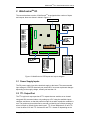
2 WebControlTM I/O
The current hardware version of WebControlTM is equipped with a number of inputs
and outputs; these are shown in below in figure 1.0.
Figure 1.0 WebControlTM PCB inputs and outputs diagram
2.1 Power Supply Inputs
The DC power supply input is the electrical supply to the board. The recommended
input voltage is 5-40V DC absolutely not exceed 40V. Its current reqirement changes
depending on the supply voltage, normally not less than 1A.
2.2 TTL Output Port
The TTL logic level output port has 8 TTL outputs that can each be set or cleared
using web GUI command codes, or by setting up a PLC using the available inputs,
variables, and timers, so that the particular output is set when a particular condition is
met. The maximum current that can be sourced or sinked by one of these outputs at
a time is 20mA or 100mA for the whole board. TTL 0 level defined as 0-2V and TTL
1 level is define 3-5V with TTL 0 almost 0V and TTL 1 almost 5V depending on the
Copyright(c) 2008,-2014 CAI Networks, Inc.
2
WebControlTM PLC User Guide Version 3.03.19
load. TTL output current is capable to drive standard solid state relay, but will not be
able to drive those coil based relays. Be aware of the current requirements of the
circuits/loads attached to these outputs. Damage will occur to the board if too much
current is allowed.
2.3 AUX Input Port
The AUX input connector offers digital and analog inputs that can be monitored or
programmed to set a single TTL output or several TTL outputs. Three analog inputs
are available, each have an input range of 0 to 10Vdc. Eight digital inputs are
available and use TTL input levels (0 and 5Vdc). The AUX Input Port pin out diagram
(labeled as J12AUX in Figure 1) shows the layout of this port in more detail. The
matching connector for this port is TYCO ELECTRONICS - 1658622-3 .
2.4 1-Wire Sensor Input
The 1-wire sensor port allows up to eight Maxim DS1822/DS18B20/DS18S20 1-wire
temperature sensors to be connected. It also allows one Maxim DS2417 real time
clock, and one DS2450 4 channel A/D converter. When DS2438 sensors are used, it
will take upper four DS18xy sensor location for temperature reading, and DS2450’s
analog inputs. The temperature and analog input can be displayed via the HTTP
browser and can be used as inputs to the PLC engine to control the TTL output port.
Since hardware revision 2.2.2 uses 5V to power 1-wire bus, there is no need for any
external power to the sensors. Please note if more than one DS2450 is attached to 1wire bus, only the first one will be used by the firmware. If more than 10 1-wire
devices attached to the bus, only the first 10 will be used.
2.5 Humidity Sensor Input
The current WebControlTM hardware has been designed to use the Honeywell 4000
series relative humidity sensor devices. Using any other humidity sensor without
careful consideration may result in malfunction of this feature. The RH sensor can be
used to display relative humidity via HTTP or be used to control the TTL outputs as
an input in the PLC engine.
Figure 2.0 WebControlTM sensor
connections
Please make sure the temp sensor
and humidity sensor connected
similar to this picture. Reverse the
polarity may cause damage to the
board.
Copyright(c) 2008,-2014 CAI Networks, Inc.
3
WebControlTM PLC User Guide Version 3.03.19
2.6 Spare Pin Header
There are 15 terminal on this header. Spare pin header has 3 groups. I2C group
Pin 1 = SCL
Pin 2 = SDA
Pin 3 = 5V
Pin 4 = GND
SPI bus group, most SPI devices requires 3V3 supply. If an enable pin required,
GPIO1 in next group can be used.
Pin 5 = GND
Pin 6 = 3V3
Pin 7 = MISO
Pin 8 = MOSI
Pin 9 = SCLK
And other group
Pin 10 = GPIO1
Pin 11 = GND
Pin 12 = GPIO2
Pin 13 = GND
Pin 14 = PLED
Pin 15 = GND
GPIO1 pin is not assigned any function, it can be controlled in PLC. GPIO2 pin
through J9 header normally is connected to the TTL output enable function, thus
during power on and bootloader time, TTL outputs are disabled. Removed J9 header
will disable GPIO2 control during power up. GPIO2 is pulled to TTL0 during
bootloader time, thus TTL output is disabled. This enabled users to use negative
going relay board. However, GPIO2 can not be used for anything else. If a positive
relay board is used, GPIO2 can be controlled in PLC for other purpose.
Copyright(c) 2008-2015 CAI Networks, Inc.
4
WebControlTM PLC User Guide Version 3.03.19
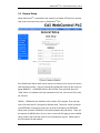
3 WebControlTM PLC Web GUI Configuration
To access WebControlTM PLC, connect WebControlTM to the local network and power
supply. The default IP address will be 192.168.1.15. Be aware that once you enable
DHCP in your WebControl network settings page, you will need to check your DHCP
server log for which IP address DHCP assigned to the board. You need to know and
understand the network you attaching this hardware to in order to know where to look
for DHCP server logs. For home networks, DHCP serving is commonly enabled at
the router. Each WebControlTM PLC board has a unique MAC address. Look in the
DHCP log to find the matching MAC address, then you can find the IP address
DHCP assigned to the hardware. From a computer connected to the same network,
start a web browser, and point to that IP address: for example: http://ww.xx.yy.zz
when the web page loads, you will be prompt for login. The default user ID and
password is: “admin/password”, all in lower case. You will see this page once
logged in:
Figure 3.0 WebControlTM PLC system status
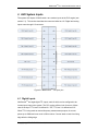
3.1 Network Settings
These are the basic settings that need to be configured in order for WebControlTM to
work successfully on a network. It may be necessary to connect the board directly to
Copyright(c) 2008-2015 CAI Networks, Inc.
5
WebControlTM PLC User Guide Version 3.03.19
a PC and access it using its default IP address before connecting directly to a live
network in order to configure it correctly. Figure 4.0 shows the Network settings
WebControlTM has.
Figure 4.0 WebControlTM PLC Network configurable
3.1.1 NTP Server Settings
This version changed from previous versions by reduced Allowed Limits host IP
address from eight to four. In addition, it added NTP Server section to allow user to
enter his local NTP server’s IP address to overwrite the default pool.ntp.org resolved
IP address. By default NTP server field should be 0.0.0.0, so that WebControlTM will
use pool.ntp.org as the Network Time Protocol server.
3.1.2 Access Settings
For security purpose, you can decide your own user name and password. For being
used over Internet, you may also set the access list, so that only host in the list can
Copyright(c) 2008-2015 CAI Networks, Inc.
6
WebControlTM PLC User Guide Version 3.03.19
access the WebControlTM board over the network. Please note that if any entry is
0.0.0.0, all IP addresses can access it.
Copyright(c) 2008-2015 CAI Networks, Inc.
7
WebControlTM PLC User Guide Version 3.03.19
3.2 I/O Setup
WebControlTM PLC allows users to directly from browser control each output, or
through the PLC logic to control the TTL output. For flexibility, user can decide if the
TTL input or out to be inverted between logic 0 and logic 1. To use PLC logic, first
user must check the “Global PLC enable” to start the PLC engine. Then for each
TTL output, user can decide if the PLC control will be applicable.
Figure 5.0 I/O setup
WebControlTM PLC allows user using browser to directly control the output state. If a
command line utility or third party control software used, you will need to enable the
Browser Control for that TTL output, also may need to go to network configuration to
disable the Web login (see figure 4.0).
The inverted state will be remembered in EEPROM even after power loss. The invert
state will be restored upon power resumed.
X10 Enable will allow user to send X10RF commands through TTL port8, once X10
is enabled. X10 transmitter used to be powered by TTL7, but in this version
firmware, TTL7 is freed from X10 function, 5V power can be wired to other 5V
terminals, for example, temperature terminal 3.
Copyright(c) 2008-2015 CAI Networks, Inc.
8
WebControlTM PLC User Guide Version 3.03.19
Counter Enable /Frequency Measurement Enable/TTL Input Enable are radio buttons
that you can only select one of them. Those functions sharing the same TTL1 input.
Please note the Counter is triggered at rising edge after the falling edge. If your
counting source TTL level was zero from start with, you may miss count by 1.
Frequency measurement is up to 2MHz.
Copyright(c) 2008-2015 CAI Networks, Inc.
9
WebControlTM PLC User Guide Version 3.03.19
3.3 X10 RF Control
Figure 6.0 WebControlTM X10RF Control
WebControl uses TTL8 to control X10RF devices. User must already enabled X10RF
function in the I/O Setup screen. An external RF transmitter must be attached to the
output TTL8, 5V, and ground. In the USA, the X10 RF frequency is 310MHz, and in
Europe, the frequency is 433 MHz WebControl can send all 16 house codes and 16
unit codes, controlling total 256 devices.
X10 RF function is supported in the PLC programming also.
In PLC programming, PLC command is in the format:
X10
H
U
C
Where H is house code from 0-15, U is unit code, also from 0-15; C is one of
following four commands: 0 – Off, 1 – On, 2 – Bright, 3 – Dim. H,U,C can be
variables so that user can dynamically change the X10 operation in PLC logic.
If the X10 function enabled, TTL8 should not be used for controlling other devices.
Please note PLC logic uses 0-15 or 0-0xF for code, older web GUI only use 0-F.
Copyright(c) 2008-2015 CAI Networks, Inc.
10
WebControlTM PLC User Guide Version 3.03.19
3.4 Output Control
Figure 6.0 WebControlTM Output Control
When click on each TTL output On or Off, the current state of the TTL output will
change. However, the display may or may not update depending on the “Web
pulling” enabled in the General Setup screen. If you did not enable the “Web Pulling”
to save the bandwidth, you will need to use browser refresh to see the output state
change. Please note “Save States” button will make WebControl store the state in
the EEPROM. When power lost and reapplied, the output will remember the states
being saved.
Copyright(c) 2008-2015 CAI Networks, Inc.
11
WebControlTM PLC User Guide Version 3.03.19
3.5 Notification Setup
WebControlTM allows up to 8 different email notifications to be send from the PLC
program. Please note the port can be any number, but WebControl current hardware
cannot support SSL enabled email. Certain email servers like Gmail requires use
SSL enabled email client. WebControl 8 does not support that. However,
WebControl does allow sending email out from port other than 25. Most ISP
provides the non-SSL email server for its own customers, on specified port, for
example gmx provide on port 587. Please contact your local ISP first to find out how
to sending out non-SSL encrypted email. For example, GMX email can be used:
SMTP Host = mail.gmx.net
Port 587
username = your-GMX-email-account,
password = your password used
From field = Your gmx mail
From firmware 3.02.16 and newer firmware, user can specify different email address
for different email notification. So that different email can be send to different person
for a different event.
WebControl 3.02.16 and above firmware also allow HTTP GET to be used to set the
VAR or output state to another WebControl board, provided the other board does not
enable logic. If the security is concern, please set up allowed host in Network Setup
screen. This HTTP GET feature can also be used to send notification to the remote
HTTP server, given the remote server does have CGI logic to process the HTTP
GET sent from WebControl. User can specify up to 8 different URLs on each board.
There are three fields in each URL. The first field is IP address and port, in the format
of 192.168.2.15:81 . The “:” is to separate the IP address and remote HTTP port.
There is no space. It is followed by virtual host name. The URI portion of the URL is
a string leading all the way to the value being set on the WebControl or remote HTTP
server. The last part of the URL is the Base64 encrypted use name and password.
This will allow one WebControl to set value in another WebControl with password
protected. If the other side does not require login, this field can be left blank.
For example, if you want to set a remote WebControl board VAR1 to value 1234, you
simple in the PLC logic calling:
WEBSET URL1 1234
Copyright(c) 2008-2015 CAI Networks, Inc.
12
WebControlTM PLC User Guide Version 3.03.19
Or
WEBSET URL2 VAR1
Please note WEBSET has sending queue of four. If there are WEBSET requests
coming more than the queue can hold, the older requests will get lost. In addition, if
the remote WebControl or server does not respond, the WEBSET will fail.
Figure 7.0 WebControlTM email setup
Starting from the 3.2.15 firmware, we allow user to configure less I/O being report. By
default, all I/O status is reported in the email.
Copyright(c) 2008-2015 CAI Networks, Inc.
13
WebControlTM PLC User Guide Version 3.03.19
Please note that although there are 8 EMx and 8 URLy, WebControl internally only
has queue for up to four emails and eight URLs queued for sending. If PLC logic
made such a call too fast, the newer email or WEBSET notification will overwrite the
older ones in the queue.
Most email notification problems are either the configuration problem or the SMTP
host rejected email. In this version PLC firmware, user can send a test email to see if
the email notification working or not. In earlier version user guide, it was not clearly
stated the email message ID is in format of EM1 through EM8. Using number only or
other string may send out wrong email message.
WEBSET feature allows setting VAR value in another WebControl board, or setting
value on your web server, if you have proper CGI code developed to take. For
example, to set a value in ISY from Universal Devices, you can configure the URL1
to:
IP_address:port:virtual_host for example: 192.168.2.222:80:www.mydomain.com
Please note ISY99 using port 80
URI example: /rest/vars/set/1/15/
Base64 encrypted username:password: Example: YWRtaW46cGFzc3dvcmQg
Between username : and password, there is no space. In earlier version, you need to
specify “AUTHBASIC:” from 3.02.17 firmware, the third field is dedicate for the
encrypted user ID and password, so that “AUTHBASIC:” can be omitted.
In your PLC logic, you can put this command:
WEBSET
URL1
VAR1
Then it will set ISY variable 15 to the value of VAR1.
To do base64 encryption, you can go to our web site at:
http://www.cainetworks.com/support/base64-encoding.html
From 3.02.17 firmware, server CGI code can return a 32bit signed number to
WebControl during WEBSET call. Please refer to the chapter 6 example 15 for how
to write the CGI code and how to refer to this returned value.
To obtain support for email or WEBSET feature, full TCP capture data is required.
The captured data must be able to fully display in WireShark software.
Copyright(c) 2008-2015 CAI Networks, Inc.
14
WebControlTM PLC User Guide Version 3.03.19
3.6 General Setup
When WebControlTM is connected to the network it will obtain NTP time from Internet.
User need to set correct time zone on WebControlTM PLC.
Figure 8.0 Network defaults
If the WebControl cannot reach to pool.ntp.org over Internet, it will use its own built-in
clock with less accuracy. User may change and update the clock from this screen by
typing MM/DD/YY HH:MM:SS format in the Set Date Time input field, then click
“Send” button. If a realtime clock chip connected to I2C bus, user can use PLC code
set this time.
UROM1…UROM4 are four identifiers can be used in PLC program. They can help
user to fine tune their PLC program for different setup. These four values are stored
in the EEPROM, so that when power lost, its value will be kept by the EEPROM.
When power restored, UROM value will remain whatever they set before. There are
two ways to set UROM value. One is to set it on this web GUI page by save modified
value. Another way to set their value is to use /api/seturom.cgi call. Please refer to
the FAQ section for that method.
Copyright(c) 2008-2015 CAI Networks, Inc.
15
WebControlTM PLC User Guide Version 3.03.19
For 1-wire devices on a complex bus configuration, its timing is critical. Time Data
Sample Offset (TDSO) field is for user making his own timing adjustment based on
his setup. Default TDSO is 3uS. Most user will be fine with default. For shorter bus, it
could reduce to 1uS or lower. For longer bus, 30uS or longer may be desirable. 1wire signals are travelled in CAT5 cable at speed about 20Meter/uS. However, we
recommend to add filter resistor to reduce bounced signals from stub wire and far
end of the bus, instead of change the timing.
When Web polling enabled, WebControlTM PLC building active Java code will
constantly update the browser display for temperature, humidity, and I/O status.
Please note with such a update, it may take significant amount bandwidth from your
network, as well as WebControl’s processor power.
3.7 Reset Setup
If the configuration was totally mess up, user can reset the board to factory default
configuration by shorting the RESET jumper while powering up the WebControlTM.
Please note reset will wipe out the entire configuration, including the PLC program.
Please make sure backup your PLC program before reset. After reset, the login ID
and password will be restored to “admin/password”. Default IP address is
192.168.1.15 with DHCP disabled.
Copyright(c) 2008-2015 CAI Networks, Inc.
16
WebControlTM PLC User Guide Version 3.03.19
4 AUX System Inputs
The system AUX inputs of WebControlTM are used as inputs to the PLC engine (see
section 5.1). This section describes the connector ladled as J12. Digital and analog
inputs come through J12 connector.
Figure 9.0 WebControlTM J12 Input pins
4.1 Digital Inputs
WebControlTM has eight digital TTL inputs, each of which can be configured to be
inverted upon input to the system. The PLC engine will then look for a true of false
case of the input. TTL level 0 is defined 0-1.75V; TTL level 1 is defined as 3-5V.
When TTL1 being used as counter/frequency measurement purpose, its counts
pulses up to 2MHz and max count is 32bit number. Counter starts counts from rising
edge after the falling edge.
Copyright(c) 2008-2015 CAI Networks, Inc.
17
WebControlTM PLC User Guide Version 3.03.19
4.2 Analog Inputs
WebControlTM has three built-in analog inputs each having an input voltage range of
0 to +10V. In PLC code, user can reference to the fourth analog input value AIP4,
which is the reading from humidity sensor. In this version firmware, AIP5-8 are 16bit
unsigned storage for reading any sensors from I2C or SPI bus.
4.3 DS1822/DS18B20 1 Wire Temperature Sensors
WebControlTM supports up to eight Maxim DS1822 /DS18B20 12bit 1 wire
temperature sensors. Each temperature sensor must be first assigned a temp sensor
number T1-T8.
Figure 10.0 WebControlTM Temperature sensor assignments
Each temp sensor has unique ROM code. The first two digit shows the sensor type.
When DS2438 presnts on the bus, it will start from “26”. We recommend to assign
them to temp sensor T5-T8. One temp sensor can be assigned for more than one
sensor number. User can also select the unit as Centigrade or Fahrenheit. If sensor
failed later due to sensor failure or wire problem, WebControlTM will display the state
as failed, but keep the last valid sensor value. This is to prevent the PLC logic turn on
heater/cooler or motor undesirably.
4.4 Maxim DS2438 Sensor
V3.03.19 firmware does not support DS2438 sensors.
Copyright(c) 2008-2015 CAI Networks, Inc.
18
WebControlTM PLC User Guide Version 3.03.19
4.5 Honeywell 4000 Series Relative Humidity Sensor
The WebControlTM hardware is designed to support one Honeywell 4000 series
relative humidity sensor. The Honeywell sensor output is ‘almost’ linear voltage
between 0 - +5V dc proportional to the relative humidity. This output is fed into one of
the A/D converter channels on the microcontroller. It can be read as H1 in PLC.
WebControl PLC has calibrated the humidity curve at 11%, 25%, 45%, and 78%.
However, due to sensor differences, some sensors may read the humidity value
different from actual value. Adding a 5K linear potentiometer (pot) in series with pin 3
(5V supply line) can help user to adjust your sensor match the accurate humidity
reading.
4.6 I2C Support
The WebControlTM firmware 3.03.19 supports I2C functions. Please look Figure 1
spare pin header. The first one with pull up resistor is SCL I2C clock pin and second
one with pull up resistor is Data pin SDA. These two pins are pulled up to 3.0V, but
they are 5V tolerate, so that I2C device can be 3.0V or 5V. I2C device power can be
3.0V or 5V, please check the spec sheet. For example, BMP180 pressure sensor is
3.3V device, however, market selling module has a 5V to 3.3V regulator on it, so that
the module must be powered by 5V. The communication is through added PLC
commands I2CWRITE and I2CREAD. Please check the PLC command syntax in
chapter six. WC8’s I2C support includes clock stretching up to 255 uS. It does not
support bus mater arbitrition at this time. Any communication to the slave I2C device
will start with SEND_START, the last communication with SEND_STOP. Please see
the PLC program example section for I2C usage.
4.7 SPI Support
The WebControlTM firmware supports SPI on the spare pin header, please refer to
Fig 1 for detailed pin location and function. To communicate with SPI devices, a PLC
command SPIBYTE is added, it takes 3 parameters, mode, byte-out, byte-in.
Example: SPIBYTE 1 RAM11 RAM21 ; where RAM11 is send to bus, RAM21
contains byte received from bus. If more than one device on PLC bus, a TTL out pin
may be used to enable the device on SPI bus.
Copyright(c) 2008-2015 CAI Networks, Inc.
19
WebControlTM PLC User Guide Version 3.03.19
In the current released firmware, only mode 1 is supported. In technical term, mode 1
means phase CPHA=0 and polarity CPOL=0. This is most common mode in SPI
devices. Please contact us for any different mode support.
4.8 Timers
WebControlTM PLC is different from BRE engine. User must write PLC code to
implement timers and delay functions. There is no hard limit of number of timers and
delays, There are blocking DELAY and non-blocking delay functions detailed in
section 6.2. WebControl PLC has built-in timer reference value for PLC coding:
CD
Current date mm/dd/yyyy format
CT
Current time hh:mm:ss format
CDW
Current day of week
CH
Current hour of day
CM
Current minute of hour
CS
Current second of minute
CDAY
Current day of month
CMONTH
Current month of year
CYEAR
Current year
CTS
Current Total Seconds from 1/1/2000
WebControl timer variables are in one mili-second minimum resolution. However,
due to high priority I/O like handling, like 1-wire interrupt, the accuracy of the timer
may in the range greater than 10mS. For how to program the timer functions, please
read Chapter 6 completely. There are a few examples described how to program the
WebControl PLC to act based on the input conditions and timer conditions.
4.9 Direct Query System Inputs and Outputs
To integrate with other servers, directly query I/O status maybe desirable. Using wget
command from other servers or computers, user can directly query each input and
output status. The following HTTP commands are directly return the I/O values:
“geta1.cgi, geta2.cgi, geta3.cgi” – to query analog input values
“geth1.cgi” – to query the humidity sensor readings
“geti1.cgi, geti2.cgi,..geti8.cgi” – to query each digital input values
“geto1.cgi, geto2.cgi,...geto8.cgi” – to query each TTL output status
“gett1.cgi, gett2.cgi,...gett8.cgi” – to query each temperature sensor value
Copyright(c) 2008-2015 CAI Networks, Inc.
20
WebControlTM PLC User Guide Version 3.03.19
“getts1.cgi, getts2.cgi,...getts8.cgi” – to query each temperature sensor status
“getcounter.cgi” – to query the counter value
“getfcounter.cgi” – to query the frequency measurement per second value.
“getall.cgi” – to query all sensor and I/O status
VAR1-VAR8 can also be set by web UI. Please see FAQ section for how to do that.
Copyright(c) 2008-2015 CAI Networks, Inc.
21
WebControlTM PLC User Guide Version 3.03.19
5 Real Time Clock
WebControlTM has a build-in clock functions that doing time keeping by using an
atomic clock via the simple network timer protocol (SNTP). Configuration is required
to set the correct time zone of the clock. When NTP is not available, WebControlTM
will use its own crystal to maintain the clock accuracy. If NTP is available, only need
to set the time zone in the clock page. If NTP is not available, please set your local
clock in the clock page also. Without NTP, its internal clock may not as accurate.
To support using I2C real time clock module, from 3.02.19, we have removed
DS2417 support, but allow user to set CTS from I2C real time module. CTS is now
using same format as GMT, starts from 1/1/1970.
.
5.1 Network Requirements to Use the NTP
WebControlTM must be connected to a network that has access to a DNS server. The
primary and secondary DNS server addresses of WebControlTM are required to be
configured correctly. WebControlTM will use DNS to resolve the name of the
timeserver. The NTP server WebControl accessing is pool.ntp.org. If internal NTP
server must be used, DNS server must resolve the name record for pool.ntp.org to
your local NTP server’s IP address.
Copyright(c) 2008-2015 CAI Networks, Inc.
22
WebControlTM PLC User Guide Version 3.03.19
6 WebControlTM PLC Programming
The WebControlTM PLC firmware can be programmed to execute programmable logic
sequences, including comparison and sub routines. This is the major change from
the BRE(Boolean Run Engine) version firmware. WebControlTM PLC uses assembly
like PLC language. Its main program starts with “START” and finishes with “END”.
The PLC program is pasted into the web GUI. WebControl will automatically store it
into its EEPROM so that if recycle power will not lose the program. The limitation of
the PLC is 1000 line of code. The support for PLC programming is not included in the
free support for configuration of WebControlTM PLC.
6.1 The Basics of PLC Programming
WebControl PLC program is NOT hard! We have included many examples toward
the end of this chapter. A PLC program is made up of main routine and optional
subroutines.
The main routine is enclosed between mandatory START and END instructions e.g.
START
#main instructions go here
END
To change the logic flow, GOTO instruction can be used as unconditional jump from
one section of logic to another without call stack to return. CALLSUB instruction is
for unconditional logic flow that may return to the original call stack. BNZ and BZ are
conditional GOTO to branch to different section in logic. CNZ and CZ are conditional
CALLSUB instruction allowing returning to call stack address.
Both GOTO and CALLSUB use label to identify where to execute next instruction.
Label can be any string less than 10 characters. Label cannot be identical to any
instruction keyword. If sub routines are used then they are coded after the END of
the main routine body. Sub routines start at their label and must end with the
instruction RET e.g.
TEST_IO_SUB:
#instructions here
RET
Subroutines can be called from the main program and from within other subroutines.
Note that WebControl PLC has a return program address stack depth of 8 (or call
stack 8).
The program control block has a zero bit that is updated implicitly on TEST
instructions. This zero bit is set by any one of these TEST instructions: TSTEQ,
TSTNE, TSTGT, TSTLT, TSTGE, TSTLE, ANDT, ORT, XORT, ANDBT, ORBT,
XORBT, TSTB. Zero bit flag can be accessed by IO name ZBIT. This zero bit can
also be used implicitly when using branch and call instructions, like BZ, BNZ, CZ,
CNZ. E.g. the following test instruction yields a Boolean result which will implicitly set
Copyright(c) 2008-2015 CAI Networks, Inc.
23
WebControlTM PLC User Guide Version 3.03.19
the state of the zero bit. Next a branch instruction is used which branches on the
state of the zero bit.
TSTEQ IP1 1 # sets zero bit based on the result of the test instruction
BNZ label
# branches to label if zero bit is non-zero
Format of instructions:
label: (optional)
opcode operands
Labels must be terminated with a colon ':' and can be a maximum of 10 characters.
6.2 WebControlTM PLC Instructions
The following symbols are used in the table below:
d = destination
a,b..c = operands
() = optional, any operand enclosed in parenthesis mean it is an optional operand.
[] = non-blocking delay operator optional to TTL input/output and VARs. 32 bit
unsigned number, represent resolution of 0.001 seconds. When the delay operator is
used on input operands the current value of that input is only used if it has had that
value for greater than the delay period specified between the brackets. When this
operator is used on an output operand the output value is only set for the period
specified in the brackets. All delay periods are specified in milliseconds. Note that
accuracy and timer resolution is approximately 100ms, even though the delay
operator value is in unit of 1mS.
Opcode
START
PROTECTED
TSTEQ
Operands
TSTNE
a[] b[] (d[])
TSTGT
a[] b[] (d[])
TSTLT
a[] b[] (d[])
TSTGE
a[] b[] (d[])
a[] b[] (d[])
Description
Start of main program
Must be 2nd Opcode in PLC, will not display PLC code.
Tests if a is equal to b. Boolean result loaded into optional
destination (d). Zero bit updated with result. If test
evaluates to false then the next instruction is skipped.
Tests if a is NOT equal to b. Boolean result loaded into
optional destination (d). Zero bit updated with result. If test
evaluates to false then the next instruction is skipped.
Test if a is greater than b. Boolean result loaded into
optional destination (d). Zero bit updated with result. If test
evaluates to false then the next instruction is skipped.
Tests if a is less than b. Boolean result loaded into optional
destination (d). Zero bit updated with result. If test
evaluates to false then the next instruction is skipped.
Tests if a is greater than OR equal to b. Boolean result
loaded into optional destination (d). Zero bit updated with
Copyright(c) 2008-2015 CAI Networks, Inc.
24
WebControlTM PLC User Guide Version 3.03.19
TSTLE
a[] b[] (d[])
SET
SETB
GETB
CLRB
a[] b
a[] b[] d[]
a[] b[] d[]
a[] b[] d[]
TSTB
a[] b[] d[]
ADD
a[] b[] d[]
SUB
a[] b[] d[]
DIV
a[] b[] d[]
MOD
a[] b[] d[]
MUL
a[] b[] d[]
DEC
INC
AND
a
a
a[] b[] (d[])
ANDB
a[] b[] (d[])
OR
a[] b[] (d[])
ORB
a[] b[] (d[])
XOR
a[] b[] (d[])
XORB
a[] b[] (d[])
ANDT
a[] b[] (d[])
ANDBT
a[] b[] (d[])
ORT
a[] b[] (d[])
ORBT
a[] b[] (d[])
XORT
a[] b[] (d[])
XORBT
a[] b[] (d[])
BNZ
(a) b
result. If test evaluates to false then the next instruction is
skipped.
Tests if a is less than OR equal to b. Boolean result loaded
into optional destination (d). Zero bit updated with result. If
test evaluates to false then the next instruction is skipped.
Sets I/O id a to the value of b. No zero flag update.
Read a and set bit b and puts the result into d.
Read a bit position b and puts the result into d.
Reads a and clear its bit position b and puts the result into
d.
Reads a and test its position b and puts the result into d.
Zero bit updated with result.
Adds a and b and puts the result into d. Zero bit updated
with result.
Subtracts b from a and puts the result into d. Zero bit
updated with result.
Divides a by b and puts the result into d. Zero bit updated
with result.
Divides a by b and puts the residue into d. Zero bit updated
with result.
Multiplies a by b and puts the result into d. Zero bit updated
with result.
Decrements a by 1. Zero bit updated.
Increments a by 1. Zero bit updated.
Logical AND's a with b and optionally puts Boolean result
into d. Zero bit updated.
Bitwise AND's a with b and optionally puts bitwise AND
result into d. Zero bit updated.
Logical OR's a with b and optionally puts Boolean result
into d. Zero bit updated.
Bitwise OR's a with b and optionally puts bitwise OR result
into d. Zero bit updated.
Logical XOR's a with b and optionally puts Boolean result
into d. Zero bit updated.
Bitwise XOR's a with b and optionally puts bitwise result
into d. Zero bit updated.
Logical AND's a with b and optionally puts Boolean result
into d. Zero bit updated. Skip next line if zero.
Bitwise AND's a with b and optionally puts bitwise AND
result into d. Zero bit updated. Skip next line if zero.
Logical OR's a with b and optionally puts Boolean result
into d. Zero bit updated. Skip next line if zero.
Bitwise OR's a with b and optionally puts bitwise OR result
into d. Zero bit updated. Skip next line if zero.
Logical XOR's a with b and optionally puts Boolean result
into d. Zero bit updated. Skip next line if zero.
Bitwise XOR's a with b and optionally puts bitwise result
into d. Zero bit updated. Skip next line if zero.
If the optional a operand is specified it is tested for a nonzero value. If a is not specified then the zero bit is tested for
Copyright(c) 2008-2015 CAI Networks, Inc.
25
WebControlTM PLC User Guide Version 3.03.19
BZ
CNZ
(a) b
(a) b
CZ
CALLSUB
(a) b
a
GOTO
DELAY
a
a
NOP
RET
EMAIL
X10
a
a b c
WEBSET
SIND
COSD
TAND
ROTL
a
a
a
a
a
ROTR
a b c
SETLED
0|1|2
IPTS
a b
IPEDGE
I2CREAD
I2CWRITE
SPIBYTE
SREBOOT
END
undefined
a b c
a b c
a b c
b
b
b
b
b c
non-zero. If true then program jumps to label specified in
operand b.
Same as BNZ but tests for zero value.
Same as the branch instruction but calls a subroutine
instead of branching. See section on program address stack.
Same as above but tests for zero result.
Calls subroutine with label a. See section on program
address stack.
Branches to program address specified by label a.
Delay instruction, delay specified in 1/1000 seconds. This
delay is blocking delay, so that next PLC instruction will
not execute until delay is over.
A no operation instruction.
A return from subroutine instruction.
Sends email, a = message ID to send EM1 - EM8.
a: house code 0-15, b: device code 0-15, c: ON, OFF,
BRIGHT, DIM
a: URL1-8, b: number or VAR, RAM or any other readable
a: degree, b: VAR or RAM to store the result
a: degree, b: VAR or RAM to store the result
a: degree, b: VAR or RAM to store the result
a: source register, b: number of bits; c: result register
rotate to the left, overflow bits will be feed into right
a: source register, b: number of bits; c: result register
rotate to the right, overflow bits will be feed to the left
0 to turn off green LED, 1 to turn on green LED, 2 default
blinking.
reading TTL input last state change time tick counts. 2nd
paramter b is which TTL inut, first parameter a has the
value.
not implemented yet
a: send ack, b: send stop, c: byte to read
a: send start, b: send stop, c: byte to write
a: mode, b: send byte, c: byte read from bus
Force board to restart.
End of main program. This instruction will set the program
counter back to zero and the program will start executing
from the beginning.
Operands
An operand can be any of the following:
•
a signed 32 bit decimal number. e.g. 100 or 1 or 0 etc.
•
a hexadecimal number. e.g. 0xABF.
•
a date stamp in the format MM/DD/YYYY e.g 02/10/2010
•
a time stamp in the format HH:MM:SS e.g. 20:25:00
Copyright(c) 2008-2015 CAI Networks, Inc.
26
WebControlTM PLC User Guide Version 3.03.19
•
a day of week identifier enclosed in single quotes e.g. 'sun'. Day of week
identifiers are 'sun' 'mon' 'tue' 'wed' 'thu' 'fri' 'sat'
•
an I/O identifier that is a place holder for the real I/O value that the PLC
engine will get at runtime. Valid I/O identifiers are explained in next section.
Copyright(c) 2008-2015 CAI Networks, Inc.
27
WebControlTM PLC User Guide Version 3.03.19
6.3 WebControlTM PLC I/O Identifiers
The following are the valid I/O identifiers
OP1
OP2
OP3
OP4
OP5
OP6
OP7
OP8
TTL Outputs 1...8
Valid range 0 - 1
IP1
IP2
IP3
IP4
IP5
IP6
IP7
IP8
TTL Inputs 1...8 Valid range 0 - 1
When non-blocking delay added to these input,
its value will return TRUE, if input from 0->1
longer than the delay value. For example,
IP1[1000] will return FALSE, if TTL input 1 from 0
to 1 last state change shorter than 1000ms.
IP1[1000] return TRUE only when input 1 from 0 to 1
and stay at logic 1 for longer than 1000ms.
IPINV1
IPINV2
IPINV3
IPINV4
IPINV5
IPINV6
IPINV7
IPINV8
TTL Invert Inputs 1...8 Valid range 0 - 1
This is exactly same TTL input as IP1,..IP8
except is inverted for filter short pulse purpose
its usage is like: IPINV1[1000] to filter 1->0
pulse shorter than 1000ms. If 1->0 pulse is shorter than
1000ms, it will return false. Only when input state
changed from 1 to 0 and stay that level for longer than
1000ms, the value will be TRUE.
AIP1
AIP2
AIP3
AIP5
AIP6
AIP7
AIP8
Analog Inputs 1...3 Valid range 0 - 1024
AIP1 to AIP3 are built-in A/D converters.
T1
T2
T3
T4
T5
T6
T7
T8
Temperature sensor inputs 1...8 Valid range -550 - +1250.
Note that temperature values are specifies in 10's of
degrees. So to test for 21.6 degrees C you would use the
value 216.
DS2438 will start with hex value 26 as its ROM ID.
TS1
TS2
TS3
TS4
Temperature sensor state 1 or 0.
1 == GOOD sensor, 0 == bad sensor
Optional DS2450 provided additional analog inputs.
Please note when DS2450 over range, its output is zero.
When DS2450 disconnected, its value set to 1023
When DS2438 presents, it will be assigned to AIP5-8
Copyright(c) 2008-2015 CAI Networks, Inc.
28
WebControlTM PLC User Guide Version 3.03.19
TS5
TS6
TS7
TS8
CA5
CA6
CA7
CA8
When DS2438 chip on 1-wire bus and assigned ID in temp
setup screen to T5-T8, CAx reflects the current measreument
for that chip. reading for CA5-CA8 is 0.2441mV/LSB across
the load resistor. Read only.
DCA5
DCA6
DCA7
DCA8
When DS2438 chip on 1-wire bus and assigned ID in temp
setup screen to T5-T8, DCAx reflects the Discharge
Current Accumulator. It can be read or SET
CCA5
CCA6
CCA7
CCA8
When DS2438 chip on 1-wire bus and assigned ID in temp
setup screen to T5-T8, CCAx reflects the Charge Current
Accumulator. It can be read and SET.
H1
Humidity sensor valid range 0 - 100
EM1
EM2
EM3
EM4
EM5
EM6
EM7
EM8
Email identifiers 1...8
URL1
URL2
URL3
URL4
URL5
URL6
URL7
URL8
WEBSET these URLs 1...8
CD
CT
CDW
CH
CM
CS
CDAY
CMONTH
CYEAR
CTS
Current
Current
Current
Current
Current
Current
Current
Current
Current
Current
date mm/dd/yyyy format
time hh:mm:ss format
day of week
hour of day
minute of hour
second of minute
day of month
month of year
year
total seconds since 1/1/1970 (32bit signed number)
Copyright(c) 2008-2015 CAI Networks, Inc.
29
WebControlTM PLC User Guide Version 3.03.19
VAR1
VAR2
VAR3
VAR4
VAR5
VAR6
VAR7
VAR8
32 bit signed integer variables 1...8
The value will be displayed in System Status
Delay operator is valid on these
It will help debug your program, if you store debug
value in VARx.
RAM1
RAM2
RAM3
RAM4
RAM5
RAM6
RAM7
RAM8
32 bit signed integer general purpose RAM 1...8. Delay
operator is not valid on these. Not displayed anywhere
RAM1H
RAM2H
RAM3H
RAM4H
RAM5H
RAM6H
RAM7H
RAM8H
16 bit unsigned integer general purpose RAM 1...8. Delay
operator is not valid on these. Not displayed anywhere
store in the SAME RAM location as RAM1-8 higher 16 bits
RAM1L
RAM2L
RAM3L
RAM4L
RAM5L
RAM6L
RAM7L
RAM8L
16 bit unsigned integer general purpose RAM 1...8. Delay
operator is not valid on these. Not displayed anywhere
store in the SAME RAM location as RAM1-8, lower 16 bits
RAM10
RAM20
RAM30
RAM40
RAM50
RAM60
RAM70
RAM80
8 bit unsigned integer general purpose RAM 1...8. Delay
operator is not valid on these. Not displayed anywhere
store in the SAME RAM location as RAM1-8, byte 0 location
RAM11
RAM21
RAM31
RAM41
RAM51
RAM61
RAM71
RAM81
8 bit unsigned integer general purpose RAM 1...8. Delay
operator is not valid on these. Not displayed anywhere
store in the SAME RAM location as RAM1-8, byte 1 location
Copyright(c) 2008-2015 CAI Networks, Inc.
30
WebControlTM PLC User Guide Version 3.03.19
RAM12
RAM22
RAM32
RAM42
RAM52
RAM62
RAM72
RAM82
8 bit unsigned integer general purpose RAM 1...8. Delay
operator is not valid on these. Not displayed anywhere
store in the SAME RAM location as RAM1-8, byte 2 location
RAM13
RAM23
RAM33
RAM43
RAM53
RAM63
RAM73
RAM83
8 bit unsigned integer general purpose RAM 1...8. Delay
operator is not valid on these. Not displayed anywhere
store in the SAME RAM location as RAM1-8, byte 3 location
RAM1B1
RAM1B2
…
RAM1B32
1 bit access to purpose RAM 1 only. This only availavble
for RAM1 Delay operator is not valid on these. Not displayed
anywhere, store in the SAME RAM1 location
UROM1
UROM2
UROM3
UROM4
32 bit signed integer user value stored in EEPROM
read only, value sets through general tab on web GUI.
COUNTER
FCOUNTER
32 bit counter can be read, compare, or set
read only, frequency per second up to 2MHz.
WSRPLY
read and write, automatically set by web server during WEBSET
call when server specified a value like "SET_WC=12345678".
LED
read and write, When read 0 means LED is off, 1 means LED is
on, 2 means LED is heart beat. When write, valie is 0,1,or 2.
PLED terminal will reflect the LED on or off state.
ALLINS
ALLOUTS
read only, All 8 TTL as a byte. Only in 3.02.17a firmware
read write, All 8 TTL output as a byte, only in 3.02.17a
firmware.
ZBIT
TSTxy and any SET command or command store value into 3rd
paramter with result zero or not
EMAILQ
read only, When read 0 means no email waiting, >3 means queue
is full.
read only,
read and write.
read and write. During power on, firmware sets this pin to
TTL0.
FWVERSION
GPIO1
GPIO2
Copyright(c) 2008-2015 CAI Networks, Inc.
31
WebControlTM PLC User Guide Version 3.03.19
6.4 WebControl PLC Examples
For best understanding how PLC logic working, you can try to copy and paste the
examples below into your WebControl PLC program screen to check them out.
Please note PLC logic will execute from START to END. Then it will continue from
START to END, forever repeating. If you last line of PLC code could skip next
instruction, like those TST instruction, it might skip your first line when condition met.
Please do pay attention to it. If you use CALLSUB to run subroutine, after finishing
the subroutine, the logic will return back to where CALLSUB called and continue.
6.4.1 Example 1 Set Output based on condition
Control incubator heater connected to TTL output 1. If temperature T3 is less than 37
degree C turn ON the heater; if T3 is greater or equal to 39 degree C, turn the heater
OFF,.
START
TSTLE T3 370 OP1
NOP
TSTGT T3 389
SET OP1 0
END
However, this does not work, when temperature reached above 37 degree C, the
OP1 turned off, instead of reaching to 39 degree C. The problem is the OP1 can be
set to ON or OFF by the “TSLE T3 370 OP1” line alone. To reduce heater relay
constantly turning ON and OFF, it is better to have two subroutines to handle the
OP1 state.
START
TSTLE T3 370
CALLSUB HEAT_ON
TSTGT T3 389
CALLSUB HEAT_OFF
END
HEAT_ON:
SET OP1 1
RET
HEAT_OFF:
SET OP1 0
RET
What if the heater relay stuck, or the heater elements burn out? You can add
Copyright(c) 2008-2015 CAI Networks, Inc.
32
WebControlTM PLC User Guide Version 3.03.19
additional function in this PLC program to send you email notice or sound an alarm
for such a situation.
6.4.2 Example 2: Flash TTL output
Flashes output 2 at a rate of 1Hz. (Please note OP2[500] has no space in between
which delays 500ms). Please note the delay function used in this example, which is
non-blocking, that means the PLC logic will immediately execute next TSTEQ
instruction until the delay is over.
START
TSTEQ OP2[500] 0
SET OP2 1
TSTEQ OP2[500] 1
SET OP2 0
END
Another way to implement this is:
START
XOR OP2 1 OP2
DELAY 500
END
6.4.3 Example 3: Push Button Input Control Output
When a push button connected to TTL input 1 being pushed, set the TTL output 3
ON.
START
TSTEQ IP1 1 OP3
TSTEQ OP3 1
SET OP3 0
END
Although this example works, it has flaw. Because all the pushbutton switches from
market will not have clean instant ON or OFF, they actually produce a bunch of ON
and OFF signals when pushed. If you use a scope to watch IP1 input line or OP3
output line, you will see they are many ON and OFF pulses during pushing or
releasing the button. The better way to handle the case is like Example 10 later in
this manual. However, if TTL OIP1 connected to a clean signal source, this example
does work well.
6.4.4 Example 4: Send EMAIL
Copyright(c) 2008-2015 CAI Networks, Inc.
33
WebControlTM PLC User Guide Version 3.03.19
To send email 1 when T3 – T2 >= 20 degrees you would use:
START
SUB T3 T2 RAM1
TSTGE RAM1 200
EMAIL EM1
END
The above rule is a bit too simple because an email will constantly be generated
while RAM1 is greater than or equal to 200. (20 degrees in this case) To guard
against that the following logic should be considered. This implementation will only
send one email when the temperature comparison beyond the range. If you turn on
heater or cooler instead of sending email, similar consideration also should be
excised:
START
SET RAM2 0
LOOP:
SUB T3 T2 RAM1
TSTGE RAM1 200 RAM1
GOTO SEND
SET RAM2 0
GOTO LOOP
END
SEND:
BNZ RAM2 LOOP
SET RAM2 1
EMAIL EM1
GOTO LOOP
Please note in SEND portion of the code, RAM2 is being checked, if it is already 1, it
will skip sending email. Only when RAM2 == 0, an email will be send. Only when
RAM1 < 200, the LOOP will skip SEND logic and reset RAM2 to 0.
6.4.5 Example 5, Parallel I/O
This simple program performs 4 separate I/O checks and sets OP1 to OP4 states.
In this example, we use subroutine feature of the PLC logic. Although in this case,
GOTO can do same thing as CALLSUB, CALLSUB can help program more readable.
In certain logic, you have to use CALLSUB instead of GOTO, depending on the logic
flow. We will explain more when we run into those examples.
The logic in this example follows:
OP1 is set if T3 > 50
OP1 is cleared if T3 < 50
Copyright(c) 2008-2015 CAI Networks, Inc.
34
WebControlTM PLC User Guide Version 3.03.19
OP2 is set if IP1 == 1 for more than 300ms
OP2 is cleared if IP1 == 0
OP3 is set if AIP1 + AIP2 > 1024
OP3 is cleared if IP4 == 1
OP4 is set if OP1 == 1
OP4 is cleared if OP1 == 0
The PLC code written for the above scenarios would be as follows:
START
CALLSUB checkOP1
CALLSUB checkOP2
CALLSUB checkOP3
CALLSUB checkOP4
END
checkOP1:
TSTGT T3 500 OP1
RET
checkOP2:
TSTEQ IP1[300] 1 OP2
RET
checkOP3:
ADD AIP1 AIP2 RAM1
TSTGT RAM1 1024
BNZ l1
TSTEQ IP4 1
BNZ l2
RET
l1:
SET O3 1
RET
l2:
SET O3 0
RET
checkOP4:
TSTEQ OP1 1 OP4
RET
Please note in this example, we assume the TTL input, analog input and temperature
reading are all perfect, no bouncing up and down. In reality, you have to add
Copyright(c) 2008-2015 CAI Networks, Inc.
35
WebControlTM PLC User Guide Version 3.03.19
consideration to it.
6.4.6 Example 6, Sequential I/O
The following simple program shows how to set-up sequential I/O.
OP1 is set when IP1 rises from 0 to 1
OP4 is cleared when IP1 rises from 0 to 1
OP1 is cleared when O4 == 1
OP2 is set when T3 > 25 AND OP1 == 1
OP2 is cleared when OP1 == 0
EMAIL1 is sent when OP2 is set
O4 is set when OP2 == 1 for more than 1 second
The assembly language written for the above scenario would be as follows:
START
BNZ IP1 start
l1:
TSTEQ IP1 1
BZ l1
SET OP1 1
SET OP4 0
l2:
TSTGT T3 250 RAM1
AND OP1 RAM1
BZ l2
SET OP2 1
EMAIL EM1
l3:
TSTEQ OP2[1000] 1
BZ l3
SET OP4 1
SET OP1 0
END
Please note in this example, we assume the TTL input, analog input and temperature
reading are all perfect, no bouncing up and down. In reality, you have to add
consideration to it.
6.4.7 Example 7, Traffic Lights
This example will let pedestrian to push a button to change the light on a busy street,
so that he can cross the street safely. IP1 hooks up to the pedestrian crossing button.
If someone pushed cross button, the street will have amber light on for 10 seconds,
then red light to stop all the cars, allowing pedestrian to cross street in next 30
seconds. At the end of 30 seconds, it will flash the amber and red light for 5 seconds.
Copyright(c) 2008-2015 CAI Networks, Inc.
36
WebControlTM PLC User Guide Version 3.03.19
VAR1 in the main program will let the crossing light turn on every 100 seconds, does
not matter anybody push the crossing button or not.
OP1 Red + Pedestrian crossing light
OP2 Amber
OP3 Green
IP1 Pedestrian Push Button
START
CALLSUB LIGHTS_GO
loop:
SET VAR1[10000] 1
loop1:
TSTEQ IP1 1
BNZ sr
BZ VAR1 sr
GOTO loop1
sr:
CALLSUB STOP
GOTO loop
END
LIGHTS_ST:
SET OP1 1
SET OP2 0
SET OP3 0
RET
LIGHTS_GO:
SET OP1 0
SET OP2 0
SET OP3 1
RET
LIGHTS_AM:
SET OP1 0
SET OP2 1
SET OP3 0
RET
STOP:
CALLSUB LIGHTS_AM
DELAY 5000
Copyright(c) 2008-2015 CAI Networks, Inc.
37
WebControlTM PLC User Guide Version 3.03.19
CALLSUB LIGHTS_ST
DELAY 60000
CALLSUB LIGHTS_AM
SET RAM2 5
flash:
XOR OP2 1 OP2
DELAY 500
DEC RAM2
BNZ flash
CALLSUB LIGHTS_GO
RET
6.4.8 Example 8, Time based Control
WARNING: For time critical application, please make sure to check CYEAR correct
before taking action based on system clock. When WebControlTM boot up, it will uses
ROM hard coded time in 2011. If PLC reporting year 2011, the NTP or real time clock
has not sync the local clock yet.
This example will have five subroutines. WebControlTM PLC will continuously loop
through them. The “HOURLY” routing will compare analog input 1 and analog input 2,
if A1 - A2 > 10, send an email notice 1. You can use similar logic to adjust your solar
panel orientation each hour, etc. The “PERIOD” subroutine will turn on night light
hooked up to OP1 after 18:00 hours and turn it off at 5AM. The “DAILY” subroutine
will start the water sprinkler at 6:30AM for four zones. The “MONTHLY” routing will
check the “salt low” sensor AIP3 on the water softener and send email notice 2. The
“YEARLY” routing will ring the New Year’s bell connected to OP6 on each and every
New Year’s Day for the whole day!
START
CALLSUB HOURLY
CALLSUB PERIOD
CALLSUB DAILY
CALLSUB MONTHLY
CALLSUB YEARLY
END
HOURLY:
TSTNE RAM1 CH
GOTO T1
RET
Copyright(c) 2008-2015 CAI Networks, Inc.
38
WebControlTM PLC User Guide Version 3.03.19
T1:
SET RAM1 CH
SUB AIP1 AIP2 RAM2
TSTGT RAM2 10
EMAIL EM1
RET
PERIOD:
TSTGE CH 18 RAM2
NOP
TSTLE CH 5 RAM3
NOP
OR RAM2 RAM3 OP1
RET
DAILY:
TSTEQ CH 7
SET RAM5 0
TSTEQ CH 6
BZ NOTYET
TSTGT CM 30
CALLSUB WATERING
NOTYET:
RET
MONTHLY:
TSTNE RAM4 CMONTH
GOTO T2
RET
T2:
TSTLE CH 8
GOTO 2EARLY
SET RAM4 CMONTH
TSTLT AIP3 20
EMAIL EM2
2EARLY:
RET
YEARLY:
TSTEQ CMONTH 1 RAM2
NOP
TSTEQ CDAY 1 RAM3
NOP
AND RAM2 RAM3 OP6
RET
WATERING:
BNZ RAM5 W_DONE
ZONE1:
Copyright(c) 2008-2015 CAI Networks, Inc.
39
WebControlTM PLC User Guide Version 3.03.19
SET OP2 1
TSTLE CM 35
GOTO ZONE1
SET OP2 0
ZONE2:
SET OP3 1
TSTLE CM 40
GOTO ZONE2
SET OP3 0
ZONE3:
SET OP4 1
TSTLE CM 45
GOTO ZONE3
SET OP4 0
ZONE4:
SET OP5 1
TSTLE CM 50
GOTO ZONE4
SET OP5 0
SET RAM5 1
W_DONE:
RET
Please note in DAILY subroutine, we call another subroutine “watering”. In this place,
we have to use subroutine, since we only want to call this routine after 6:30AM. If
current minute is not 30, we will skip. Watering will be done before 7AM, so that we
clear the flag RAM5 at 7AM. Also, please notice RAM1, RAM4 and RAM5 are holding
static value and RAM2 and RAM3 are temporary storage being used by more than
one subroutine. You can decide which RAM is for temporary data, which is for static
value.
In the PERIOD subroutine, we constantly compare the time and set the OP1 ON or
OFF. That is okay for solid state relay or other control relay, since the logic level did
not change all the time. However, if you are sending a X10 command to turn on and
off different lights, you want to make sure the X10 command only issued once, not
repeatedly. You may create another subroutine in which set flag only calls
X10 1 15 ON
only once to turn ON light at house code 2, unit code 16 (please note WebControl’s
X10 house code range 0-F, and device code range also 0-F.)
In the MONTHLY routine, we first check the current hour being 8AM then we check
the water softener’s salt level. In this way you will not be waked up by email in the
midnight.
When program WebControl PLC for time based logic, please make sure the time
being used in different part of the program having no conflict between all the
subroutines. If you want two things to happen at the same time, you should consider
combine them into same routine to handle.
6.4.9 Example 9, Battery Charger
This is a PLC program to charge 3 serially connected NiMH batteries. First, it tries to
discharge the batteries individually. If any battery discharged to 1V, it will stop the
Copyright(c) 2008-2015 CAI Networks, Inc.
40
WebControlTM PLC User Guide Version 3.03.19
discharge and start charging. When each cell is being charged to 1.25V, it will stop
charging. We assume the A1, A2, and A3 being calibrated to 1V=100. The
measurement on the battery 2 is the total voltage of battery 1 and battery 2. And the
measurement on battery 3 is the total voltage of all three batteries. This example will
individually discharge and charge each battery.
start
set op1 1
set op2 1
set op3 1
set RAM1 0
set RAM2 0
set RAM3 0
loop:
cnz op1 check_b1
cnz op2 check_b2
cnz op3 check_b3
goto loop
end
check_b1:
BNZ RAM1 c1
tstle AIP1 100 RAM1
bz e1
c1:
tstgt AIP1 125
bnz e1
set op1 0
set op4 1
e1:
ret
check_b2:
BNZ RAM2 c2
sub AIP2 AIP1 RAM4
tstle RAM4 100 RAM2
bz e2
c2:
sub AIP2 AIP1 RAM4
tstgt RAM4 125
bnz e2
set OP2 0
set OP5 1
e2:
ret
check_b3:
BNZ RAM3 c3
sub AIP3 AIP2 RAM4
sub RAM4 AIP1 RAM4
tstle RAM4 100 RAM3
bz e3
c3:
Copyright(c) 2008-2015 CAI Networks, Inc.
41
WebControlTM PLC User Guide Version 3.03.19
sub AIP3 AIP2 RAM4
sub RAM4 AIP1 RAM4
tstgt RAM4 125
bnz e3
set OP3 0
set OP6 1
e3:
ret
6.4.10 Example 10, RFID reader and browser Control
For office door using RFID reader, as well as allowing operator remote browser
control, the following program provided the example. RFID reader’s NC (normally
connect) output connects to IP1 on WebControl digital input. A 2.2K pull-up resistor
also connected between IP1 and 5V. In this way, each time a valid RFID tag sensed,
a TTL “1” feeds to WebControl IP1. Remote operator can also open the door by
using browser set OUTPUT TTL1 to on. OP1 connects to the door open switch.
TESTEQ logic will make sure the OP1 is an 1 second momentary output.
“LIGHTS” subroutine is for light control outside the office door; the light is on at 7PM
and off at 5AM.
START
CALLSUB LIGHTS
TSTEQ RAM1 0
CALLSUB SET_OP1
CALLSUB CHK4LOW
TSTEQ OP1[1000] 1
SET OP1 0
END
CHK4LOW:
TSTEQ IP1 0
SET RAM1 0
RET
SET_OP1:
TSTEQ IP1 1 RAM1
SET OP1 1
RET
LIGHTS:
TSTGE CH 19 RAM2
NOP
TSTLE CH 5 RAM3
NOP
OR RAM2 RAM3 OP3
RET
Copyright(c) 2008-2015 CAI Networks, Inc.
42
WebControlTM PLC User Guide Version 3.03.19
In this logic, SET_OP1 must be subroutine, if “TSTEQ RAM1 0” it will call the
subroutine SET_OP1, but if RAM1 != 0, then it will skip that call. In this way, we can
guarantee OP1 only being turn on once. In the subroutine SET_OP1, it checks if
RFID reader did detected valid RDID card present. If so, it will set the flag RAM1 to
true, so that not being set over and over again. For gate opening device, this will
make sure the gate will not left open all the time.
6.4.11 Example 11, Bitwise Operation
There are ANDB, ORB, and XORB operator operate on the VAR or RAM on the bit
basis. This will allow each RAM or VAR to store up to 31 binary states. When VAR1
stores value 12345, and RAM1 stores value 256, after execute
ANDB VAR1 RAM1 VAR1
VAR1 stores the value 0
After execute:
ORB VAR1 RAM1 VAR1
VAR1 stores the value 123712
XORB VAR1 RAM1 VAR1
First execution will be 123712, if execute next time, VAR1 will be back to 12345. In
another word, XORB can toggle the bit.
6.4.12 Example 12, Angle Calculation
From 3.02.16c firmware, angle calculation is supported. In PLC program, users can:
SIND 91 VAR1
Or
COSD 185 VAR2
Or
TAND 630 VAR3
The result for SIND and COSD is x1000, because we can only have integer on this
processor. The result for TAND is x100.
6.4.13 Example 13, Non-Blocking Delay
Non-blocking delay is expressed in PLC code as [] next to the operators. The
number inside [] is micro-seconds. The [] operation can be on both operators during
TST operations. Each input and output and VAR associated with a non-blocking
delay timer value. That value is set when I/O state is changed or VAR value being
modified. If later PLC instruction using non-blocking delay, that timer value will be
referenced. If current time is less than stored timer time plus the delay period, the
specified operation will not be performed. Reading value with non-blocking delay will
return false if timer value is not meet For example,
TSTGT VAR1[1500] IP1[300] RAM2
If any of those delay not reached, its result will be FALSE.
For SET VAR1[15000] IP1
VAR1 will not be set to IP1 value, unless 15000 milliseconds (15seconds) passed.
Copyright(c) 2008-2015 CAI Networks, Inc.
43
WebControlTM PLC User Guide Version 3.03.19
6.4.14 Example 14, WEBSET to get server reply
From 3.02.16 version firmware, WebControl allows PLC call WEBSET to do HTTP
GET call to HTTP servers inside another WebControl or other devices, or Apache or
IIS servers. The web server CGI code can process that information. From 3.02.17
version firmware, the web server can also send back to the WebControl a specially
formatted string. When WebControl received that string, it will set an internal variable
for user PLC code to reference. Following is an example CGI code from apache
server that will set the WebControl WSRPLY in the WebControl. PLC program can
base on that reply to turn on or off an I/O bit or take any other action.
Because PLC code does not execute WEBSET call immediately, rather WEBSET is
on a scheduler called from queue, user can not expect to get server reply
immediately after WEBSET call. The good practice would to check if the WSRPLY
value is zero, if that is zero, the server reply has not fetched back yet. Server must
return a non-zero value back. If WSRPLY is non-zero, user PLC must read it into
another variable and set it to zero, so that it can be used for next WEBSET call. In
this sense, if PLC logic wants to get multiple values from server reply, it must issue
one call at a time to avoid different WEBSET call return value clashing.
6.4.15 Example 15, Server CGI Handles WEBSET
The code below is for demonstration only, it is written in C on apache server. We do
not provide support for writing server CGI code. Please note to get the best result,
server CGI code should write back the string as early in the reply as possible. In
HTTP server reply processing, server mostly after sending reply will close
connection. If the “SET_WC=2147483647” string sending out too late, it could get
lost because the connection is closed already. Please test and make sure your
server is response fast enough for the WEBSET call.
#include <stdio.h>
#include <stdlib.h>
#include <string.h>
int main(void)
{
char *data, *remote_mac, *remote_host;
long m,n;
FILE *fp;
char buffer[18] = "\r\nnew get call\r\n";
printf("%s%c%c\n",
"Content-Type:text/plain;charset=iso-8859-1",13,10);
data = getenv("QUERY_STRING");
remote_mac = getenv("HTTP_USER_AGENT");
remote_host = getenv("REMOTE_ADDR");
fp = fopen("/tmp/webcontrol.txt", "w+");
Copyright(c) 2008-2015 CAI Networks, Inc.
44
WebControlTM PLC User Guide Version 3.03.19
fwrite(buffer, 1, strlen(buffer), fp);
if(data != NULL) {
fwrite(data, 1, (unsigned int) strlen(data), fp);
fwrite(buffer, 1, strlen(buffer), fp);
}
if(remote_host != NULL) {
fwrite(remote_host, 1, (unsigned int) strlen(remote_host), fp);
fwrite(buffer, 1, strlen(buffer), fp);
}
if(remote_mac != NULL) {
fwrite(remote_mac, 1, (unsigned int) strlen(remote_mac), fp);
fwrite(buffer, 1, strlen(buffer), fp);
} else
fwrite(buffer, 1, strlen(buffer), fp);
/***************************************************
put your logic here if MAC address not match then do what
You can simply return with an error message
****************************************************/
/****************************************************
Now, you can process the data string send in by WebControl
****************************************************/
printf("to push up to 10 bytes to WebControl SET_WC=-2147483647\n");
printf("close connection\n");
fclose(fp);
return 0;
}
6.4.16 Example 13, I2C Slave Device Communication
WebControl 8 firmware from this version on supports I2C device communication
through the top two spare pins with pull up resistors. The first pin is CLK and second
pin is DATA. To communicate with the I2C device, first to send command to the slave
device what to do, then send command to slave what to read back. For example,
BOSCH digital pressure sensor BMP180 has air pressure measurement 16-19bit,
temperature measurement 16 bit. To measure the pressure, first send command to
tell BMP180 start pressure measurement conversion. After specified time for
conversion, then send command to tell BMP180 what PLC program will read back.
To start the pressure conversion, these commands are send to the BMP180:
I2CWRITE 1 0 0xEE
I2CWRITE 0 0 0xF4
Copyright(c) 2008-2015 CAI Networks, Inc.
45
WebControlTM PLC User Guide Version 3.03.19
I2CWRITE 0 1 0xF4
The first line tell the BMP180 that WebControl wants to start communication with it.
0xEE is the sensor address on the I2C bus. The second line tell the sensor to start
conversion, 0xF4 is the control register address. The third line tell the sensor which
value to convert, 0xF4 is the pressure OSS = 3, resolution 16 bit.
To read back the conversion result, these command are send to the BMP180:
I2CWRITE
I2CWRITE
I2CWRITE
I2CREAD
I2CREAD
1
0
1
0
1
0
0
0
0
1
0xEE
0xF6
0xEF
RAM10
RAM11
6.4.17 Example 14, SPI Device Communication
WebControl 8 firmware from 3.02.18dx added SPI device support. Following is a
short example communicate with the MAX6657 temperature sensor probe. SPI
device has no address, but PLC code need to turn on Chip Select to 0 to enable that
SPI sensor to output to the bus. If more than one SPI devices, please make sure turn
all sensor CS pin to 1 before communicate with selected sensor.
START
SET OP1 0
SPIBYTE 0 0 RAM11
SPIBYTE 0 0 RAM10
SET VAR1 RAM1
SET OP1 1
ANDB VAR1 32760 VAR2
ROTR VAR2 3 VAR3
MUL VAR3 25 VAR4
DELAY 100
END
# max6675 chip enable
# reading higher 8 bites, mode 0
# reading lower 8 bits, mode 0
# copy to see what value
# turn off CS
# remove lower 3 bits
# shift to lower 3 bits
# times 25 for actual value
# just wait here or do anything you like
Copyright(c) 2008-2015 CAI Networks, Inc.
46
WebControlTM PLC User Guide Version 3.03.19
WebControlTM PLC FAQ
We include some users frequently asked questions here:
6.5 Login and Configuration
1-1Q: Can you tell me how to connect with Windows Explore? I cannot communicate?
1-1A: If you have DHCP server on your network, please check with your DHCP
server log, WebControl is likely obtained an IP address from your DHCP server.
Once your find out the IP address assigned by DHCP server, you can use browser to
connect to:
http://what-ever-dhcp-assigned-ip/
You will see the login screen.
If you don′t have DHCP server on your network, WebControl's default IP address is
192.168.1.15. You must change your computer's IP address temporarily to
192.168.1.1, (make sure no other host using that IP address on your network), then
from IE browser enter:
http://192.168.1.15/
You will see the login screen.
1-2Q: I have problem to setup the clock, it does not work, even I setup my network
and DNS server correctly?
1-2A: Please check with your ISP to make sure the DNS server IP address is valid. If
you have Linux computer, you can use dig command to make sure that DNS server
IP can resolve the ntp.org. Please note that many ISPs restrict the DNS access from
outside its own IP address range. If your DNS server IP is not from your ISP, it may
not work.
dig ntp.org @your-dns-server-ip
1-3Q: What is the default user ID and password, can I change it?
1-3A: The default user ID and password is admin/password, all lower case. User can
change both user ID and password.
6.6 Temperature Sensor Support
2-1Q: The document stated supporting DS1822/DS1820 1 Wire Temperature
Sensors, I assumed the whole DS18xx family of devices would work. I used a
DS18S20+ and get about 3.5 degrees C when powered, 10.6 when parasitic
powered. It should read 23-24 at room temperature. For power I tried pin 3 of the
temperature terminal and pin 3 of the humidity terminal and the result is the same.
2-1A: WebControl™ can simultaneously connect 8 optional
DS18B20/DS1822/DS18S20 based digital temperature sensors. In the past we
require 12bit temperature sensor. Now, we lose the requirement to 12bit and 9 bit
Maxim-IC temp sensors. We still do not support parasite part.
Copyright(c) 2008-2015 CAI Networks, Inc.
47
WebControlTM PLC User Guide Version 3.03.19
2-2Q: How to read temperature or sensor ROM code from command line in Linux?
2-2A: Use wget http://webcontrol-ip/gett1.cgi to read the temp sensor T1, and use
wget http://webcontrol-ip/gett1rc.cgi to read the sensor T1 ROM code.
2-3Q: What can cause my temperature sensor not display correctly?
2-3A: Use solid copper wire for your 1-wire bus, for example, CAT5 cable. Reduce
any unnecessary length of the wire. Do not hook up unsupported parts to the 1-wire
bus, since they may generate 1-wire signal causing trouble.
2-4Q: I run a long cable between the DS18B20 and WebControl, sensor does not
work?
2-4A: According to Maxim-IC, if using a long cable connecting between the sensor
and host controller, it may require to add a pull-up resistor 4.7k from 1-wire bus (DQ
pin on DS18B20) to the 5V supply near the far end of the 1-wire bus. Please check
out Maxim-IC AppNote148. You do not have to add external power, if you do not
experience any problem.
6.7 Turn on/off TTL output from another programming language
3-1Q: I want to turn on/off TTL output from Visual Basic, can I do it?
3-1A: You can reference how the browser does it and emulate that in your VB or
script. Please make sure to disable login in the "Network Setup" screen. For security
purpose, please specify the IP address in the access list, or your application sending
encrypted user ID/password in the same HTTP call. Depends on the IP address and
which TTL you want to control by programming language, you may refer to these two
browser URL lines:
http://192.168.1.15/api/setttloutput.cgi?output=1&state=1 to turn on,
http://192.168.1.15/api/setttloutput.cgi?output=1&state=0 to turn off.
and to manually set a VAR value from outside, varid from 1 to 8:
http://192.168.1.15/api/setvar.cgi?varid=1&value=23456789
from 3.02.17 firmware, WebControl supports manually set a UROM value from
outside, uromid from 1 to 4:
http://192.168.1.15/api/seturom.cgi?uromid=1&value=23456789
Copyright(c) 2008-2015 CAI Networks, Inc.
48
WebControlTM PLC User Guide Version 3.03.19
Command line browser wget can be used to do manually control. The above lines
maybe need in double quotes to work.
6.8 External Analog Chip DS2450
4-1Q: I have DS2450 on the 1-wire bus, but reading is not stable?
4-1A: No longer support on this version hardware and firmware.
6.9 Power Supply Requirement
5-1Q: What kind of power required to run WebControl?
5-1A: WebControl 2.3.x hardware can operate from 5 to 40VDC power supply.
However, its current requirement may vary due to power supply voltage. Please
make sure power supply has 1A current capacity. Any noise in the power supply
could cause problem during execution of WebControl PLC logic. If a relay board is
also used with WebControl, please make sure the power supply has enough reverse
current to handle the spike during relay switching.
Copyright(c) 2008-2015 CAI Networks, Inc.
49