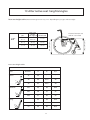
1
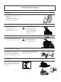
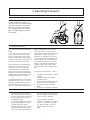
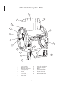
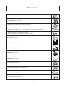
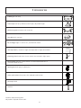
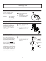
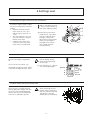
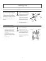
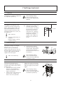
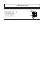
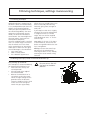
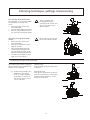
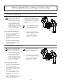
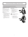
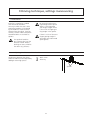
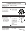
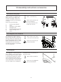
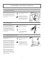
Elite Manual English 74060H2014-06-09 Contents HeadingPage 1.General............................................................................................ 3 2.Handling/Transport.......................................................................... 4-5 3. Product description Elite................................................................... 6 4.Model.............................................................................................. 7 5.Options/Accessories......................................................................... 8-11 6. SettingsSeat............................................................................... 12-15 7. Backrest......................................................................... 16-17 8. Footrests........................................................................ 18 9. Driving technique/Manoeuvring...................................... 19-25 10. Assembly instructions Accessories.................................................... 26-31 11. Care and maintenance..................................................................... 32-33 12. Tests and Guarantees....................................................................... 34 13. Alternative Seat heights/Angles........................................................ 35 14. Weights and Measurements/Standard models.................................. 36 2 1 General The manual must be read thoroughly to avoid damage when handling and using the Elite chair. is a warning triangle to indicate that special care should be taken. (!) Anti-tips provides advice and tips worth considering. a vailable as an accessory. At the correct setting they will prevent the wheelchair from tipping backwards. We recommend all users to use the anti-tip devices, unless you are an experienced user with absolute control over your wheelchair. Elite is a manual, light, rigid frame titanium wheelchair for active users. Elite has a large number of adjustment possibilities and its design is particularly well suited to enable users to easily put it in and out of cars on their own. It has been tested and approved for a user weight of 125 kg, and is intended for use both outdoors and indoors. The seat is adjustable in height, angle and depth. The backrest is adjustable in angle and contour and is cut to the height required. The footrest is adjustable in height and if footrests are selected these are adjustable in height, angle and depth. Elite can be supplemented and adjusted if needs change. A large range of options and accessories are available: Various types of backrest, vertically adjustable push handles, anti-tips, different types of hand rims etc. Elite has the best prerequisites to create comfort, functionality and good manoeuvrability. Crash test Elite (serial no. 10D) is tested in accordance with ISO 7176-19 and ISO 10542. These ISO standards specify requirements for the design of the wheelchair’s restraint points, how the wheelchair and the user are secured in the vehicle, and also describe how tests should be carried out and how the test results should be interpreted. Etac’s wheelchairs are crash tested at the Technical Research Institute of Sweden. The test was carried out with normal settings and with an UNWIN_WWR/ATF/K/R restraining device and an UNWIN_WWR/HD/ATF/K/R 3-point belt. Seat widths: Seat depth: Max. user weight: From 35 cm to 45 cm. Short: 33-39 cm. Long frame: 39-45 cm. With 5" castor wheel, 100 kg. With 6" castor wheel, 125 kg. Elite is supplied with the rear wheels unmounted. Service life: The product is tested and fulfils the demands stated in EN 12183. The main product’s durability and lifetime is at least five years when used in accordance with intended use, the safety instructions, the reconditioning manual and instructions for use in the user manual. The main product consists of the chassis for seat and back support. Additional parts/accessories are handled in accordance with the manual and reconditioning manual. The actual lifetime can vary, depending on how much and how intensively the product is being used, but a maximum of 10 years. Thereafter the product must be decommissioned. The following methods of surface treatment have been used: Lacquered surfaces=Polyester powder coating Non-lacquered aluminium parts=Anodized coating Non-lacquered steel surfaces=Galvanized The tool kit contains: 5 Allen keys: 2, 3, 4, 5 and 6 mm 2 Ring spanners: 10 and 8 mm 1 Socket spanner: 24/19 mm 3 2 Handling/Transport 2:1 Folding • • • Remove any armrests or sideguards. Remove the rear wheels. Fold down the backrest by pulling upwards on the cord. 2:2 Unfolding • • • Attach the rear wheels Fold up the backrest Attach any armrests or sideguards required. When attaching the rear wheels, always check that they are securely mounted. The button in the hub should pop out completely. 2:3 Lifting the wheelchair • Lift by holding the push handles and the front part of the frame. Before lifting, ensure that the push handles are securely fastened. 2:4 Transportation in vehicles Private car/taxi: The wheelchair can be placed in the car boot. If this is not possible, ensure that the wheelchair is placed safely in a seat, so that it cannot overturn or roll. If possible secure the wheelchair with the car’s safety belt. 2:5 Securing The wheelchair must be secured as follows, the straps must not be put through the wheels or around the back tubes. 4 2 Handling/Transport 2:6 Seat belt If the wheelchair is used as a seat for travel, Etac recommends that the user wears the 3-point belt that is fitted in the vehicle. It is important that the 3-point belt is fitted correctly, as in the illustrations. 2:7 Recommendations Etac recommends in the following order: 1) The user transfers to one of the seats in the vehicle and uses the vehicle’s 3-point belt while travelling. The wheelchair is then placed in the boot or safely in the back seat so that it cannot overturn or roll. 2) The wheelchair is secured facing forwards in the vehicle as per this manual, the user uses a separate 3-point belt that is secured in the vehicle. This is the way in which the wheelchair is tested and approved according to the ISO-standard for crash testing of wheelchairs in vehicles. 3) According to directive 2001/85/EC, appendix VII, point 3.8.3. there are specially marked wheelchair locations in vehicles that permit transport with a wheelchair facing in the opposite direction of travel. If this means of travel is used, the user/ carer must be aware while travelling, prepared for sudden movements and have the capacity to maintain a safe sitting position throughout the entire journey. The user’s disabilities must not be of such an extent that he/she is not able to hold onto the handles fitted in the vehicle when there are changes of speed or direction. In conjunction with points 2 and 3: • • • • • a 25668 positioning belt should be used a correctly adjusted headrest should be used the backrest should be level with or above the user’s shoulders the parking brake should be used the anti-tips should be lowered 2:8 Warning • • • The wheelchair’s positioning belt is not sufficient to prevent the user from being thrown out of the wheelchair in the event of sudden braking. The restraining device must not be passed through the wheels or around the back tubes. Options/accessories that can be removed without tools, such as trays, must be removed and se- cured or placed where they cannot fly around inside the vehicle in the event of a collision. • If the wheelchair has been involved in a collision in a motor vehicle, it should be inspected at a Technical Aids Centre or by Etac before being used again. 5 3 Product description Elite 2 3 1 17 16 4 15 14 5 13 11 12 10 7 6 9 8 1 Push handles 10 Front fork attachment 2 Backrest cover 11 Protective stopper 3 Backrest upholstery 12 Brake 4 Seat upholstery 13 Quick release hub 5 Frame14 Wheel mounting 6 Footrest15 Handrim 7 Calf strap 16 Backrest angle plate 8 Castor wheel 17 Rear wheel 9 Front fork 6 4 Model Elite Alternative model (option) Standard model Seat settable in height and angle Seat settable in height and angle Front seat height set at 49 cm Front seat height set at 44-54 cm 5" allround castor wheels 6.5" allround castor wheels, 6" pneumatic Front fork medium with 3 alternative height settings for the castor wheels Front fork short or long with 3 alternative height settings for the castor wheels. Rear seat height set at 45 cm Rear seat height set at 41-49 Seat angle 5° 0-10° backwards tip Seat depth adjustable 5 cm (upholstery folded in) 24" rear wheel, quick release hub 24" rear wheel, quick release hub 1" high pressure tyre (with inner tube) 1 3/8 low pressure or solid tyres Handrims: aluminium Handrims: stainless, titanium, cellular rubber or plastic coated Camber angle 3° Camber angle 0° Backrest settable in angle and shape, foldable Backrest settable in angle and shape, foldable Backrest standard height 40 cm Backrest height cut to 38, 36, 34, 32, 30 cm Backrest height infinitely variable between 35-42 cm Backrest angle in alternative positions +3°, 0°, -5°, -8° and -10° Backrest angle set at -3° Adjustable backrest upholstery in velour and plush Footrest Footrest Footrest height infinitely variable Flip-up footrests, adjustable in height, settable depth and angle Calf strap, adjustable in length Raised footrest, one piece footrest, Sting model for seat widths 35 and 37.5 cm High mounted brakes Brake with long handle and short swing Hub brake 7 5 Options Backrest continuously settable in height 30-45 cm with vertically adjustable push handles A B Brake with long handle and short swing Handrims cellular rubber, aluminium, stainless or plastic coated Raised footrest can be installed 10 cm higher than standard footrest Flip-up footrests settable in angle and adjustable in height Footrest settable in height, angle and depth. Available for 35 cm and 37.5 cm seat width Spiderwheel Settable= Adjusted using tools. Adjustable= Adjusted without tools. 8 5 Accessories Push handle kit removable Push handle height adjustable Armrest height-adjustable short, solid plate, black Armrest cover padded alt. gel., dark grey plush alt. black Dartex, removable Armrest swing-away and settable in height Not in combination with height-adjustable push handles Side guard hard, black Side guard hard, plexi Mudguard folds with the backrest Mudguard right, left Mudguard soft, black Tray mounted on armrest Brake lever extension for standard brakes Seat cushion dark grey plush and black velour, cut according to seat depth set, washable Footplate mounted on footrest 9 5 Accessories Padding for calf strap Heel straps (for flip up footrests) black nylon, adjustable length Positioning belt two-piece with snap lock Seat belt with snap lock Back wedge length 15 and 30 cm, attached with Velcro Anti-tip foldable, settable in height and adjustable in length, detachable Elevating wheel used when the rear wheels are removed in tight spaces Cane holder two parts, one of which is an elasticated section that is fastened around the cane Spoke guard with grey or yellow print Tetra quick release for persons with reduced hand function Castor pin lock Tool kit Settable= Adjusted using tools. Adjustable= Adjusted without tools. 10 5 Accessories Bags front bag backpack mobile holder Leg warmer Proof Information is available at www.etacbutiken.com Rain cape Proof Information is available at www.etacbutiken.com Gloves Information is available at www.etacbutiken.com Weather protector Proof Information is available at www.etacbutiken.com Bags Case Logic Information is available at www.etacbutiken.com Settable= Adjusted using tools. Adjustable= Adjusted without tools. 11 � 6 Settings seat 6:1 Front seat height The front seat height (settable 45-55 cm) is dependent on: Castor wheel 5", 6" or 6.5". Front fork attachment Settable in angle. Front fork Short, medium or long with three alternative heights for the castor wheel. Risk of tipping: Always check the positioning of the anti-tips. (!) See also point 13: “Alternative seat heights/angles”. 6:2 Castor wheel The height may be adjusted by changing the castor wheel itself or by changing its position in the fork. Unscrew the castor wheel and place it at the desired height in the front fork. Tools: 5 mm Allen key and 10 mm U-spanner. (!) Also adjust the angle of the front fork attachment, see point 6:4. 6:3 Changing front fork Unscrew the protective stopper (1) on the front fork attachment to reach the retaining nut (2). Unscrew the nut and pull out the front fork. Take the washer from around the fork axle and put it on the new fork (the bevelled side (A) towards the fork). It is also important to ensure that the washers in the attachment (under the retaining nut) are placed in the right order, with the spring washer (B) on top. Tighten the retaining nut until it cannot be turned any more. Loosen it 1/2-1 turn. The spring washer then has the correct tension. It reduces the risk of the castor wheel starting to “wobble”. Tools: 19 mm socket spanner. (!) Also adjust the angle of the front fork attachment, see point 6:4. 1 2 B Bearings A 12 6 Settings seat 6:4 Setting the angle of the front fork attachment The correct angle setting is important for the wheelchair’s manoeuvrability. • Unscrew the lower attachment screw (A) 1/2-1 turn and the upper screw (B) 1/2 a turn. • Turn the eccentric nut (C) until the attachment is perpendicular to the floor. • Hold the nut in place with a spanner whilst the attachment screws are tightened. Tools: 6 mm Allen key and a 19 mm socket spanner (a spirit level might be useful). B C (!) Keep your eye on something vertical, e.g. a doorpost or a table leg when setting the angle. This adjustment must be made when the seat height is changed at the front or rear in order to retain manoeuvrability. A 6:5 Rear seat height The rear seat height is dependent on: The size of the rear wheel 24" The height setting of the rear wheel 3 alternative height positions: A-B-C Risk of tipping: Always check the positioning of the anti-tips. (!) See also point 13: “Alternative seat heights/angles”. C B A 6:6 Rear wheel with quick release hubs The shaft axle is movable and can also be adjusted in length. Turn the nut on the axle inwards/outwards while at the same time holding the axle with an adjustable spanner. Position When attaching the rear wheels, always check that they are securely mounted. The button in the hub should pop out completely. 13 41 cm 45 cm 48.5 cm 6 Settings seat 6:7 Height adjustment of the rear wheels Unscrew the axle sleeves and washers, tilt the rear axle to free it and mount it at the required height. Mount the rear axle with the large bevelling towards the right wheel attachment. At the same time as the rear seat height is being adjusted you should make sure you have set the correct centre of balance. See point 9:8. Tools: 21 mm socket spanner. Check that the rear wheel is correctly mounted, see point 6:6. Always check the positioning of the anti-tips. Always adjust the brakes after repositioning the rear wheels. (!) Also adjust the angle of the front fork attachment. 6:8 Adjusting the brakes The brakes are infinitely settable. • • • Loosen the screws a few turns and slide the brake until the brake block is about 20 mm from the tyre when the brake is not applied. If the locking bracket comes into contact with the crossbar, move it from position 1 to position 2. Test the brakes. Tools: 5 mm Allen key The braking effect is dependent on the air pressure in the tyres. The brakes are parking brakes and should not be applied during use. Brake lever extensions are available as accessories, see point 10:12. 14 Position 1 Position 2 6 Settings seat 6:9 Seat angle The seat angle is dependent on the difference between the front and the rear seat heights. The seat angle is settable between 0-10° backwards inclination (0-7 cm). Bear in mind the risk of tipping, always adjust the setting of the anti-tips. (!) If the seat angle is changed: -Adjust the angle of the front fork attachment. -Also check the angle of the backrest. (!) The functional seat depth can be up to 6-7 cm longer depending on the settings of the backrest upholstery, see point 7:4. 6:10 Seat depth The seat depth can be adjusted 5 cm by tucking in the front part of the seat upholstery. Short frame: 33-39 cm (measured from the backrest). Long frame: 39-45 cm (measured from the backrest). 15 Seat height rear Seat height front 7 Settings backrest 7:1 Backrest The backrest is settable in angle and has adjustable upholstery. Risk of tipping: Always check the position of the anti-tips after adjusting the backrest. 7:2 Backrest height The height of the backrest is adjustable by cutting the back tubes. When using the push handles the back tubes should be cut 10 mm above the upper attachment hole. Alternative heights: 40, 38, 36, 34, 32 and 30 cm. (!) Tools: Hacksaw (!) Unusual combinations are available: Backrest heights. Contact customer service. When the push handles are attached the back tubes are 3 cm lower. If it should be necessary to extend a backrest which has previously been cut, a backrest extension is available with attachments for push handles. Max. height of a backrest incl. extension is 40 cm. 10 mm 7:3 Backrest angle The backrest angle has fixed positions at +3° 0° -3° -5° -8° -10°. Remove screw (A) completely, loosen screws (B) one turn. Set the desired angle by inserting screw (A) into the angle indicator required. Tighten the screws again. Tools: 4 mm Allen key Fold the backrest down onto the seat whilst adjusting the angle. Allow plenty of room for the backrest cover between the seat and the backrest. Risk of tipping: Always check the positioning of the anti-tips after adjusting the backrest angle. (!) 7:4 Backrest upholstery The shape of the backrest up holstery is individually adjustable by using the four Velcro straps and the backrest cover. • Allow the cover plenty of room between seat and backrest, so that it is possible to “sit in” against the backrest. • Loosen all the straps and ensure that the user is sitting as far back in the seat as possible. • Tighten the straps so that they follow the contours of the back and give support to the lumbar region. Risk of tipping: Always check the positioning of the anti-tips after adjusting the backrest upholstery. 16 B A C 7 Settings backrest 7:5 Backrest continuously settable in height The backrest height is continuously settable from 35 to 42 cm. Loosen the screws (A) 2-3 turns to set the height of the backrest. Ensure that both sides are at the same height by checking against the ruler (B) on the back of the back tube. Tighten the screws securely. (option) Tools: Allen key 5 mm. 17 8 Settings footrests 8:1 Height of the footrest Elite is supplied with a footrest that is settable in height. Height: Loosen the screw (A) on the rear of the footrest attachment on both the right and left sides. Set the footrest at the height required. Tighten securely. Max. height: 9 cm from floor level. Min. height: 4 cm from floor level. 8:2 Flip-up footrests Tools: 6 mm Allen key A raised footrest is available if one is required that is higher than standard. For outdoor use the footrest should be 5 cm above the ground. Never stand on the footrest as there is a risk of tipping! (!) (option) Elite can be supplied with flip-up footrests that are settable in angle and depth. When flip-up footrests are used, the wheelchair must be equipped with a front axle to maintain stability. Angle: Loosen the screws (C) slightly. Set the footrest at the desired position and retighten the screws. Tools: 5 mm Allen key Depth: The sides of the footrests have different lengths. By changing the left side for the right they will extend further forwards. If the depth is altered, the (!) angle must be adjusted. For outdoor use the footrests should be raised 5 cm above the ground. Never stand on the footrests as there is a risk of tipping! 8:3 One-piece footrest (option) Elite can be supplied with a onepiece footrest that can be swung away under the seat. The footrest is settable in height, depth and angle. A support brace is available, which can be fitted between the front frame tubes to provide stability. Tools: 5 mm Allen key For outdoor use the footrest should be raised 5 cm above the ground. Never stand on the footrest as there is a risk of tipping! 18 A 9 Driving technique, settings manoeuvring 9 :1 Driving technique Weight distribution is the decisive factor when it comes to manoeuvrability. It is in part dependent upon the user’s weight, size and seating position and in part upon the position of the rear wheels longitudinally. The more weight that is placed over the rear wheels, the easier the wheelchair is to manoeuvre. The more weight over the castor wheels, the heavier the chair becomes to operate. The Elite standard model is supplied with a 3° camber angle. This means that the wheels are a little closer to the seat/backrest on top and are wider apart at floor level. This gives several advantages. The wheelchair: • turns more easily • holds a steady course • has a broader support base Allows the user to hold his/her arms closer to the body when driving forwards, giving more strength to each push. If you require a chair that is slightly narrower, Elite can be ordered with a straight back axle (0° camber angle). Elite can also be supplied with double back axles - 0° and 3° camber angle. Care giver: If the user is left alone in the wheelchair, ensure that the brakes are applied and that the antitip is swung down. Parking: Increase the overall support base of the wheelchair by reversing for about 10 cm, thereby ensuring the castor wheels swing forwards. 9:2 Driving technique, kerbs and raised thresholds: up User, driving up forwards: This technique is recommended only for experienced wheelchair users. • Ensure that the anti-tips are turned upwards. • Drive forward to the edge of the kerb/threshold. • Balance the wheelchair on its rear wheels so that the castor wheels lift high enough off the ground to clear the obstacle. Grasp the handrims firmly, while at the same time leaning forwards with your upper body. Be sure to turn the antitips back to the down position. 19 9 Driving technique, settings manoeuvring Care giver, driving up forwards: • Ensure that the anti-tips are turned upwards. • Tilt the wheelchair, if necessary with help from the tilter, so that the castor wheels come up on the pavement. • Lift by the push handles to help the rear wheels up. Be sure to turn the anti-tips back to the down position. User, driving up backwards: This technique only works if there is a low kerb/threshold, relative to the installed height of the footrests. • Ensure that the anti-tips are turned upwards. • Reverse to the edge of the kerb/ threshold. • Take a firm hold of the handrims while at the same time leaning forwards. Be sure to turn the anti-tips back to the down position. Care giver, driving up backwards: • Reverse the chair to the edge of the kerb/threshold. • Tilt the wheelchair up, if necessary with help from the tilter, so that the castor wheels are in the air. • Pull the wheelchair upwards and backwards, ensuring that the castor wheels have cleared the edge before setting down the wheel chair onto all four wheels. Be sure to turn the anti-tips back to the down position. 9:3 Driving technique kerb: down User, driving down forwards: This technique is recommended only for experienced wheelchair users. • Ensure that the anti-tips are turned upwards. • Drive forward to the edge of the kerb. Care giver, driving down forwards: • Ensure that the anti-tips are turned upwards. • Tilt the wheelchair up, if necessary with help from the tilter, so that the castor wheels are in the air. • Drive carefully down the kerb and set down the castor wheels onto the ground again. • Take a firm hold on the handrims and drive “straight out” so that the wheelchair lands below the kerb on all four wheels simultaneously. Be sure to turn the anti-tips back to the down position. Be sure to turn the anti-tips back to the down position. 20 9 Driving technique, settings manoeuvring User, driving down backwards: This technique is not recommended for differences in level of over 10 cm. • Ensure that the anti-tips are turned upwards. • Reverse to the edge of the kerb. • Reverse carefully down while at the same time leaning forwards. There is a greater risk of tipping during this manoeuvre. Be sure to turn the anti-tips back to the down position. Be sure to turn the anti-tips back to the down position. Care giver, driving down backwards: • Ensure that the anti-tips are turned upwards. • Reverse the wheelchair to the edge of the kerb. • Drive carefully down the kerb and reverse the wheelchair on the rear wheels until the castor wheels have cleared the obstacle. • Set down the wheelchair once again on all four wheels. 9:4 Driving technique inclined surface The following constitutes important advice for driving up or downhill to avoid the risk of tipping. (!) Avoid turning round in the middle of a hill. Always drive as straight up/down as possible. It is better to ask for help than to take a risk on your own. Uphill driving: Lean forwards to correct your centre of balance. Downhill driving: Lean against the backrest to correct your centre of balance. Control your speed using the handrims, not by means of the brakes! 21 9 Driving technique, settings manoeuvring 9:5 Driving technique stairs: up Always ask for help. Never use an escalator, even if a care giver is available. We always recommend using two carers for this transfer. One who walks behind and holds on to the push handle and one who walks in front and holds on to the frame (or in the legrests if these are lockable). • When the last step has been cleared, continue backwards so that the castor wheels are over the ground before setting down the wheelchair onto all four wheels. Be sure to turn the anti-tips back to the down position after completed transfer. With care giver, backwards: • Turn the anti-tips upwards and ensure that the push handles are securely tightened. • Reverse the wheelchair to the first step. • Tilt the wheelchair onto its rear wheels. • Pull the wheelchair slowly up, one step at a time, keeping the chair balanced on its rear wheels at all times. (!) The care givers should remember to use the strength in their legs and to keep their backs as straight as possible while lifting. 9:6 Driving technique stairs: down Always ask for help. Never use an escalator, even if a care giver is available. We always recommend using two carers for this transfer. One who walks behind and holds on to the push handle and one who walks in front and holds on to the frame (or in the legrests if these are lockable). Be sure to turn the anti-tips back to the down position after completed transfer. (!) The care givers should remember to use the strength in their legs and to keep their backs as straight as possible while lifting. With care giver, forwards: • Turn the anti-tips upwards and ensure that the push handles are securely tightened. • Drive forward to the first step and tilt the wheelchair onto its rear wheels. • Drive carefully down, one step at a time, keeping the chair balanced on its rear wheels at all times. • After clearing the last step, “set down” the wheelchair once again on all four wheels. 22 9 Driving technique, settings manoeuvring 9:7 Manoeuvring, transferring into/out of the wheelchair The technique for transferring a user should be practised with trained personnel. All that is provided here is some important advice to consider in conjunction with transferring a user into or out of the wheelchair. With or without a care giver, sideways. Before transferring: • Reverse the wheelchair 5-10 cm before stopping so that the castor wheels are turned forwards. • The wheelchair should be placed as close to where the transfer is going to take place as possible. • Apply the brakes, remove the armrest/sideguard on the side where the transfer is to take place. With or without a care giver, from the front: Before transferring: • Reverse the wheelchair 5-10 cm so that the castor wheels are turned forwards. • The wheelchair should be placed close to where the transfer is going to take place. • Apply the brakes. Never stand on the footrest or the footrests as there is a risk of tipping! (!) The care givers should remember to use the strength in their legs and to keep their backs as straight as possible while lifting. 23 9 Driving technique, settings manoeuvring 9:8 Adjusting the centre of balance The centre of balance can be adjusted by changing the position of the rear wheels. • (!) Remove the hub casing and its washers and move the back axle forwards or backwards as per point 6:7. Also adjust the brakes, see point 6:8. The centre of balance is also altered when the seat and/or backrest angle is adjusted. The use of anti-tips is recommended. Check carefully that the rear wheels are securely mounted, see point 6:6. Tools: 21 mm socket spanner When the position of the rear wheels is moved forwards the wheelchair becomes easier to drive and turn, but the tendency to tip backwards increases. 9:9 Changing the camber angle (option) The rear wheels are mounted with a standard 3º camber angle. The camber angle can be changed to 0° by replacing the back axle and the washers that sit between the hub casing and the wheel mounting. Tools: 21 mm socket spanner. (!) The marker on a 0° camber washer is mounted pointing upwards. 24 9 Driving technique, settings manoeuvring 9:10 Handrims Etac Elite is supplied as standard with aluminium handrims. The way in which the user is able to grip the handrims is influenced by the handrim’s material and its distance from the wheel. Titanium, stainless, cellular rubber and plasticcoated handrims are available as options. The optional handrims give a better grip, but also increase friction. Violent braking can cause mild friction burns (e.g. blisters). Be aware that when passing through narrow spaces there is a risk of getting your fingers caught. There is also a risk of fingers getting caught in the spokes. If there is a risk of the user’s fingers getting caught in the spokes we recommend spoke guards. 9:11 Adjusting the distance of the handrim The distance between the wheel and the handrim can be adjusted by adding or removing spacers. Tools: 4 mm Allen key. Spacers 25 10 Assembly instructions accessories Assembly instructions are always provided with accessories when they are supplied by Etac. Instructions are also available on our website www.etac.com 10:1 Seat cushion The cushion is cut to the required depth at the front or back edge. When measuring the length, ensure that the cushion is properly positioned between the back tubes with the rounded corners to the rear. The cushion is a standard model and is not suitable for users with sitting sores. 10:2 Armrest, detachable, height adjustment The detachable armrest is available with a short armrest guard. The armrest is vertically settable between 19-26 cm with 1 cm intervals. • Fully loosen the screw on the side guard. It secures the locking lug for height adjustment. • Slide the sideguard up or down to the desired height. • Refasten the lug on the side guard. Tools: 3 mm Allen key. (!) The locking lug is used both to set the height of the armrest and secure the side guard: If the height of the side guard is to be moved along with the height of the armrest, an extra locking lug and screw can be ordered. There are separate instructions for fitting the armrest attachment. Never use the armrests to lift the wheelchair. 10:3 Padded cover, armrest The detachable armrest can be supplemented with a padded or gel cover. The covers are manufactured in dark grey plush, or alternatively black Dartex, and they are washable. (!) The cover makes the armrest 1.5 - 2 cm higher. 26 10 Assembly instructions accessories 10:4 Armrest, swing away Height settable in 3 different positions: 19 cm, 23 cm and 27 cm. To adjust the height: Loosen the screw (2). Remove the locking pins (3 and 4). Move to the desired height. 1) Armrest tube right/left 2)Screw 3) Locking pin (unthreaded) 4) Locking pin M5 5) Armrest attachment fitting 6) Push handle grip cover 7)Screw Tools: 5 mm Allen key 6 Never use the armrests to lift the wheelchair. Anti-tips cannot be combined with armrest. Tools: Phillips screw driver, 5 mm and 3 mm Allen keys. Never use the armrests to lift the wheelchair. 10:6 Mudguard The mudguard is made of polyester and is fitted by means of two screws in the back tube. First make a hole in the backrest upholstery using an awl or something similar. Ensure that the hole you make corresponds to the drilled hole in the back tube. The front edge of the mudguard is 2 3 4 5 7 10:5 Sideguard, hard, transparent The sideguard is made of polycarbonate and mounted on the wheelchair by means of a clamp that can be fixed to the back tube. The sideguard is designed so that it is easily removable from the wheelchair. Assembly instructions are provided with the sideguards. 7 1 attached to the seat upholstery using Velcro straps. Tools: Phillips screwdriver Never use the mudguards to lift the wheelchair. 27 10 Assembly instructions accessories 10:7 Mudguard, foldable with the backrest The mudguard is made of transparent polycarbonate and need not be detached when the backrest is folded down. The mudguard is fixed by a screw on the back tube and a screw on the seat frame. Tools: 3 mm and 4 mm Allen key Never use the armrests to lift the wheelchair. 10:8 Anti-tip, mounting The anti-tip consists of several parts: • • • The attachment bar is mounted under the wheel-mount (see illustration). The anti-tip bar snaps onto the attachment bar at the required length. The extension with the stabiliser wheel is fixed to the anti-tip bar by means of a screw and nut at the desired height. To enable thresholds and the edges of thick carpets to be negotiated, a distance of 3-5 cm from floor level is recommended. Tools: 4 mm Allen key, 8 mm spanner. 2 x 5 mm Allen keys for affixing to chassis. (!) The extended extra anti-tip bar is recommended when the rear wheels are mounted in position A. After adjusting the seat height, centre of balance or backrest angle, always ensure that you check the positioning and function of the anti-tip. A special anti-tip with a shorter antitip bar is available for Elite with 20" wheels mounted in position C. 28 10 Assembly instructions accessories 10:9 Belt The belt is adjustable in length and has a snap-lock. Assembly instructions are supplied with the belt. (!) The seat belt is to be used only for positioning in the wheelchair. It must not be used as a substitute for a car safety belt. Ensure that the user does not slide forwards in the seat as this can lead to blood circulation being impaired in the midriff region. The belt can be secured in one of the two holes in front of the backrest joint. 10:10 Heel strap for flip-up footrests The heel strap is mounted on flip-up footrests. It can be adjusted lengthwise. Hole instructions for fitting the screw are on the bottom of the footrest. The front or back “corner” can be used. Make the hole by carefully knocking the screw through the plate, e.g. with a hammer. Assembly instructions are supplied with the heel strap. Tools: 10 mm spanner. (!) Adjust the length so that the foot is placed in the centre of the footrest and does not come into contact with the castor wheels. 29 10 Assembly instructions accessories 10:11 Brake lever extension The brake lever extension can be fitted to a standard brake. Remove the rubber hand grip. Attach the extension arm by means of the 2 screws. Place the rubber hand grip onto the extension arm. Tools: 4 mm Allen key and 8 mm spanner. The braking effect is dependent on the air pressure in the tyres. The brakes are parking brakes and should not be applied during use. 10:12 Push handle kit The push handle attachments are mounted in the predrilled holes in the back tubes by means of two screws. The push handle attachments extend the backrest height by 3 cm. The push handles are screwed into the attachments after the upholstery has been fitted. Check and re-tighten the screws after one week of use. Tools: 4 mm Allen key. (!) Push handle attachments are also available in two longer versions. 10:13 Height adjustable push handles The push handles can be set at intervals of 5 cm. Remove the backrest upholstery, fix the smaller of the fixing lugs to the back tubes. Mount the upper push handle attachment onto the back tubes and replace the upholstery. Fix the attachment tube for the vertically adjustable push handles into the upper attachments. Mount the larger fixing lugs onto the tubes. Secure by means of the screws and nuts. Fix together the two attachment tubes in the middle. Tighten all screws. Loosen the knob on the attachment tube and install the required height for the push handles. Tighten the knobs. Tools: 4 mm, 5 mm, 6 mm Allen key and 10 mm spanner. Ensure that the knobs are securely tightened. This is especially important if you intend to lift the wheelchair whilst the user is sitting in it. 30 Attachment 10 Assembly instructions accessories 10:14 Spoke guards The spoke guards prevent your fingers from becoming entangled in the spokes and also give some protection against splashing. Assembly instructions are provided with the spoke guards. 10:15 Tetra quick-release adapter The adapter makes it possible for users with reduced hand/finger strength to use the quick release system. They can also be useful for helpers who have to frequently remove/replace the wheels. Assembly instructions are provided with the tetra quick release adapter. Tools: 8 mm spanner and screwdriver. When the wheel is in position the adapter should be pushed to one side and fastened with its hook to a spoke. When attaching the rear wheels, always check that they are securely mounted. The button in the hub should pop out completely. 31 11 Care and maintenance Upholstery The upholstery is made of two-ply polyester or coated fabric. The seat upholstery is secured by means of straps around the seat frame. The upholstery can easily be removed from the chassis frame by loosening the straps under the seat. The backrest upholstery is removed by loosening the cover, detaching the elastic band and any accessories and then pulling the upholstery upwards. Wash seat and backrest upholstery according to the washing instruction. Rear wheel, castor wheel, front fork attachment Handrims:If a handrim should be damaged in such a way that it could lead to hand injury, it should be replaced. Front fork attachment:To achieve the best driving technique, the attachments should be installed at 90°. Also check that the front forks are tightened according to instructions, see point 6.3. Tyre/inner tube:Check the tyre pressure (see side of tyre) at least once a month; also check the tread. Spokes: Loose spokes can lead to wheel wobble. Consult a cycle dealer or your Technical Aids Centre if it is necessary to adjust the spokes. Wheel axles: Clean the wheel axles from hair and dirt as necessary. Ball bearings: Require no maintenance. Brakes brakes once a month. The braking effect is dependent on the air pressure in the tyres. Encrusted dirt can have a negative effect on the brake mechanism. Check the functioning of the In the event of adjustments, see point 6.8. Washing the frame is easy to wash and dry. Clean the frame with a nonabrasive cleaning agent with a pH level between 5 and 9, or with a 70% disinfectant solution. Rinse and dry. It is important to keep the wheelchair clean, both for your own comfort and the longevity of the chair. It is equipped with drainage holes which ensures that it Touch-up paint Touch-up paint is available for minor scratches and chips in all the frame colours available for Etac wheelchairs. Other If there is a fault in your wheelchair you should contact your prescriber or Technical Aids Centre. Defective wheelchairs should not be used. If your chair needs reconditioning or repair, only original parts from Etac or components with equal quality, as specified in Elite diagrams, should be used. Etac will not be held responsible for damage or injury caused by use of nonoriginal parts. (!) 32 When necessary lubricate moving parts/joints with bicycle oil or similar. 11 Care and maintenance Fault-finding chart Problem* The wheelchair pulls to the side Solution • • • • • • Inflate the tyres Adjust the front fork attachment’s angular setting Check that the front fork attachments are mounted at the same height Rear wheel mountings are incorrectly fitted The user is distributing weight unevenly More strength being used on one side than the other when propelling the chair The wheelchair feels “heavy” to manoeuvre • • • • Inflate the tyres Rear wheel mountings are incorrectly fitted Clean the castor axles from hair and dirt Too much weight over the castor wheels. Adjust the centre of balance The wheelchair feels “heavy” to turn • • • • • Inflate the tyres Check that the front forks are not too tight Adjust the front fork attachment’s angular setting Clean the castor axles from hair and dirt Too much weight over the castor wheels. Adjust the centre of balance Brakes not effective • • Inflate the tyres Adjust the distance between brake and tyre Rear wheels “loose” • Adjust the length of the axle shaft The rear wheels are hard to remove/replace • • Clean and lubricate quick release with cycle oil or similar Adjust the length of the axle shaft The castor wheels “wobble” • • The front forks are not tight enough Check that the front fork attachments are mounted at the same height Adjust the front fork attachment’s angular setting Too much weight over the castor wheels. Adjust the centre of balance • • The wheelchair feels “awkward” • • Inflate the tyres Check that screws, nuts and bolts are properly tightened * The user may experience several of these problems if the wheelchair is incorrectly adjusted or is being incorrectly used. (!) When necessary, lubricate moving parts/joints with bicycle oil or similar. 33 12 Tests and guarantees Elite is tested and approved for use indoors and outside and is CE marked. Max. user weight is 125 kg. The Swedish Institute of Assistive Technology accredited for tests. carries out both functional and technical tests. Its test methods conform to ISO 7176 and EN 12183. CE marking:The product has passed all tests and met all criteria set by European standards for specific product groups. A proof that the product meets national and EU MDD (Medical Device Directive) requirements. Gives customers the chance to choose the right product by comparing test data. Guarantee: 5 year guarantee against material and manufacturing defects. For terms and conditions, see www.etac.com Special adaptationscomprise everything that falls outside the instructions and settings in this Manual. Wheelchairs specially adapted by customers are not eligible for Etac’s CE marking. Etac’s guarantee no longer applies. If in doubt about adaptations, consult Etac. Combining Elite with other products, not manufactured by Etac: In general neither of the products will retain their CE marking. Etac has agreements with a number of firms whose products are approved in combination with Elite, including seat systems and motors. These can be combined and still retain their CE certificates from the manufacturers. Contact Etac for up-to-date information. 34 13 Alternative seat heights/angles Rear seat height table (Measurements given can vary ± 2% depending on tyre type and seat angle). Rear seat Distance rear Rear wheel height pos. Seat angle 3° wheel-seat 48.5 cm 11 cm B 1-4 45 cm 15 cm C 1-4 41 cm 19 cm Seat height rear A 1-3 C B A 4321 Front seat height table Castor wheel Fork Short 1 2 3 Medium 1 2 3 Long 1 2 3 Position 5" 6" 6,5" S1 44 - - S2 46 47.5 48 S3 47 48.5 49 M1 49 50 50.5 M2 50 51 52 M3 51 52 53 L1 53 54 54.5 L2 54 55 55.5 L3 55 56 56.5 35 Seat height front 24" Distance between seat and 24" rear wheel 14 Weights and dimensions, standard models Type of chair Art. no. Seat depth from back tubes Transport Weight standard width model, withexcl. out rear wheels wheels Seat height front without cushion Seat height rear without cushion Backrest height Total width 35 cm short 13100101- 33-39 cm 45-55 cm 41-49 cm 30-40 cm 57 cm 46.5 cm 5.5 kg 35 cm long 13100102- 39-45 cm 45-55 cm 41-49 cm 30-40 cm 57 cm 46.5 cm 5.5 kg 37.5 cm short 13100103- 33-39 cm 45-55 cm 41-49 cm 30-40 cm 59.5 cm 49 cm 5.5 kg 37.5 cm long 13100104- 39-45 cm 45-55 cm 41-49 cm 30-40 cm 59.5 cm 49 cm 5.5 kg 40 cm short 13100105- 33-39 cm 45-55 cm 41-49 cm 30-40 cm 62 cm 51.5 cm 5.6 kg 40 cm long 13100106- 39-45 cm 45-55 cm 41-49 cm 30-40 cm 62 cm 51.5 cm 5.6 kg 42.5 cm short 13100107- 33-39 cm 45-55 cm 41-49 cm 30-40 cm 64.5 cm 54 cm 5.6 kg 42.5 cm long 13100108- 39-45 cm 45-55 cm 41-49 cm 30-40 cm 64.5 cm 54 cm 5.6 kg 45 cm short 13100109- 33-39 cm 45-55 cm 41-49 cm 30-40 cm 67 cm 56.5 cm 5.7 kg 45 cm long 13100110- 39-45 cm 45-55 cm 41-49 cm 30-40 cm 67 cm 56.5 cm 5.7 kg Choice of frame colours: 01= black, 02= red, 22= grey texture, 30= blue texture, 33= sea green texture, 34= plum texture, 37= blue chrome/black blaster, 38= black graphite/gold, 43= ruby red, 44= emerald-green, 45= midnight blue, 47= matt blaster 36 Etac Sverige AB Box 203 334 24 Anderstorp Sweden Tel 0371-58 73 00 Fax 0371-58 73 90 info@etac.se www.etac.se Etac GmbH Bahnhofstraße 131, 45770 Marl, Germany Tel 02365-98710 Fax 02365-986115 info@etac.de www.etac.de Etac AB (export) Box 203 334 24 Anderstorp Sweden Tel 46 371-58 73 30 Fax 46 371-58 73 90 info@etac.se www.etac.com Etac Holland BV Fluorietweg 16a, 1812RR Alkmaar, Nederland Tel +31 72 547 04 39 Fax +31 72 547 13 05 info.holland@etac.com www.etac.com Etac AS Pb 249, 1501 Moss, Norway Tel 815 69 469 Fax 69 27 09 11 hovedkontor.norge@etac.com www.etac.no Etac UK Limited 29 Murrell Green Business Park London Road, Hook, Hampshire RG27 9GR, United Kingdom Tel 01256 767 181 Fax 01256 768 887 info@etacuk.com www.etac.com Etac A/S Egeskovvej 12 8700 Horsens Denmark Tel 79 68 58 33 Fax 75 68 58 40 info@etac.dk www.etac.dk Tel 0121 561 2222 Fax 0121 559 5437 enquiries@etac.uk.r82.com www.etac.com Snug Seat, Inc. 12801 E. Independence Boulevard P.O. Box 1739 Matthews, NC 28106, USA Tel 800 336 7684 Fax 704 882 0751 Information@snugseat.com www.etac.com R82 UK Limited. Unit D4A, Coombswood Business Park East Coombswood Way, Halesowen West Midlands B62 8BH United Kingdom Etac Supply Center AB Långgatan 12 SE-334 24 Anderstorp