1
FORBES MARSHALL
1.
ABOUT THE PRODUCT:
a
General Description:
This Valve Mounted pressure controller is a yet solid one for direct
mounting to the control valve and direct impulse connection for
various pressures including vacuum and absolute pressures.
It has the following outstanding characteristics:
1.
2.
3.
Separate interchangeable measuring units.
In-built supply air restrictor and output damping
throttle.
Reversal of action without additional parts.
76
USER’S MANUAL
FORBES MARSHALL
77
USER’S MANUAL
FORBES MARSHALL
b
Specifications:
Measuring Range
: 0.02 To 400 Bar
Absolute Pressure
: 0.05 To 3 Bar
Vacuum
: 0-1 Bar Low Pressure
Supply Air Pressure
: 1.4 Bar
Control Pressure
: 0.2-1 Bar
Set Point/Actual Value
: See Fig. No. B
Speed Of Response Range
: <0.02% Of Medium Set Point
Reversal Range
Point
: <0.033% Of Medium. Set
Hysterisis Range
: <1.1% Of Medium Set Point
Dependence On Supply Pressure : <0.4% Per 0.1 Bar
Air Consumption
: 300 NL/hr
On Y=0.6, Z=1.4,
Nozzle=Dia. 0.2
Valve Speed
: 40 Sec. Up/ 5 Sec Down
Nozzle 2, Actuator UI-30
140 Sec Up/20 Sec Down
Nozzle 2, Actuator UIII-60.
78
USER’S MANUAL
FORBES MARSHALL
79
USER’S MANUAL
FORBES MARSHALL
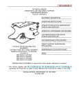
c
Operation:
Ref. Fig.
The pressure to be controlled, ‘x’, which is acting on the
measuring unit (bellows, diaphragm, etc.) is compared to a
set point spring, ‘w’. Any deviation in ‘x’ alters the valve
diaphragm pressure ‘y’ at the nozzle, altering the flow to
the actuator and thereby the lift. This alteration in lift is fed
back to the controller via the adjustable spring ‘R’.
80
USER’S MANUAL
FORBES MARSHALL
2.
GETTING STARTED:
a.
Installation:
The pressure control valve should be stored in its
original packing until it is mounted. The storage
area must be dry and clean. After mounting the
valve should be supplied with control air, this is
best protection against fouling and corrosion.
The protection caps of the valve openings, of the
filter and regulating valve and of the pressure
controller have to be taken off. If there are
conservatives in the spindle area of the valve,
they have to be removed carefully.
The diaphragm control valve is mounted vertically
standing up with actuator on top. The mounting
place has to be easily accessible. Maximum
allowable temperature is 80 degrees centigrade.
The impulse connection is taken at about 1-2 m
after the control valve. The point of pressure
taking has to be provided with a stop valve, so
that in case of troubles you can get the measuring
system free of pressure. Pressure tapping from a
vertical line where the point of tapping is above
the measuring chamber is ideal. In this case the
measuring line can remain filled, and the
possibility of air inclusion cam be eliminated. With
viscous media the tapping point has to be
provided with a separating vessel as to avoid
delays in pressure transmission.
The separating vessel should be mounted as
near as possible to the tapping point.
81
USER’S MANUAL
FORBES MARSHALL
b. Mounting Instruction For Pressure
Controller
Before connecting the air supply to the air filter
and regulator, the newly laid airline should be
carefully blown out to line and it should be
examined for any possible leakages.
82
USER’S MANUAL
FORBES MARSHALL
83
USER’S MANUAL
FORBES MARSHALL
84
USER’S MANUAL
FORBES MARSHALL
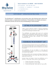
c.
Pressure Controller Part List :
85
USER’S MANUAL
FORBES MARSHALL
d.
Commissioning The Product:
Ref. Fig. G:
On start up the required air-supply is adjusted, at the AFR. The
supply pressure should be about 0.5 bar higher than the maximum
operating pressure of the connected control actuator. (See
nameplate: CONTROL RANGE). The air is checked for moisture,
dirt, etc. by operating the drain valve.
The set-point spring (30) is relieved (-) by turning the nut anticlockwise direction. The operating pressure Y now increases up to
maximum value and control valve closes. The Control Valve can,
now be started as follows.
Open the impulse valve slowly de-aerating the measuring
chamber.
Tighten slowly the Set-point spring (+) until the valve begins to
open. Set the spring tension to the desired set pressure.
If controller oscillates, the measuring chamber must be de-aerated
again. If this does not improve the situation, the proportional range
has to be enlarged by feedback-spring (21).
If the controller remains unsteady, screwing in the damping throttle
can damp the control pressure Y to the Diaphragm chamber. (16)
After start up the following service has to be done. Examine if
hand-wheel is in end position and secured by lock pin. Slightly
tighten stuffing box nut to avoid leakage of media. Tighten all nuts
on valve.
86
USER’S MANUAL
FORBES MARSHALL
87
USER’S MANUAL
FORBES MARSHALL
3.
OPERATION AND MAINTENANCE:
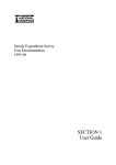
a.
Basic Functions:
PRESSURE REDUCING CONTROLLER:
The FM valve pressure reducing controller works as a pressurereducing valve. If the set pressure value is surpassed, the control
valve closes and reduces the pressure. Air is supplied at pressure
Z which is to be free from dust, oil and water of at-least 4 Bar. The
supply pr. to Roboter. Z1 is adjusted on the Air Filter Regulator (1).
The supply air reaches the nozzle flapper system through the
constant restrictor (18). The flapper (25) at the nozzle lever (26)
covers the nozzle (9) more or less depending upon the pressure
deviation at the bellows (35). This in turn changes the control
pressure y supplied to the actuator. The air supply is limited to a
fixed value by the fixed throttle (18) so that with open nozzle, the
pressure goes towards zero and the actuator can assume the failsafe position as determined by the spring. (In the given fig.
Actuator is mounted in air to close position) At the outer end of the
lever (26), an adjustable feedback spring (21) is connected. By
blocking some spring threads, the feedback force can be changed
depending on the lift position of the control valve. If the feedback
spring is tightened, the proportional range is widened and the
control loop is attenuated. If the feedback spring is loosened, the
proportional range is shortened and the control loop reacts more
sensitively and may even tend to vibrate. The output signal y can
be dampened by a damping throttle (16). The set-point spring (30)
secures the lever (26) in its bearing and counteracts the force on
the impulse pressure, X, at the measuring system. The bellows
assembly consists of the below (35) and the thrust bolt (29).
Depending on the impulse pressure X at the bellow (35), the
distance between nozzle and flapper is changed and thereby the
control pressure Y.
Referring to Fig H, when impulse pressure increases the lever
moves upwards, nozzle closes, control pressure increases and
valve closes. On decreasing impulse pressure X, the lever moves
down, nozzle opens, control pressure decreases and valve opens.
The set value of the spring W can be adjusted by a nut (33) by
tightening & releasing the spring tension (30) .On the cover this
tightening or loosening is marked as "+" or "-" respectively. If set88
USER’S MANUAL
FORBES MARSHALL
point spring is tightened (+) control pressure Y decreases, set
value W increases. If set point spring is loosened (-), control
pressure increases, set value W decreases. The air supply is
limited to a fixed value by the constant fixed throttle (18) so that; it
opens nozzle the pressure goes towards zero and the actuator can
assume the fail-safe position as determined by the spring. (In the
given fig. The Actuator is mounted in air to close position). At the
outer end of the lever (26) an adjustable feedback spring (21) is
connected. By blocking some spring threads, the feedback force
can be changed depending on the lift position of the control valve.
If the feedback spring is tightened, the proportional range is
widened and the control loop
Is attenuated. If the feedback spring is loosened, the proportional
range is shortened and the control loop reacts more sensitively
and may even tend to vibrate. The output signal V can be
dampened by a damping throttle. (16).
2.2 The set-point spring (30) secures the lever (26) in its bearing
and counteracts the force on the impulse pressure, X, at the
measuring system. The bellow assembly consists of the bellow
(35) and the thrust bolt (29). Depending on the impulse pressure X
at the bellow (35), the distance between nozzle and flapper is
changed and thereby the control pressure V.
Referring to Fig. No. 1, when impulse pressure increases the lever
upward, nozzle opens, control pressure decreases and valve
opens.
The set value of the spring W can be adjusted by a nut (33) by
tightening or releasing the spring tension (3.0) On the cover this
tightening & loosening is marked as "+" respectively. If set-point
spring is tightened (+) control pressure y decreases, set value W
increases. lf set-point spring is loosened
(-), control pressure increases, set value W decreases.
89
USER’S MANUAL
FORBES MARSHALL
4.
TROUBLE SHOOTING:
In case there is trouble in starting, the valve can be operated in
any position by means of the hand-wheel It is to be noted that after
manual operation, the hand-wheel should always be set back into
end position and locked by means of a lock pin. In case of Viscous
media the application of a separating vessel is necessary, the
installation should be arranged as showing Fig numbers' (a) & (b).
The lines have to be, arranged with a slope of 1: 10 so that the
enclosed air bubbles can go up to the de-aeration points. Before
start-up the impulse lines, controller and separating vessel should
be carefully filled with a separating, liquid (e.g. Barium Chloride or
Glycerin) .It has to be observed that the least possible air enters
into the system. Then the valve is to be carefully opened. The
media exerts pressure on the separating liquid in the separating
vessel and the system is once more de-aerated. This is very
important as the air bubbles rise in the measuring system and
cause oscillation.
Q1] How to change springs and bellows?
Remove the cover [6] by unscrewing the M5x10L screws
[2](4 noose).
Unscrew the hex-nut [33].
Take-out the bearing [32].
Take-out the spring [30] and spring-plate attached to it
[28]. Turn the notches using Plyer; ensure that the
notches are not damaged. Now take out the spring and
replace with new.
For bellow: 3.5] remove the cover [6] by unscrewing the
M5x10L screws [2](4 nos.).
Unscrew the Allen-bolt (M8x35) [20] 4nos. Remove the
bellow chamber assembly [37].
Replace bellow with new one.
Fix the new bellow by tightening Allen-bolt
(M8x35) [20].
90
USER’S MANUAL
FORBES MARSHALL
Q2] How to adjust Roboter settings for given valve
lift?
Check what is the set pressure of valve – check the
action of Roboter. Suppose the valve is 80#150.
Observe on the VDS. The set pressure and the action of
Roboter are given on it. Suppose the action is reverse
acting down stream control and set pressure is 4.5 bar.
Also check spring and bellow size as per the VDS.
Remove the cover [6] by unscrewing the M5x10L
screws [2](4 nos.). Take out the ball bearing [32], hex nut
[31], set point spring [30].
Polish the flapper [25] with smooth polish paper and
needle file and hit the contact screw [29] by soft headed
mallet/hammer to make the nozzle [9] impression on
flapper [25]. Check for impression. If not there, on the
flapper r then repeat above steps.
Give air supply to AFR. Adjust the pressure of the air
between (3-3.5 bar). Rotate the hex nut [31] in clockwise
direction so that the valve opens fully [i.e. 30 mm for
given valve. Check the pipeline for air leakage by
spraying soap solution near all the joints. There must not
be any leakage. Rotate the hex nut [31] in anti-clockwise
direction until the valve is 50% open i.e. 15mm. Check
the double arm lever [ ] to be horizontal. If not then by
rotating the adjustment lever [ ] make the double arm
lever horizontal. Rotate the contact screw [29] making it
touch the bellow [44]. Again, rotate it 1 ½ [1.5 mm]
rotation of contact screw. Now the valve should be
completely close. [If not the Roboter is to be replaced
completely.] Apply set pressure 4.5 bar through siphon. If
siphon is not used then bellow might get burst. To check
the bellow chamber is completely filled observe the
flowing medium coming out at the air vent port. Now tight
the air vent screw [39].
Rotate the hex nut [33] up to 50 % opening of the valve.
Increase the set pressure 4.5 bar till the valve is fully
closed. Ensure output pressure [p1] on the gauge [13] to
91
USER’S MANUAL
FORBES MARSHALL
be zero or less than operating control range of valve.
Note that pressure. Then decrease the pressure [p2]
bellow 4.5 bar. Do it until the valve gets open fully. Apply
set pressure 4.5 bar and ensure the valve is 50% open.
To check smooth operation of the valve we should check
the proportionate band. {= (P1-p2)/(set pr. X 100)} this
formula should give result between 10 % to 40 %.
Q3] How to change the nozzle?
Remove the cover [6] by unscrewing the M5x10L screws
[2](4 nos.).
Unscrew the hex-nut [33].
Take-out the bearing [32].
Take-out the spring [30] and spring-plate
attached to it [28].
Remove the flapper lever [26]. Unscrew the (m4x40)
screw 2nos. [7]. Take out the traverse [12] and traverse
head assembly [8]. Unscrew the nozzle [9] and replace
with news.
Assemble in reverse as above steps.
Recalibrate.
92
USER’S MANUAL