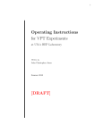
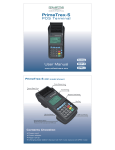
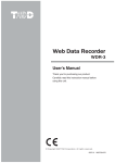
1
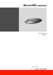
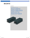
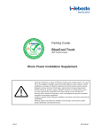
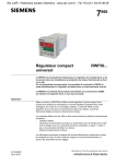
Since 1964, the leader in effective, safe and reliable products for fisheries conservation.
Knowledgeable biologists depend upon Smith-Root equipment.
USER’S MANUAL
BP-1.5 POW PULSER
SMITH-ROOT, INC.
Products for Fisheries Conservation
WWW.SMITH-ROOT.COM
USER’S MANUAL
Contents
Introduction................................................... 1
The BP-1.5-POW Pulsers............................... 2
Control Network............................................ 3
Supported Waveforms................................... 3
Front Panel.................................................... 4
Back Panel..................................................... 4
Version 2.0 POW Barrier Pulsers.................... 7
Restoring Barrier Operation........................... 8
Installation..................................................... 8
Specifications................................................. 9
Items manufactured by companies other than Smith-Root carry the original manufacturer’s warranty. Please contact
product manufacturer for return instructions.
All Smith-Root, Inc. manufactured products are covered by a one year warranty.
Credit & Refund Policy: Customers returning equipment, in new condition, will be given credit to the applicable VISA/Master Card account within five
days from the date of the return. A return authorization must accompany returns. Valid equipment returns include, but are not limited to, ordering incorrect
equipment, funding deficits, and defective equipment returned for reimbursement. All returns are subject to a restocking fee and applicable shipping charges.
The restocking fee is figured at 10% of the purchase price but not less than $20.00. Customers receiving equipment in damaged condition will be referred
to the shipping company for insurance reimbursement.
Rev. 042705-010
Control # __________________
2009
I
Typical barrier site with
electrode array, building, pulser
racks and FBTCS control console.
Introduction
Electric fish barriers have been employed for many years to guide migrating fish away from protected
waterways or water hazards. By charging the water
with enough electricity to stun the fish, up stream
'&&"FIG
$RAWNBY$AVID+IDD
migrations can be easily blocked since a stunned
fish cannot swim and will be swept back down stream by
-ODIFIEDBY2ICHARD,INDSAY
the water flow. Down stream migrations are more VERSION
difficult to block since the electric field must produce
enough irritation to keep the fish out of the barrier area without actually stunning them. In both cases,
the way the electric current is applied to the water must be tightly controlled so as to produce the desired
response from the fish without injuring them.
Most early methods of charging the water used crude switching of AC line power. AC (alternating current)
has been found to be much more damaging to fish than DC (direct current), so rectified AC (or pulsed DC)
was tried. However, because of the rounded shape of this type of waveform, more power had to be applied
to the water to produce the stunning effect, and little irritation could be felt by the fish before they were
overcome by the charge, resulting in poor performance and damage to sensitive fish species. As concern
grew over protecting endangered fish, it became obvious that better methods for applying the electric
charge to the water were needed.
To date, the most effective waveforms seem to be narrow DC pulses with quick rising edges and duty cycles
(the ratio of on to off times) much less than 50%. This kind of waveform produces the greatest irritation
to the fish and causes the least amount of harm when used properly. However, the actual parameters of this
kind of waveform still vary depending on the direction of fish migration, the average size of the fish, and
other factors specific to the particular barrier implementation. For this reason, Smith-Root has created a
line of pulse generators with very flexible and accurate control of the output pulse parameters.
1
www.smith-root.com
USER’S MANUAL
INTRODUCTION
The BP-1.5-POW Pulsers
This line of barrier pulse generators (Pulsers) incorporates Smith-Root’s patented Programmable
Output Waveform (POW) technology. A built-in computer controls and monitors the output waveforms,
and can send the operational status of the unit to remote monitoring equipment. The units can be connected
in series to charge large, multiple electrode, barrier arrays, and their output waveforms can be synchronized
for maximum effectiveness. They produce a wide range of DC pulse outputs to give more stopping power
with less stress to fish.
The microprocessor in each POW pulser has direct control over all timing parameters of the output
pulse waveforms, so a variety of waveforms can be generated without changes to the hardware. Highly
reliable capacitive energy storage and solid-state power switching technology is employed in all POW
Pulsers. This allows the units to maintain high available output power, reduce power line noise caused by
intermittent loading and allows true square pulse waveforms to be generated.
2009
2
Control Network
Due to the complex nature of these units, most controls have been eliminated and replaced with a
fiber-optic data communications network. Control and monitoring information is sent over this network
to a central monitoring computer, such as the Fish Barrier Telemetry and Control System (FBTCS). Once
configured, POW Pulsers can be operated without being connected to the data network, since all settings
information is stored in nonvolatile memory inside each unit.
A separate fiber-optic network is provided to transmit triggering signals used in synchronizing the
output waveforms of two or more POW Pulsers. When multiple POW Pulsers are connecated in this way,
one becomes the master source of the synchronizing information and the others become slaves to that information. If the current master Pulser should fail, one of the other POW Pulsers in the system will become
master. This provides redundancy and helps keep the barrier functional
Supported Waveforms
Below are diagrams and descriptions of the types of output waveforms supported by the POW
Pulsers. The first two are included as standard features.
&REQUENCY 0ERIOD
0ERIOD
"ETWEEN7IDTH
6OLTS
6OLTS
0ERIOD
7IDTH
0ULSE7IDTH
"URST0ULSES
"URST2ATE 0ERIOD
4IME
4IME
3TANDARD0ULSE
'ATED"URSTOF0ULSES
Standard Pulse: A regular pattern of on/off times. The width and period of the pulses are selected to produce
the desired response in the fish.
Gated Burst: A group of pulses followed by a longer off-time. This is often just as effective as standard
pulses, but usually requires less power to achieve the same results. It may also be less stressful to the fish,
particularly when trying to stun them.
Other Waveforms: Since the output is directly controlled by computer algorithms, almost any type of pulse
waveform can be generated, limited only by the rate the output can be switched on and off. Sequences of
pulses sweeping from wide-to-narrow width, or sequences sweeping from high-to-low frequency, can be
implemented on special order.
3
www.smith-root.com
USER’S MANUAL
PANEL ITEMS
Front Panel
There are three indicator lights on the front panel of all POW
Pulsers. The Green Power light indicates when the unit is powered
up. The Red Trigger light flashes when an output pulse has been
generated. The Red Fault light indicates that the output has been
automatically turned off, even though the power to the unit is still on.
There are four conditions that can cause the Fault light to come on:
Programmed Shutdown: The FBTCS computer has instructed the
POW Pulser to turn off it’s output. This is provided so the FBTCS
can temporarily shutdown the barrier if someone enters the area and
Front Panel Indicator Lights
is in danger of being shocked.
Average Power Overload: The power being used exceeds the safe operating limits of the unit. This can
be corrected by using a waveform with a lower duty cycle (ratio of on to off times).
Peak Current Overload: The maximum electrical current produced by the unit exceeds safe operating
limits. This is usually caused by a short circuit of the Pulser’s output.
Over Temperature Fault: The temperature of the transformers in the unit is too high. If no other fault
conditions are detected, this fault will clear itself when the temperature falls within the acceptable range.
The first three fault conditions will last until the Pulser has been reset, either by a command from
the FBTCS or by turning the Pulser power off and then on again. Once reset, the Pulser will try generating
output pulses again. If the fault was caused by an overload, a reset is not advised until the cause has been
corrected, as this places undue stress on the output switching components of the Pulser.
Rear Panel
The picture below shows the typical back panel of a POW barrier Pulser.
34 56
At the top center of this panel are two 16 position rotary switches marked “Pulse Mode” and “Unit
A
F 01 2
BCD
E
789
ON
PULSE
MODE
OFF
UNIT
ADDRESS
WARNING
CIRCUIT BREAKERS
RISK OF ELECTRICAL SHOCK.
READ INSTALLATION AND OPERATING INTRUCTIONS BEFORE USING.
FOR INDOOR USE ONLY - DO NOT EXPOSE TO RAIN OR MOISTURE.
TRIGGER
DATA
AVERTISSEMENT
OUTPUT DC pulse 600A 350V 1.5kW
RISQUE DE CHOC ÉLECTRIQUE.
LISEZ L'INSTALLATION ET LES CONSIGNES D'UTILISATION AVANT UTILISATION.
POUR L'USAGE D'INTÉRIEUR SEULEMENT - N'EXPOSEZ PAS À LA PLUIE OU À L'HUMIDITÉ.
ATTENTION
1+
2+
TO REDUCE THE RISK OF ELECTRICAL SHOCK, DO NOT REMOVE COVER.
REFER SERVICING TO QUALIFIED SERVICE PERSONNEL.
BP-1.5 POW
PROGRAMMABLE
OUTPUT
WAVEFORM
ATTENTION
PULSED
VOLTAGE
MACHINE
POUR RÉDUIRE LE RISQUE DE CHOC ÉLECTRIQUE, N'ENLEVEZ PAS LA COUVERTURE.
RÉFÉREZ-VOUS L'ENTRETIEN AU PERSONNEL DE SERVICE QUALIFIÉ.
1-
2-
FISH BARRIER PULSATOR
U.S. Patent Nos. 5,327,854 and 4,750,451.
Canada Patent No. 1,304,442.
INPUT: 230/240 Volts 10 Amp AC 50/60 Hz. 1 Φ.
IP31
www.smith-root.com
INPUT: 230/240 Volts 10 Amp AC 50/60 Hz. 1 Φ.
AUX. ALARM
THIS PRODUCT IS PROVIDED WITH A MEANS FOR GROUNDING
METAL PARTS THROUGH THE GROUNDING PIN OF THE POWER
SUPPLY CORD. DO NOT REMOVE THE GROUNDING PIN.
C
NO NC
CE PRODUIT EST ÉQUIPÉ D'DES MOYENS POUR FONDRE DES PIÈCES EN MÉTAL PAR LE PIQUET DE MISE À LA
TERRE DE LA CORDE D'ALIMENTATION D'ÉNERGIE. N'ENLEVEZ PAS LE PIQUET DE MISE À LA TERRE.
SERIAL NO.
Rear Panel layout
2009
4
F 01 2
A
789
PANEL ITEMS Cont.
34 56
BCD
E
Address”. The unit must be off before adjusting the position
of these switches. They are inset and can only be adjusted by
using a small, flat blade screw driver or other similar tool. The
Pulse Mode switch of all pulsers must be set to the same value.
ON
The Unit Address must be set to unique values for each Pulser
in a barrier system. If two Pulsers in a barrier system have the
UNIT
PULSE
same Unit Address, the FBTCS could not talk to them over the
ADDRESS
MODE
data network and they may also cause other communication
problems.
Pulse Mode and Unit Address Switches
The main power switch and circuit breakers are located in
OFF
the top left corner of the back panel. There are
two circuit breakers
WARNING
T BREAKERS for normal 240 VAC operation, only one inRISK
OF ELECTRICAL
SHOCK.
PULSÉ
a 120
VAC configuration,
and three
in aTENSION
custom MACHINE
3 phase
READ INSTALLATION AND OPERATING INTRUCTIONS BEFORE USING.
connection (1.5KW model only).
FOR INDOOR USE ONLY - DO NOT EXPOSE TO RAIN OR MOISTURE.
The high power output connectors are located just below the circuit breakers, with Red being the
AVERTISSEMENT
positive outputs and Black marking the negative
outputs. The positive outputs are tied together internally,
RISQUE
DE CHOC ÉLECTRIQUE.
while the negative outputs come off independent
solid-state
switches. This allows the outputs to be tied
LISEZ L'INSTALLATION ET LES CONSIGNES D'UTILISATION AVANT UTILISATION.
together for greater combined power to onePOUR
pair L'USAGE
of electrodes,
or used
independently
to charge
D'INTÉRIEUR
SEULEMENT
- N'EXPOSEZ
PAS À LAthree
PLUIE OU À L'HUMIDITÉ.
lse 600A 350V
1.5kW
electrodes with the center electrode being the positive one. The output power from these Pulsers is isolated
from chassis and earth ground, so several unitsATTENTION
can be connected together to charge larger electrode arrays.
Output voltage is determined by wiring of the
transformers
and mustSHOCK,
be set DO
at the
by
TO internal
REDUCE THE
RISK OF ELECTRICAL
NOT factory
REMOVEor
COVER.
qualified Smith-Root personnel.
REFER SERVICING TO QUALIFIED SERVICE PERSONNEL.
2+
The power input is just below the output connectors.
On the bottom center of the panel is a set ofATTENTION
screw terminals marked “Aux. Alarm”. These connections
POUR RÉDUIRE
LE RISQUE
DE CHOC
ÉLECTRIQUE,
PASbut
LA COUVERTURE.
are for use with barrier systems that do not employ
a central
monitoring
computer
like N'ENLEVEZ
the FBTCS,
RÉFÉREZ-VOUS
L'ENTRETIEN
AU
PERSONNEL
DE
SERVICE
QUALIFIÉ.
which still need some way of signaling an alarm if there is a problem with the Pulsers. The Aux. Alarm
terminals on the back of the unit provide access to a set relay contacts. Any circuit connected to these
2terminals
must supply 24V or less at 1A or less AC or DC. NOTE: No power is supplied to these contacts
from inside the pulser.
At the top left corner of the back panel are the fiber-optic Data and Trigger network connectors.
Fiber-optic network cables were chosen over normal wire ones due to their immunity to electromagnetic
noise and the isolation they give between the high power Pulsers and the more sensitive monitoring
INPUT:
240light
Volts
Hz. 1information
Φ, 1.5 kW.over these cables, care must be taken to insure that
computer.
Since
is AC.
used50/60
to transmit
no stray light can enter the network. These connectors require that a special rubber “plug” be placed
AUX.is not
ALARM
in each hole, two per connector, if a trigger or data network connection
used. Failure to fill these
connector
holes with
either a WITH
validA fiber-optic
network cable connector or
THIS PRODUCT
IS PROVIDED
MEANS FOR GROUNDING
C these
NOrubber
NC plugs will result in
PARTS
THROUGH
PIN OF
THEto
POWER
poor orMETAL
erratic
behavior
ofTHE
theGROUNDING
POW Pulser
due
stray light entering the connector.
SUPPLY CORD. DO NOT REMOVE THE GROUNDING PIN.
É D'DES MOYENS POUR FONDRE DES PIÈCES EN MÉTAL PAR LE PIQUET DE MISE À LA
ALIMENTATION D'ÉNERGIE. N'ENLEVEZ PAS LE PIQUET DE MISE À LA TERRE.
5
www.smith-root.com
USER’S MANUAL
NETWORK
Fiber-Optic Data Network
Connections
&IBER/PTIC$ATA.ETWORK#ONNECTIONS
4RANSMITER
"LACK
2ECIEVER
"LUE
$ATA
0/7
0ULSER
4RANSMITER
"LACK
&IBER#ABLE
23!DAPTER
4RANSMITER
"LACK
4RIGGER
$ATA
0/7
0ULSER
4RIGGER,OOP&IBER#ABLE
4RIGGER
2ECIEVER
"LUE
$ATA
0/7
0ULSER
4RANSMITER
"LACK
4RIGGER
2ECIEVER
"LUE
$ATA
0/7
0ULSER
4RANSMITER
"LACK
4RIGGER
2ECIEVER
"LUE
$ATA
0/7
0ULSER
4RANSMITER
"LACK
4RANSMITER
"LACK
2ECIEVER
"LUE
2ECIEVER
"LUE
4RANSMITER
"LACK
&IBER#ABLE
2ECIEVER
"LUE
-ASTER
#ONNECTION
4RANSMITER
"LACK
2ECIEVER
4RANSMITER
"LUE
"LACK
&IBER#ABLE
4RANSMITER
"LACK
#/-
2*TO
$"OR
$"
!DAPTER
/PTIONAL
,APTOP
#OMPUTER
./4%4HE&"4#3ANDTHE/PTIONAL
,APTOP#OMPUTERCANNOTBECONNECTED
ATTHESAMETIME
2ECIEVER
"LUE
)-0/24!.4!LLUNUSED&IBER/PTIC
2ECEIVER0ORTSPARTICULARLYTHOSEON
THE&"4#3THE3TAR#ONCENTRATORAND
THE0ULSER4RIGGERINPUTS-534HAVE
ALIGHTBLOCKINGRUBBERPLUGINSTALLEDTO
ALLOWTHENETWORKAND0ULSERSTOWORK
PROPERLY,IGHTLEAKSARETHEMOST
COMMONPROBLEMWITHFIBEROPTICS
2ECIEVER
4RANSMITER
"LUE
"LACK
&IBER#ABLE
4RANSMITER
"LACK
0HONE#ORD
2*
*ACK
2ECIEVER
"LUE
.ETWORK
)NTERFACE
&"4#3
#OMPUTER
2ECIEVER
4RANSMITER
"LUE
"LACK
&IBER#ABLE
2ECIEVER
"LUE
!LLNETWORKDEVICESMUSTBESETTO
DIFFERENT ADDRESSESINORDERTOBE
SEENBYTHE&"4#3
5NUSEDCONNECTORSWITH
RUBBERLIGHTBLOCKINGPLUGS
/PTIONAL
3LAVE3TAR
#ONCENTRATOR
,APTOP
#OMPUTER
3TAR#ONCENTRATOR
2ECIEVER
4RANSMITER
"LUE
"LACK
&IBER#ABLE
3LAVE
#ONNECTIONS
4RANSMITER
"LACK
#/-
2*TO
$"OR
$"
!DAPTER
./4%!DAPTERPOWERMUSTBE
TURNEDONTOFUNCTION"ATTERY
WILLONLYLASTAFEWHOURSUNDER
HEAVYUSE
./4%!TRIGGERLOOPMUSTBEUSED
TOSYNCHRONIZEMULTIPLEPULSERS
2ECIEVER
"LUE
0HONE#ORD
2*
*ACK
2ECIEVER
"LUE
#ONNECTOR
4RANSMITER
"LACK
2ECIEVER
"LUE
(UMP
2ECIEVER
"LUE
)-0/24!.4!LL&IBER/PTICCONNECTORS
MUSTBEFULLYSEATEDFORTHENETWORKTO
FUNCTION4HECONNECTORSAREPOLARIZED
ANDCANONLYBESNAPPEDINPLACEONE
WAY
4RANSMITER
"LACK
-ASTER)NPUT
4RANSMITER
"LACK
&IBER#ABLE
2ECIEVER
"LUE
WARNING: Do Not change data or trigger network connections while any POW Pulsers in the system are still
running. Signals caused by stray light into a connector will be sent to all units on the network and can cause false
triggers and other problems with the Pulsers.
2009
6
B C DE
F 0 1 2
A
A
B C DE
F 0 1 2
3 4 5 6
7 8 9
7 8 9
FF
With Version 2.0 firmware, our POW barrier pulsers have a
manual method for setting the output waveform parameters.
This is done with the Pulse Mode Switch. The Unit Address
switch still selects the network address for the unit, which
can now only range from 0 through 15 (0-F Hex). The Pulse
Mode switch now selects from a table of 16 preset waveforms.
All of these preset waveforms can be modified by network
commands, and the changes will be retained through a power
reset. A diagram of these switches and the factory default
settings for these preset waveforms are shown below:
3 4 5 6
N
Version 2.0 POW Barrier Pulsers
PULSE
MODE
UNIT
ADDRESS
WARNING
BREAKERS
RISK OF ELECTRICAL SHOCK.
The Default
Waveform
Table
READ INSTALLATION
AND
OPERATING INTRUCTIONS BEFORE USING.
FOR
INDOOR
USE
ONLY
DO
NOT Frequency
EXPOSE TO RAIN OR
MOISTURE.
Pulse Mode
Pulse Type
Pulse Width
Pulse
Power-up
State
0
Standard
5ms
2Hz
OFF
AVERTISSEMENT
RISQUE DE
CHOC ÉLECTRIQUE. 2Hz
1
Standard
5ms
ON
LISEZ L'INSTALLATION ET LES CONSIGNES D'UTILISATION AVANT UTILISATION.
Standard
7ms D'INTÉRIEUR SEULEMENT
2Hz - N'EXPOSEZ PASON
POUR L'USAGE
À LA PLUIE OU À L'HUMIDITÉ.
e 600A 350V 1.5kW 2
3
Standard
10ms
2Hz
ON
4
Standard
5ms
2.5Hz
ON
ATTENTION
TO
REDUCE
THE
RISK
OF
ELECTRICAL
SHOCK,
DO
NOT
REMOVE
5
Standard
7ms
2.5Hz
ON COVER.
REFER SERVICING TO QUALIFIED SERVICE PERSONNEL.
2+
6
Standard
10ms
2.5Hz
ON
7
Standard
5ms
3Hz
ON
ATTENTION
POUR RÉDUIRE
ÉLECTRIQUE, N'ENLEVEZ
8
Standard
7ms LE RISQUE DE CHOC
3Hz
ONPAS LA COUVERTURE.
RÉFÉREZ-VOUS L'ENTRETIEN AU PERSONNEL DE SERVICE QUALIFIÉ.
9
Standard
10ms
3Hz
ON
A (10)
Standard
1ms
5Hz
ON
2B (11)
Standard
3ms
5Hz
ON
C (12)
Standard
5ms
5Hz
ON
D (13)
Standard
1ms
10Hz
ON
E (14)
Standard
3ms
10Hz
ON
INPUT: 240 Volts AC. 50/60 Hz. 1 Φ, 1.5 kW.
F (15)
Standard
5ms
10Hz
ON
AUX. ALARM
THIS PRODUCT IS PROVIDED WITH A MEANS FOR GROUNDING METAL
Note
that
the first
switch position
powers
in
PARTS
THROUGH
THE GROUNDING
PIN OF THE(0)
POWER
SUPPLYup
CORD.
DO
NOT
REMOVE
THE
GROUNDING
PIN.
power up in the “Output ON” state. In barriers that
C state
NOwhere
NC as all other positions
the “Output OFF”
must be automatically turned off for safety reasons,
thisCEfirst
switch
position
is the default
so DES
the PIÈCES
barrier
PRODUIT
EST ÉQUIPÉ
D'DES MOYENS
POUR FONDRE
EN remains off until the controller determines that it is
MÉTAL
PAR LEitPIQUET
safe
to turn
on. DE MISE À LA TERRE DE LA CORDE D'ALIMENTATION
D'ÉNERGIE. N'ENLEVEZ PAS LE PIQUET DE MISE À LA TERRE.
7
www.smith-root.com
USER’S MANUAL
MAINTENANCE
Restoring Barrier Operation on Version 2.0 Pulsers
In the event that the barrier controller fails while the pulsers are in the “Output OFF” state, just turn all the
pulsers off and set the Pulse Mode Switch on each pulser to one of the positions other than zero. Then turn the
power for each pulser back on, starting with the first one (the one with the lowest network address). All units
should start pulsing after a short startup delay.
All pulsers should be set to the same Pulse Mode Switch position. You should start with low switch numbers and
work your way up to higher numbers until the desired output power level is reached (the fish are repelled without
being harmed).
Remember, all changes to these switch settings should be made with the pulsers OFF!
Installation
Please consult with Smith-Root personnel for information on proper installation and configuration of
these POW pulsers. We will do our best to examine your situation and provide a solution that meets your
needs.
Maintenance
Should the power cord become damaged, it must be replaced by Smith-Root or our service agent with a
special cord available from Smith-Root.
Cleaning
The BP-1.5 enclosure may be cleaned with warm water and a mild soap solution.
Spray the solution on the area to be cleaned and then wipe with a soft cloth.
CAUTION: Do not use solvents on the case of the BP-1.5 as they may cause permanent damage to
the paint and decals.
2009
8
Specifications
Input voltage
Standard 240 Volts, single phase, 50-60Hz AC
Output voltage (Pulsed DC)
56, 112, 168, 224, 280, 336 V
Input voltage, special order
Maximum input current
Maximum output energy
Output insulation rating
Output current, maximum
Pulse width
Pulse Frequency or Burst Rate
Dimensions
Weight
Operating temperature
Capacitor bank
120 Volts, single phase, 50-60Hz
AC 240 Volts, three phase, 50-60Hz AC
10 Amps
1860 Joules
5,000 Volts for 1 minute
1,200 Amps
0.15 to 10.0 Milliseconds
0.1 to 10.0 Hz
16.5”W x 10.5”H x 27”D
120 Pounds
0–40°C (32–104°F) Relative humidity 5 to 95
percent, non-condensing.
33,000 μF
* Specifications subject to change without notice
9
www.smith-root.com
SMITH-ROOT, INC.
14014 NE Salmon Creek Ave.
Vancouver, WA 98686 USA
360.573.0202 Voice
360.573.2064 FAX
info@smith-root.com
www.smith-root.com