1
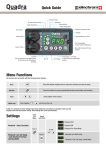
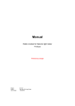
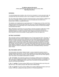
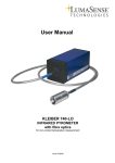
USER MANUAL GEBRAUCHSANLEITUNG MANUEL D’UTILISATION MANUAL DE FUNCIONAMIENTO MANUALE D’USO GEBRUIKSAANWIJZING РУКОВОДСТВО ПО ЭКСПЛУАТАЦИИ ユーザーマニュアル 用户手册 ELB 400 Elinchrom LTD – ELB 400 – 03.2015 – 73026 EN DE FR IT ES NL RU JP CN User Manual TABLE OF CONTENTS CONTROL PANEL 2 DISPLAY PANEL - DASHBOARD 3 DEDICATED BUTTON 3 MENU FEATURES 3 PHOTOCELL 4 MANUAL PRE-FLASH SETUP (FOR ADVANCED USERS) 4 EL-SKYPORT TRANSCEIVER FEATURES & SETUP 4 AUDIO 5 FLASH MODE 5 SEQUENCE SETUP 5 DELAY SETUP 6 STROBO SETUP 6 POWER SETTINGS 6 STATISTICS 7 TROUBLESHOOTING 7 SOFT RESET 7 FLASHTUBE REPLACEMENT 7 ERROR MANAGEMENT 8 TECHNICAL DATA 9 SUGGESTED VALUE TO SET ON THE ELB IN DELAYED MODE 10 QUADRA HEAD INFORMATION 11 BATTERY INFORMATION 12 EN Tolerances and specifications conforming to IEC and CE standards. Technical data subject to change without notice. 1 User Manual CONTROL PANEL 1 2 4 3 EN 5 6 13 7 12 11 10 9 8 CONTROL PANEL 2 1. Outlet B (33%) 8. Right function button / Power up 2. On / Off 9. Test button / Enter menu function 3. OLED display 10. Left function button / Power down 4. EL-Skyport antenna 11. Modelling lamp button 5. Synchronisation plug for 3.5 mm jack 12. Outlet A (100%) 6. Photocell 13. Access menu button / Return function 7. Micro USB socket / Firmware Update User Manual DISPLAY PANEL - DASHBOARD DISPLAY PANEL - DASHBOARD 1 2 3 4 5 6 7 > 85% DISPLAY PANEL - DASHBOARD 70% ~ 85% 55% ~ 70% 1 2 3 4 5 6 7 17 16 15 17 16 14 15 1 2 3 41 52 36 74 85 69 7 8 9 13 12 8 9 10 11 8 9 10 11 10 11 12 13 10 14 11 15 12 16 13 17 14 15 16 17 EL-Skyport synchronisation speed EL-Skyport frequency channel 14 13 12 EL-Skyport group number Photocell EL-Skyportstatus synchronisation speed Ready beepfrequency channel EL-Skyport Recycling time EL-Skyport group number Battery Photocelllevel status Power in J Ready beep Pilot lamp time timer Recycling Battery level Power in J Pilot lamp timer DEDICATED BUTTON 40% ~ > 55% 85% EN 20% 70% ~ 40% 85% < 70% 20% 55% ~ 40% ~ 55% 20% ~ 40% < 20% Flash function Flash function value Increase selected f-stop Flash Flash test function Decrease selected Flash function valuef-stop Power of selected outlet A inf-stop f-stop Increase Total Flashpower test in f-stop Power of outlet B inf-stop f-stop Decrease selected Power of outlet A in f-stop Total power in f-stop Power of outlet B in f-stop PILOT LAMP A short press on the pilot lamp button turns on the pilotlight of the Quadra Head for 15 seconds. Values can be changed from 1 – 60 seconds. A long press keeps the LED pilotlight on for as long as there is battery power. DISPLAY PANEL - MAIN MENU MENU FEATURES 1 DISPLAY PANEL MAIN DISPLAY PANEL - MAIN -MENU 1 6 5 4 3 6 5 4 3 MENU 1 2 3 2 41 25 63 2 4 5 6 Menu title Menu selected Scroll down Enter Menu title Scroll Menu up selected Back todown menu (Short press) Scroll Back Enter to dashboard (Long press) Scroll up Back to menu (Short press) Back to dashboard (Long press) 3 User Manual PHOTOCELL The photocell options allow you to switch the photocell on and off and to set up pre-flash for perfect synchronization with speedlites. DISPLAY OPTIONS PHOTOCELL off SUB-OPTIONS on EN Pre-flash From 1 to 10 pre-flashes set up pre-flash auto / manual / block time / timeframe When the photocell is on, the flash unit will trigger at any recognised flash impulse. The pre-flash option can be adjusted manually if the number of pre-flashes of the speedlite is known. Otherwise, simply choose “set up pre-flash” and release a speedlite exposure. The number of pre-flashes will be automatically detected and stored. You are now ready to work with your speedlites. MANUAL PRE-FLASH SETUP (FOR ADVANCED USERS) In some cases depending on the technology of the speedlite unit, the automatic pre-flash detection may not work. In this case you can try a manual setup. • manual : enter the number of pre-flashes from 1 to 20. • block time : set the delay between each pre-flash from 0.5 to 5 ms. • Timeframe : set the time window in which all pre-flashes, including the main flash, are released. Note : We cannot suggest any values or settings here; this depends on the speedlite unit and must be tested until the correct synchronisation between the flash unit and the speedlite is achieved. EL-SKYPORT TRANSCEIVER FEATURES & SETUP The EL-Skyport options allow you to select the synchronisation speed and to define group and channel settings. DISPLAY OPTIONS SKYPORT off r.0 SUB-OPTIONS normal r.1 speed r.2 group From “group 1” to “group 4” channel From “channel 1” to channel 20” If you work with the EL-Skyport system you can easily choose the synchronization speed. The “normal” synchronization mode is good when long distances are needed whereas the “speed” synchronization should be used when higher shutter speeds are needed with enabled digital cameras. Finally you can choose in which group and frequency you would like to work. Change group settings to have a better control between main light and second lights. Change frequency channel to avoid interference. 4 User Manual AUDIO The audio options give you the choice of different settings for when the capacitors are 100% charged and the unit is ready to flash. DISPLAY OPTIONS SUB-OPTIONS AUDIO ready volume From “off” to “max” error volume From “off” to “max” key volume From “off” to “max” ready tone From “tone 1” to “tone 2” EN The volume of the ready, error and key tones can be adjusted, enabling you to work silently if necessary. The ready tone can be chosen to improve acoustical recognition for when all flashes have fired and have recycled. FLASH MODE The flash mode menu enables you to configure your ELB unit to suit your style of shooting. DISPLAY OPTIONS SUB-OPTIONS FLASH MODE flash before ready disabled / enabled default unit address / total units/ seq. timeout sequence delayed set delay (in ms) strobo frequency / duration Setup the activated mode The flash before ready feature gives you the choice between flashing the unit before full recycle or to be able to flash only when the unit has fully recycled. Stay on default if you wish to do everyday flash photography. SEQUENCE SETUP Use sequence mode to catch a moving sequence with a number of indexed units, for example, of a jumping person in up to 20 different images. The following setup must be programmed in order to use the features. • unit address : Every unit requires its own address; every time a trigger is released the corresponding flash unit will respond. Up to 20 units can be addressed. • total units : Indicates the total number of addressed flash units. • sequence timeout : Time after which the sequence restarts back to first addressed unit. The timeout can be programmed from 0.1s to 5s. This setting is necessary to flash the addressed units in the right order. 5 User Manual DELAY SETUP Set a delay to your ELB unit to flash with a specific delay after triggering (e.g. second curtain). • EN Set delay (in ms) : Time in which the unit should fire a flash after the camera shutter has been opened. The delay time can be programmed from 1ms (0.001 s.) to 10000ms (10 s.). Please see the suggested values in the table page 10 if you want to have second curtain sync via skyport. Note : to fine-tune the miliseconds, the scale can be modified in 1, 10, 100 and 1000 steps. Press the User preset modelling lamp button to choose your step. This option is only active in the flash delay setup menu. STROBO SETUP Take an image with stroboscopic effects and open camera shutter. The overlapping moving sequence is visible in one image. • Frequency : Number of flashes per second. Programmable from 1 to 10Hz. • Duration window : Time during of the moving sequence you wish to capture. Programmable from 0.5 s. to 5 s. Note : The unit must be set in fast recycling time in the “power settings” menu. If the error sound is heard, this means the recycling time cannot follow the settings. Please reduce the Hz setting or the flash power to a lower value. POWER SETTINGS Power settings help you define standby and when to auto-off to save energy. You can also define recycling time depending on the battery level left. DISPLAY POWER SETTINGS OPTIONS SUB-OPTIONS auto standby From disabled to [60min] in steps of 1 min - default 10 minutes auto-off From disabled to [60min] in steps of 1 min - default 15 minutes pilot lamp timer From [1 sec] to [60 sec] in steps of 1 sec - default 15 sec. recycling time eco / fast step per push From [0.1 f-stop] to [1.0 f-stop] default 0.1 f-stop The standby option lets you decide after how long the unit goes into standby mode, enabling you to quickly turn the unit back on when needed. The auto-off option does just what its name suggests. When left unattended the unit will switch off automatically after the indicated time. The pilot lamp timer is dedicated to the LED Pilot lamp of the Quadra heads. Finally the step per push options enables you to modify in which steps you change the power on the dashboard. 6 User Manual STATISTICS Check lifetime of the unit and the flashtube. DISPLAY STATISTICS OPTIONS unit life flash count power-on cnt EN You can easily check the current usage of the unit and the flashtube. Very useful for servicing or second-hand retail. TROUBLESHOOTING SOFT RESET To reset all settings to default values, push the left and right buttons at the same time and hold for at least 1 second. The unit will reboot and will clear all working parameters. This will not reset the counter in the “Statistics” menu. FLASHTUBE REPLACEMENT Flashtubes have a long life with general use however multi-flashing in long sequences can cause overheating of the electrodes leading to premature ageing. If the flashtube is broken or cracked, triggers only sporadically, or you notice an important colour temperature shift, it could be that the flashtube of the Quadra head needs replacing. PREVIOUS GENERATION BATTERIES The ELB 400 can also work in conjunction with the older generations of batteries of the Ranger Quadra whether they are Lead-Gel or Lithium-Ion. 7 User Manual ERROR MANAGEMENT ERROR NUMBER EN 1 Capacitor over voltage 3 Discharge timeout error 4 Charge timeout error 15 Temperature sensor error 60 Communication bus error 90 Safety stop system (generic error) SOLUTION Switch the unit off, wait 2 minutes and switch the unit on again. If the error shows up again the unit requires a check up at an authorized Elinchrom service centre. 2 System over heat Wait until the unit has cooled down. The unit will switch back to the normal operation as soon as the temperature decreases to a normal working level. 11 Battery low The unit has detected a mains supply fault. Please check the mains/battery supply. It could be not working correctly. Battery unseal error Switch the unit off, wait 2 minutes and switch the unit on again. If the error shows up again the battery requires a check up at an authorized Elinchrom service centre. 61 8 DESCRIPTION User Manual TECHNICAL DATA Energy (Ws/J) Power distribution F-stop (1m, 100 ISO, reflector 48°) Pro Head Power range f-stop Power range Ws Power range Power increments in f-stop Flash duration t0.5 at max. power in s. : Pro/Action head 424 Asymmetrical 2 :1 At 100% : 64.5 – At 66% : 45.8 – At 33% : 32.8 6.9 100% : 21 - 424 – 66% : Output A : 14 - 280 – 33% : Output B : 7 - 140 1/1 – 1/32 1/10 to 5/10 - 1/1 Output A (100%) : 1/1200 / 1/2800 – Output B (33%) : 1/3000 / 1/5700 Output A+B (100%) : 1/1500 / 1/4000 Recycling, FAST in s. Output A : 0.3 - 1.6 – Output B : 0.17 - 0.7 Recycling, ECO in s. Output A : 0.5 - 3.5 – Output B : 0.3 - 1.2 Colour temperature in °K at max. power Auto Power Dumping Power stability Modelling lamp mode 5500 Adjusts power settings automatically ± 0.5% On, off, programmable timer and continuous Flashes out of one charged battery at min. power, ECO / FAST recycle 6000 / 5500 Flashes out of one charged battery at max. power, ECO / FAST recycle 350 / 350 Battery Quick charger : approx. recharge time EL-Skyport (Built-in) Lithium-Ion 14.4 V / 4.1 Ah 1h30m Integrated transceiver, 20 Frequency Channels and 4 Groups Sync voltage 5 V (compatible with all cameras) Sync socket 3.5 mm Jack Weight : ELB 400 unit including battery // Battery alone EN 2 kg // 0.73 Supplied with Battery, charger, sync cord and shoulder strap Code number 10279.1 9 User Manual SUGGESTED VALUE TO SET ON THE ELB IN DELAYED MODE* EN SYNC SPEED ON CAMERA EQUIVALENT IN MS 1/60 16.6 SUGGESTED VALUE 9 1/50 20 12 1/40 25 17 1/30 33.3 23 1/25 40 30 1/20 50 40 1/15 66.6 52 1/13 77 68 1/10 100 90 1/8 125 115 1/6 166.6 145 1/5 200 185 1/4 250 235 0.3" 300 290 0.4" 400 170 0.5" 500 470 0.6" 600 580 0.8" 800 750 1" 1000 950 1.3" 1300 1200 1.6" 1600 1500 2" 2000 1900 2.5" 2500 2400 3.2" 3200 2900 4" 4000 3800 5" 5000 4800 6" 6000 5800 8" 8000 7700 10" 10000 9700 * tested with canon EOS 5D. Suggested for fullframe camera. DECLARATION OF PERFORMANCE (DOP) For more information please visit www.elinchrom.ch/.... Find declaration for EC conformity and conformity USA & Canada on the Elinchrom website. www.elinchrom.ch 10 User Manual QUADRA HEAD INFORMATION FITTING REFLECTORS 1. Always switch off the unit before connecting accessories and reflectors. 2. Disconnect the flash cable from the ELB 400 pack. 3. Mount the Quadra head to a tripod and lock the security screw. 4. Place the reflector over the Quadra head, with the umbrella hole showing down. 5. Press the Quadra head locking knob firmly down and turn the reflector to the right until you hear the snap-in noise. 6. Check if the reflector is well fitted. 7. Reconnect the flash cable to the pack and switch the unit on. 8. Proceed in the same manner when exchanging reflectors. EN Push locking knob FLASHTUBE REPLACEMENT To exchange a user replaceable plug-in flashtube, please follow the instructions below: Switch the ELB 400 pack OFF. 1. Disconnect the cable first from the pack and secondly from the Quadra head. 2. Once the Quadra head has cooled down, place the head on a dry and clean surface. 3. 4. Attention: Use protective gloves to remove the flashtube: • Pull the flashtube firmly out of the terminals. • If the tube is broken, use security gloves. Avoid cutting yourself! • Never touch the metal electrodes and ensure that the unit is discharged and disconnected from the pack! Use an insulated tool to pull out the electrodes. Take the new flashtube. A protective gloves and/or insultated tissue MUST BE USED as any contact with your fingers on the glass may result in dark markings once the flashtube is in use. • For the Pro head use the horseshoe type flashtube / N° 24087 • For the Action head use the omega flashtube / N° 24086 5. Check that the tube is correctly aligned centrally and that the trigger contact is gripping the tube. 6. Re-connect and test the unit as usual. 11 User Manual EN Quadra Pro head - N° 20121 Quadra Action head - N° 20151 BATTERY INFORMATION • The battery can be charged at an ambient temperature from 0°C to +45°C, if the temperature is exceeded, the safety circuitry of the battery will shut down to avoid damage to the Li-Ion cells. • There is no memory-effect; our Lithium-Ion battery can be recharged from any charge level. • A completely charged battery will need to be recharged latest every 3 months. • Please refer to the battery guide to know how to take care of your battery in the best possible way. BATTERY FUSE The battery is secured with an ATO 20 A fuse. The topside of the battery includes transport pockets for two spare ATO 20 A fuses. When travelling by air and in general, remove the fuse to deactivate the battery and place the fuse into the free transport pocket! 1. Insert the 20 A fuse into the battery. 2. First connect the Elinchrom Li-Ion charger with the battery, and then connect the charger to the mains. 3. Charge the battery until the Elinchrom Li-Ion charger status light turns to green. 4. Press the battery button to check if the battery capacity is at 100% (4 green LEDs). 5. Remove first the mains connection, and then remove the charger from the battery. BATTERY STATUS The Li-Ion battery implements a full-integrated monitoring circuitry, which allows the user to know exactly the available capacity of the battery when pressing the push button, located on the front of the battery LED’s. 75% -100% 50% -75% 25% - 50% 10% - 25% < 10% 12 flashes