1
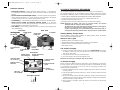
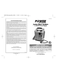
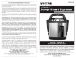
VEC026BD_Manual_050305
5/6/05
6:11 PM
Page 12
VEC026BD
TWO YEAR LIMITED WARRANTY PROGRAM
This limited warranty program is the only one that applies to this product, and it sets forth all the
responsibilities of manufacturer, regarding this product. There is no other warranty, other than those
described herein.
This Vector Manufacturing product is warranted, to the original purchaser only, to be free of defects in
materials and workmanship for two years from the date of purchase without additional charge. The
warranty does not extend to subsequent purchasers or users. Manufacturer will not be responsible for any
amount of damage in excess of the retail purchase price of the product under any circumstances. Incidental
and consequential damages are specifically excluded from coverage under this warranty.
This product is not intended for commercial use. This warranty does not apply to accessories or damage to
units from misuse or incorrect installation. Misuse includes wiring or connecting to improper polarity power
sources.
RETURN/REPAIR POLICY: Defective products, other than accessories, may be returned postage prepaid to
manufacturer. Any defective product, other than accessories, that is returned to manufacturer within 30 days
of the date of purchase will be replaced free of charge. If such a product is returned more than 30 days
but less than two years from the purchase date, manufacturer will repair the unit or, at its option, replace it
free of charge.
If the unit is repaired, new or reconditioned replacement parts may be used, at manufacturer’s option. A
unit may be replaced with a new or reconditioned unit of the same or comparable design. The repaired or
replaced unit will then be warranted under the terms of the remainder of the warranty period. The customer
is responsible for the shipping charges on all returned items after 30 days. During the warranty period,
manufacturer will be responsible for the return shipping charges.
LIMITATIONS: This warranty does not cover accessories, bulbs, fuses and batteries, defects resulting from
normal wear and tear (including chips, scratches, abrasions, discoloration or fading due to usage or
exposure to sunlight), accidents, damage during shipping to our service facility, alterations, unauthorized
use or repair, neglect, misuse, abuse, failure to follow instructions for care and maintenance, fire, flood and
Acts of God.
If your problem is not covered by this warranty, call Technical Support at (800) 618-5178 for general repair
information and charges if applicable. You may also contact us through our website at www.vectormfg.com.
STATE LAW RIGHTS: This warranty gives you specific legal rights. Some states do not allow limitations on
how long an implied warranty lasts or the exclusion or limitation of incidental or consequential damages,
so the exclusions or limitations stated herein may not apply. This warranty gives the purchaser specific legal
rights; other rights, which vary from state to state, may apply.
TO REQUEST WARRANTY SERVICE FOR THIS PRODUCT: Contact Technical Support by telephone, fax or
mail (see below). We suggest that you keep the original packaging in case you need to ship the unit. When
returning a product, include your name, address, phone number, dated sales receipt (or copy) and a
description of the reason for return and product serial number. After repairing or replacing the unit, we will
make every effort to return it to you within four weeks.
WARRANTY ACTIVATION: Please complete Warranty Activation Card and mail to Vector Manufacturing.
Enter “VEC026BD” as Model and “Electromate 400” as Product Type. All Vector products must be
registered within 30 days of purchase to activate this warranty. Mail the completed registration form, along
with a copy of the original sales receipt to:
ELECTROMATE 400
AC/DC Portable Power Supply
Jump-Starter/Inflator
Cordless • Rechargeable
USER’S MANUAL
& WARRANTY INFORMATION
ATTN.: CUSTOMER SERVICE
4140 SW 30th Ave., Ft. Lauderdale, FL 33312
• TOLL FREE: (800) 618-5178 • FAX: (954) 584-5556 •
IMPORTANT SAFETY INFORMATION, SAVE THESE INSTRUCTIONS
TO REDUCE THE RISK OF INJURY, USER MUST READ AND UNDERSTAND
THIS INSTRUCTIONAL MANUAL. THIS MANUAL CONTAINS IMPORTANT
INFORMATION REGARDING THE OPERATION AND WARRANTY OF THIS
PRODUCT. PLEASE RETAIN FOR FUTURE REFERENCE.
WARRANTY IS NON-TRANSFERABLE AND NON-REFUNDABLE.
BD050205
© 2005 VECTOR MANUFACTURING
MADE IN CHINA
12
4140 S.W. 30th Ave., Ft. Lauderdale, FL 33312 U.S.
Toll Free: (800) 618-5178
www.vectormfg.com
VEC026BD_Manual_050305
5/6/05
6:11 PM
Page ii
IMPORTANT SAFETY INSTRUCTIONS
WARNINGS
1. RISK OF EXPLOSIVE GAS MIXTURES — WORKING IN VICINITY OF A LEAD-ACID
BATTERY IS DANGEROUS. BATTERIES GENERATE EXPLOSIVE GASES DURING
NORMAL BATTERY OPERATION. FOR THIS REASON, IT IS OF UTMOST IMPORTANCE
THAT EACH TIME BEFORE USING YOUR CHARGER, YOU READ THIS MANUAL AND
FOLLOW THE INSTRUCTIONS EXACTLY.
2. To reduce risk of battery explosion, follow these instructions and those published by
the battery manufacturer and manufacturer of any equipment you intend to use in
vicinity of battery. Review cautionary markings on these products and on engine.
3. This equipment employs parts (switches, relays, etc.) that produce arcs or sparks.
Therefore, if used in a garage or enclosed area, the unit MUST be placed not less
than 18 inches above the floor.
Battery Safety
1. When working with lead acid batteries, always make sure immediate assistance is available in
case of accident or emergency.
2. Always use protective eyewear when using this product: contact with battery acid may cause
blindness and/or severe burns. Be aware of first aid procedures in case of accidental contact with
battery acid.
3. There is a risk of releasing explosive gases when lead acid batteries are charged or discharged.
Failure to follow instructions may cause property damage and/or personal injury.
4. When connecting the battery clamps to a discharged battery and an alarm sounds — the clamp
connections are incorrect and need to be reversed.
5. Jump-start procedures should only be performed in a safe, dry, well-ventilated area.
6. Always store battery clamps detached from unit when not in use. Never touch battery clamps
together. This can cause dangerous sparks, power arcing and/or explosion.
7. When using this unit close to the vehicle’s battery and engine, stand the unit on a flat, stable surface,
and be sure to keep all clamps, cords, clothing and body parts away from moving vehicle parts.
8. Do not wear vinyl clothing when jump-starting a vehicle, friction can cause dangerous staticelectrical sparks. Remove all jewelry or metal objects that could cause short circuits or react with
battery acid.
9. Never allow RED and BLACK clamps to touch each other or another common metal conductor —
this could cause damage to the unit and/or create a sparking/explosion hazard.
10. a. For negative-grounded systems, connect the POSITIVE (RED) clamp to the POSITIVE ungrounded
battery post and the NEGATIVE (BLACK) clamp to the vehicle chassis or engine block away from
the battery. Do not connect the clamp to the carburetor, fuel lines or sheet-metal body parts.
Connect to a heavy gauge metal part of the frame or engine block.
b. For positive-grounded systems, connect the NEGATIVE (BLACK) clamp to the NEGATIVE
ungrounded battery post and the POSITIVE (RED) clamp to the vehicle chassis or engine block
away from the battery. Do not connect the clamp to the carburetor, fuel lines or sheet-metal body
parts. Connect to a heavy gauge metal part of the frame or engine block.
11. Always disconnect the NEGATIVE (BLACK) jumper cable first, followed by the POSITIVE (RED)
jumper cable, except for positive grounded systems.
12. Do not expose battery to fire or intense heat since it may explode. Before disposing of the battery,
protect exposed terminals with heavy-duty electrical tape to prevent shorting (shorting can result in
injury or fire).
13. Do not smoke or use flammable items (matches, cigarette lighters, etc.) while working on a vehicle’s
battery system.
14. Whether stored or in use, keep this unit out of reach of children.
15. Do not operate charger in rain or snow, nor use when wet.
16. DO NOT ATTEMPT TO JUMP-START A FROZEN BATTERY.
17. When using an extension cord, make sure it has the same configuration as the plug of the unit and
the cord is properly wired and in good electrical condition. This cord needs to be suitable for 120
volt AC and have a minimum 2 amp rating.
18. Place this unit as far away from the battery as DC cables permit.
19. Never allow battery acid to come in contact with this unit.
20. Do not operate this unit in a closed area or restrict ventilation in any way.
ii
Personal Safety
FIRST AID
SKIN: If battery acid comes in contact with skin, rinse immediately with water, then wash thoroughly with
soap and water. If redness, pain, or irritation occurs, seek immediate medical attention.
EYES: If battery acid comes in contact with eyes, flush eyes immediately, for a minimum of 15 minutes
and seek immediate medical attention.
IMPORTANT
This unit is delivered in a partially charged state. Fully charge unit with the supplied 120 volt AC charger
for a full 40 hours before using for the first time. You cannot overcharge the unit using the AC charger
method.
1. Use a common household extension cord for charging (not supplied).
2. Do not recharge for more than 5-6 hours maximum using the 12 volt DC method. Recharge unit
after each use.
3. All ON/OFF switches should be in the OFF position when the unit is charging or not in use. Make
sure all switches are in the OFF position before connection to a power source or load.
4. Never insert anything other than the supplied power/recharging cords or recommended appliance
power/recharging cords into the 12 volt DC charging/power outlet on this unit. Do not use any
accessory that is not recommended or provided by the manufacturer.
5. Do not use this unit to operate appliances that need more than 5 amps to operate from the 12 volt
DC accessory outlet.
6. This system is designed to be used only on vehicles with a 12 volt DC battery system. Do not
connect to a 6 volt or 24 volt battery system.
7. This system is not designed to be used as a replacement for a vehicular battery. Do not attempt to
operate a vehicle that does not have a battery installed.
8. Vehicles that have on-board computerized systems may be damaged if vehicle battery is jumpstarted. Before jump-starting, read the vehicle’s owners manual to confirm that external-starting
assistance is suitable.
9. Excessive engine cranking can damage a vehicle’s starter motor. If the engine fails to start after the
recommended number of attempts, discontinue jump-start procedures and look for other problems
that may need to be corrected.
10. Although this unit contains a non-spillable battery, it is recommended that unit be kept upright
during storage, use and recharging. To avoid possible damage that may shorten the unit’s working
life, protect it from direct sunlight, direct heat and/or moisture.
11. Check unit periodically for wear and tear. Take to a qualified technician for replacement of worn
or defective parts immediately.
12. NEVER submerge this unit in water.
13. DO NOT overinflate tires.
SAVE THESE INSTRUCTIONS
This device complies with part 15 of the FCC rules. Operation is subject to the following two
conditions: (1) this device may not cause harmful interference, and (2) this device must accept any
interference received, including interference that may cause undesired operation.
This equipment has been tested and found to comply with the limits for a Class B digital device,
pursuant to part 15 of the FCC Rules. These limits are designed to provide reasonable protection
against harmful interference in a residential installation. This equipment generates, uses and can
radiate radio frequency energy and, if not installed and used in accordance with the instructions,
may cause harmful interference to radio communications. However, there is no guarantee that
interference will not occur in a particular installation. If equipment does cause harmful interference
to radio or television reception, which can be determined by turning the equipment off and on, the
user is encouraged to try to correct the interference by one or more of the following measures:
• Reorient or relocate the receiving antenna.
• Increase the separation between equipment and receiver.
• Connect the equipment into an outlet on a circuit different from that to which the receiver is
connected.
• Consult the dealer or an experienced radio/TV technician for help.
iii
VEC026BD_Manual_050305
5/6/05
6:11 PM
Page iv
TABLE OF CONTENTS
Introduction . . . . . . . . . . . . . . . . . . . . . . . .
Features . . . . . . . . . . . . . . . . . . . . . . . . . .
AC and DC Charging/Recharging . . . . . . . .
Viewing Battery Charge Status . . . . . . . . .
120 Volt AC Charging . . . . . . . . . . . . . .
12 Volt DC Charging . . . . . . . . . . . . . . .
Using the Electromate as a Jump-Starter . . . .
Using the Alternator Check Feature . . . . . . .
Using the 12 Volt Portable Power Supply . . .
Using the 120 Volt AC Power Supply . . . . . .
Using the Emergency Area Light . . . . . . . . . .
Using the Tire Inflator . . . . . . . . . . . . . . . . .
Inflating Products With a Valve Stem . . . .
Inflating Products Without a Valve Stem . .
Care and Maintenance . . . . . . . . . . . . . . . .
Replacement Parts . . . . . . . . . . . . . . . . .
Battery Replacement/Disposal . . . . . . . . .
Fuse Replacement (DC Accessory Adapter)
Specifications . . . . . . . . . . . . . . . . . . . . . . .
.
.
.
.
.
.
.
.
.
.
.
.
.
.
.
.
.
.
.
.
.
.
.
.
.
.
.
.
.
.
.
.
.
.
.
.
.
.
.
.
.
.
.
.
.
.
.
.
.
.
.
.
.
.
.
.
.
.
.
.
.
.
.
.
.
.
.
.
.
.
.
.
.
.
.
.
.
.
.
.
.
.
.
.
.
.
.
.
.
.
.
.
.
.
.
.
.
.
.
.
.
.
.
.
.
.
.
.
.
.
.
.
.
.
.
.
.
.
.
.
.
.
.
.
.
.
.
.
.
.
.
.
.
.
.
.
.
.
.
.
.
.
.
.
.
.
.
.
.
.
.
.
.
.
.
.
.
.
.
.
.
.
.
.
.
.
.
.
.
.
.
.
.
.
.
.
.
.
.
.
.
.
.
.
.
.
.
.
.
.
.
.
.
.
.
.
.
.
.
.
.
.
.
.
.
.
.
.
.
.
.
.
.
.
.
.
.
.
.
.
.
.
.
.
.
.
.
.
.
.
.
.
.
.
.
.
.
.
.
.
.
.
.
.
.
.
.
.
.
.
.
.
.
.
.
.
.
.
.
.
.
.
.
.
.
.
.
.
.
.
.
.
.
.
.
.
.
.
.
.
.
.
.
.
.
.
.
.
.
.
.
.
.
.
.
.
.
.
.
.
.
.
.
.
.
.
.
.
.
.
.
.
.
.
.
.
.
.
.
.
.
.
.
.
.
.
.
.
.
.
.
.
.
.
.
.
.
.
.
.
.
.
.
.
.
.
.
.
.
.
.
.
.
.
.
.
.
.
.
.
.
.
.
.
.
.
.
.
.
.
.
.
.
.
.
.
.
.
.
.
.
.
.
.
.
.
.
.
.
.
.
.
.
.
.
.
.
.
.
.
.
.
.
.
.
.
.
.
.
.
.
.
.
.
.
.
.
.
.
.
.
.
.
.
.
.
.
.
.
.
.
.
.
.
.
.
.
.
.
.
.
.
.
.
.
.
.
.
.
.
.
.
.
.
.
.
.
.
.
.
.
.
.
.
.
.
.
.
.
.
.
.
.
.
.
.
.
.
.
.
.
.
.
.
.
.
.
.
.
.
.
.
.
.
.
.
.
.
.
.
.
.
.
.
.
.
.
.
.
.
.
.
.
1
1
3
3
3
3
4
5
5
6
7
7
7
8
9
9
9
9
9
INTRODUCTION
Thank you for purchasing the Black & Decker VEC026BD Electromate 400.
Please read this guide carefully before use to ensure optimum performance and
avoid damage to the unit.
FEATURES
• Powers 110/120 volt AC appliances
• Powers 12 volt DC appliances
• Jump-starts vehicle engines
• Built-in inflator
• Built-in 400 watt inverter
• Includes non-spillable, maintenance-free, heavy-duty, sealed battery
• Safe to use, transport and store
• Alternator check
• Reverse polarity connection warning
• Detachable jumper cables
• Requires no maintenance (other than recharging) for optimum operation
• Rechargeable with built-in AC charger
• Unique compact design provides completely portable 12 volt DC power
• Molded high-impact case is tough and durable
• Built-in area light for night time roadside repairs and use in remote locations without
utility power
• Battery charge level indicators
iv
1
VEC026BD_Manual_050305
5/6/05
6:11 PM
Page 2
Protective Features
AC AND DC CHARGING/RECHARGING
• Automatic Overload — Built-in protection against overload — in the event the
AC outlet draws more than 400 watts, power to the unit’s outlet will automatically
shut off.
• Ground Fault Circuit Interrupter (GFCI) — The GFCI protects the unit and the
user by sensing imbalances in a circuit caused by current leakage to the ground
and shuts down the unit’s AC outlet to prevent electrical shock.
• Overheating — Unit automatically shuts down if it exceeds a safe temperature.
• Safety Power Switch and Reverse Polarity Alarm — In event the
cables/clamps are reversed during jump-starting, an indicator lights and an alarm
sounds BEFORE the Power Switch is turned ON.
• Low Battery — If the battery power level is too low, the AC Power Supply shuts
down automatically.
Use a common household AC extension cord for charging (cord not supplied).
For maximum battery life, we recommend the unit be kept fully charged at all times.
If the battery is allowed to remain in a discharged state, battery life will be shortened.
• MAKE SURE ALL SWITCHES ARE TURNED OFF DURING RECHARGING.
• Charge the unit for a full 24 hours using AC method before first use.
• Recharge the unit fully after each use.
• Recharge the unit every two months when it has not been used regularly.
Front View
UNIT FRONT PANEL
Back View
RUBBER HANDLE
JUMPER CABLE
CONNECTOR
AIR VENTS
DC POWER SUPPLY
PANEL
AC POWER SUPPLY
PANEL
12 VOLT DC ADAPTER
STORAGE
COMPARTMENT
AC CHARGER
ALTERNATOR CHECK
INDICATOR
REVERSE POLARITY
INDICATOR
INFLATOR PRESSURE
GAUGE
INFLATOR
ON/OFF SWITCH
AREA LIGHT
ON/OFF SWITCH
AREA LIGHT
Air Inflator Nozzles
2
Viewing Battery Charge Status
120 Volt AC Charging
INFLATOR
BATTERY CHARGE LEVEL
PUSHBUTTON
JUMP-START SAFETY
ON/OFF SWITCH
discharges between recharges reduces battery life.
The Electromate also comes with a DC/DC charging adapter for recharging the
unit from a 12 volt DC accessory outlet in a vehicle.
If unit is fully discharged, it is recommended that the vehicle being used for
recharging be left running while the unit is charged via the 12 volt DC method.
Press the Battery Charge Level pushbutton to display battery status. The Battery
Charge Level Indicator LEDS will light.
LEDS (from left to right):
• Red LED indicates a low battery charge
• Two Red LEDs indicate a medium level or partially charged battery
• Two Red and one Green LED indicates a full or high
level battery charge.
Front Panel
BATTERY CHARGE
LEVEL INDICATORS
Notes: Recharging the battery after each use prolongs battery life; frequent
1. Lift the AC adapter cover located on the back of the Electromate and connect
an extension cord to the unit. Plug the other end of the cord into a standard
120 volt AC wall outlet.
2. Charge until two Red and one Green LEDs light.
3. Once fully charged, disconnect the extension cord.
Note: The unit cannot be overcharged using the AC method.
12 Volt DC Charging
The DC recharging method will NOT recharge the unit as effectively as recharging
from 120 volt AC. The 12 volt DC recharging procedure is recommended only when
it is necessary, since frequent use of the 12 volt DC recharging procedure may
shorten the battery system’s life.
1. Insert the gold-tipped DC/DC charging adapter plug into the vehicle’s 12 volt DC
accessory outlet.
2. Insert the silver-tipped end plug into the 12 volt DC accessory outlet on the front
panel of the unit.
3. To check the charge status of the battery during DC charging, disconnect the DC
adapter from the accessory outlet and push the Battery Charge Level pushbutton.
Observe the battery charge indicator.
4. When charging is complete, remove the power cord and return it to the storage
compartment.
3
VEC026BD_Manual_050305
5/6/05
6:11 PM
Page 4
WARNING
Do not recharge for more than 5 to 6 hours maximum using the 12
volt DC method.
USING THE ELECTROMATE AS A JUMP-STARTER
WARNING
Before using this system to jump-start any vehicle read and
understand all instructions, safety tips, warnings, cautions and first
aid information provided in this manual and on the product labeling.
Additional important information may also be provided by the
vehicle’s battery system manufacturer.
CAUTION
To avoid possible damage that may shorten the unit’s working life,
protect this unit from direct sunlight, direct heat and moisture.
This system is to be used ONLY on vehicles, garden tractors and
gasoline-powered generators with 12 volt DC battery systems.
This system is NOT designed to be installed as a replacement for a
vehicle battery.
WARNING
Connect or disconnect battery leads ONLY when AC or DC charging
supply cord is disconnected.
Jump-Starting Instructions
This jump-starter is equipped with a manual safety switch that only allows jump-start
energy to flow when proper connections are made to battery and frame.
Connect — RED clamp first, then BLACK clamp. Disconnect — BLACK clamp first,
then RED clamp.
1. Turn OFF vehicle ignition and all accessories (radio, A/C, lights, cell phone, etc.).
Place vehicle in “park” and set the emergency brake.
2. Make sure jump-start system’s ON/OFF power switch is turned to OFF.
3. Connect jumper cables to unit.
4. To jump-start a NEGATIVE GROUNDED SYSTEM (NEGATIVE battery terminal
is connected to the chassis — the most common configuration), follow steps 4a
and 4b, then proceed to step 6.
4a. Connect the POSITIVE (+) RED clamp to vehicle battery’s POSITIVE
ungrounded post.
4b. Connect the NEGATIVE (–) BLACK clamp to the vehicle chassis or engine
block away from the battery. Do not connect the clip to carburetor, fuel lines
or sheet-metal body parts. Connect to a heavy gauge metal part of the frame
or engine block.
5. To jump-start a POSITIVE GROUNDED SYSTEM — In the rare event that the
vehicle to be started has a POSITIVE Grounded System, POSITIVE battery
terminal is connected to chassis, replace steps 4a and 4b above with steps 5a
and 5b, then proceed to step 6.
4
5a. Connect NEGATIVE (–) BLACK clamp to vehicle battery’s NEGATIVE
ungrounded post.
5b. Connect POSITIVE (+) RED clamp to the vehicle chassis or engine block
away from the battery. Do not connect the clip to carburetor, fuel lines or
sheet-metal body parts. Connect to a heavy gauge metal part of the frame
or engine block.
DO NOT TURN SAFETY SWITCH ON IF REVERSE POLARITY ALARM
SOUNDS OR THE REVERSE POLARITY INDICATOR LIGHTS. REVERSE
THE CLAMP CONNECTIONS.
6. After making proper connections, turn safety power switch to ON.
7. Start vehicle (do not turn key for longer than 5-6 seconds).
8. After vehicle starts, turn the safety power switch to off, remove clamps (disconnect
the frame or engine clamp first, followed by the battery cable). Disconnect the
cables from unit.
Notes: Always disconnect the engine or frame jumper clamp first; followed by
the battery jumper clamp.
If engine fails to start, leave the ignition turned off and disconnect the
NEGATIVE (–) clamp first, then the POSITIVE (+) clamp. Try again later —
the engine may be flooded.
Recharge the Electromate after each use.
USING THE ALTERNATOR CHECK FEATURE
1. Turn the safety switch to the OFF position.
2. Connect jumper cables to unit.
3. Connect to vehicle.
4. Start engine.
5. Turn vehicle accessories off.
6. A solid LED indicates a good alternator. A flashing LED indicates a bad
alternator.
USING THE 12 VOLT DC PORTABLE POWER SUPPLY
1. Flip open one of the 12 volt DC outlet covers on the DC Power Supply Panel.
2. Insert the 12 volt DC plug from the appliance into the outlet.
3. Turn on the appliance and operate normally.
DC Power Supply Panel
12 VOLT DC OUTLETS
AIR VENTS
CAUTION
DO NOT USE UNIT TO POWER APPLIANCES THAT DRAW MORE THAN
5 AMPS DC.
5
VEC026BD_Manual_050305
5/6/05
6:11 PM
Page 6
USING THE 120 VOLT AC POWER SUPPLY
USING THE EMERGENCY AREA LIGHT
The 120 Volt AC Power Supply is designed for maintaining today's modern lifestyle
while traveling in vans, RVs, automobiles, trucks, or vehicles that have a 12 volt DC
battery power supply and a means to recharge those batteries. The Electromate
400 comes with:
1. AC ON/OFF Switch — Slide switch to turn the AC Power Supply ON and OFF.
2. 120 Volt AC Power Outlets
3. AC Power Supply “ON” Status Indicator — green LED lights when AC outlet is
turned on; green LED flashes on and off when faulted.
4. AC Power Ground Fault Circuit Interrupt (GFCI) — a 3-prong outlet for 120 volt
AC appliances which shuts down inverter if leakage or ground fault current is
detected.
5. Internal protective circuits including:
• Overload and over-temperature shutdown (activated if AC output exceeds 400
watts)
• AC short-circuit shutdown
• Low voltage shutdown
• A new cooling technology that more efficiently cools the power transistors and,
combined with soft start, dramatically increases reliability and product life
The Area Light is controlled by an ON/OFF pushbutton. Make sure the light is turned
OFF when the unit is being recharged or stored.
AC Power Supply Controls and Indicators
The illustration below details the AC Power Supply front panel. Air vents keep the unit
from overheating. An ON/OFF switch turns the AC power circuitry on and off. The
ON/OFF switch can also be used to reset the AC power after shutdown due to
overvoltage, overload or over-temperature condition. The “ON” status indicator lights
when the AC power supply is on. The AC outlets (covered when not in use) supply
power to AC appliances.
AC Power Supply Front Panel
AC POWER SUPPLY
“ON” STATUS
INDICATOR
AC POWER SUPPLY
ON/OFF SWITCH
USING THE TIRE INFLATOR
Read Instructions Carefully to Avoid Possible Injury or Property
Damage.
The built-in 12 volt DC inflator is the ultimate inflator for all vehicle tires, trailer tires
and recreational inflatables. Three different sized nozzles are supplied. Each nozzle
clips on the end of the standard tire valve connector attached to the free end of the
inflator hose. The inflator hose with tire fitting is stored in a retaining channel between
the jumper cable channels on the rear of the unit. The ON/OFF switch is located on
the front of the unit. The inflator can operate long enough to fill up to 3 average sized
tires before the battery must be recharged. The inflator may be used by removing the
air hose from the storage hatch and, if required, fitting the appropriate nozzle to the
air hose. Return the hose to the storage compartment after use.
Note: Thermo-protection device shuts down the unit when the unit overheats and
restarts once the unit has reached a safe operating temperature.
WARNING
The inflator is capable of inflating up to 120 pounds per square inch
(psi) pressure. To avoid over inflating, carefully follow instructions on
articles to be inflated. Never exceed recommended pressures. Always
check pressure with the pressure gauge. Never leave the inflator
unattended while in use. Bursting articles can cause serious injury.
CAUTION
Do not operate inflator continuously for extended periods of time
(approx. 15 minutes, depending on the ambient temperature), as it
may overheat. In such event, inflator will shut down and restart after a
cooling period of approximately 15 minutes.
Inflating Products With a Valve Stem
120 VOLT AC
OUTLETS
AIR VENTS
1. Place standard connector (chuck) on valve stem.
2. Push connector toward valve stem and close thumb latch.
Note: Make sure connector is pushed onto valve stem as far as possible
before closing thumb latch.
AC Power Supply Operation
1. Turn power switch to ON (the power indicator lights).
2. Plug in appliance and turn the appliance on.
3. Slide inflator switch to ON.
4. Check pressure with the pressure gauge.
5. When desired pressure is reached, slide the inflator switch to OFF; open thumb
latch and remove connector from valve stem.
6. Store inflator hose and tire fitting in storage compartment.
Note: The AC power supply shuts down automatically when the battery voltage level
is too low. If the green LED flashes, a faulty condition such as an overload,
overheating or short circuiting has occurred. Turn the AC Power Supply OFF and
unplug the appliance. Wait a few minutes, then turn power back ON.
6
7
VEC026BD_Manual_050305
5/6/05
6:11 PM
Page 8
CARE AND MAINTENANCE
Inflating Products Without a Valve Stem
Inflation of other items requires use of one of the adapters (nozzles).
1. Insert appropriate adapter (e.g. needle) into connector (chuck) and close thumb
latch.
2. Insert adapter (e.g. needle) into item to inflate.
3. Slide inflator switch to ON.
4. Refer to the following table for approximate filling pressure and time. Small items
such as volleyballs, footballs, etc. inflate very rapidly.
5. Slide inflator switch to OFF.
6. Remove adapter from item and store properly.
Typical Inflation Times
Inflation pressure (psi)
Vehicle and trailer tires
155/80R 13"
185/70R 14"
235/75R 16"
235/70R 17"
Bicycle tires
27" X 1" (racing)
Football
Basketball
Volleyball
Approx. Filling time
26
30
30
42
2.5
4.5
6.5
16
min.
min.
min.
min.
90
13
10
5
40 sec.
24 sec.
20 sec.
6 sec.
WARNING
Always follow tire manufacturer’s recommendations for pressure on
item to be inflated.
CAUTION
If the cord, wires, or cables become damaged, return the entire unit
to Vector Manufacturing immediately for service/repair.
Replacement Parts
For replacement parts (bulbs, batteries, fuses, etc.), contact Customer Service, tollfree, at (800) 618-5178.
Battery Replacement/Disposal
It is recommended that the unit be returned to Customer Service
for battery replacement.
This unit contains a maintenance-free, non-spillable, sealed leadacid battery. This battery is fully recyclable and should be
accepted at any location that accepts common automotive
starter batteries. Examples of places that accept these batteries
are: county or municipal recycling drop-off centers, scrap metal
dealers and retailers who sell automotive replacement lead acid
starter batteries.
WARNINGS
Do not dispose of the battery in fire, as this may result in an explosion.
Before disposing of the battery, protect exposed terminals with
heavy-duty electrical tape to prevent shorting (shorting can result in
injury or fire).
Do not expose battery to fire or intense heat, as it may explode.
Fuse Replacement (DC Accessory Adapter)
1. Remove plug from accessory outlet. Remove the gold cap by turning counterclockwise and lifting off.
2. Remove center pin and spring. Remove fuse.
3. Replace fuse with same type and size fuse (8 amp).
4. Replace center pin and spring inside plug.
5. Replace gold cap by turning clockwise.
SPECIFICATIONS
12 Volt DC Specifications
8
Battery:
12 volt DC rechargeable, maintenance-free
Internal Battery Type:
Sealed, AGM lead-acid
Internal Battery
Capacity:
12 volt 19Ah/20 hour rate
Area Light :
Light Emitting Diode (LED)
Jumper Cables:
Heavy duty welding cable
with 450 amp clamps
9
VEC026BD_Manual_050305
Accessory Outlet
Protection:
5/6/05
6:11 PM
Page 10
Self-resetting overload protection
DC Charging Adapter: 12 volt DC
AC Power Specifications
Output Power:
Continuous — 400 watts
Output Voltage:
120 VAC RMS
Output Frequency:
60 Hz ±4 Hz
Output Waveform:
Modified sine wave
Overheat Protection:
Yes
Overload Protection:
Yes
Output Short Circuit
Protection:
Yes
Tire Inflator Specifications
Maximum Pressure:
120 PSI
Battery Charger Specifications
Input:
120 volt AC, 60 Hz
Rapid Charging
Current:
12 volt DC 1000mA
10
11