1
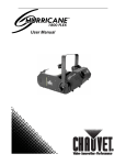
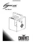
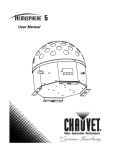
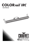
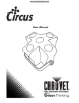
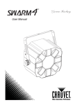
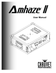
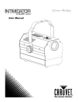
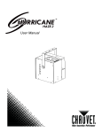
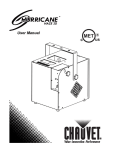
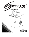
User Manual TABLE OF CONTENTS 1. Before You Begin ............................................................................. 3 What Is Included ........................................................................................... 3 Unpacking Instructions .................................................................................. 3 Claims .................................................................................................................... 3 Text Conventions .......................................................................................... 3 Icons .............................................................................................................. 3 Safety Notes .................................................................................................. 4 2. Introduction ...................................................................................... 5 Product Overview .......................................................................................... 5 3. Setup ................................................................................................. 6 AC Power ...................................................................................................... 6 Resetting the Breaker ................................................................................... 6 Mounting ....................................................................................................... 7 Orientation ............................................................................................................. 7 Rigging ................................................................................................................... 7 4. Operation .......................................................................................... 8 Control Panel Operation................................................................................ 8 Menu Map ..................................................................................................... 8 DMX Channel Assignments and Values ....................................................... 8 Configuration (DMX Mode) ........................................................................... 9 Starting Address..................................................................................................... 9 Configuration (Stand-alone Modes) ............................................................ 10 Timer Mode .......................................................................................................... 10 Volume Mode ....................................................................................................... 10 5. Technical Information.................................................................... 11 General Maintenance .................................................................................. 11 Storage ........................................................................................................ 11 General Troubleshooting ............................................................................ 12 Returns Procedure ...................................................................................... 13 Contact Information ..................................................................................... 13 DMX Primer ................................................................................................. 14 Starting Address................................................................................................... 14 Fixture Linking (Daisy Chain) ............................................................................... 14 DMX Cabling ........................................................................................................ 15 6. Technical Specifications ............................................................... 16 Page 2 of 16 Arena™ Hazer 3 User Manual (Rev. 02) 1. BEFORE YOU BEGIN What Is Included 1 x Arena™ Hazer 3 1 x Power Cord 1 x Warranty Card 1 x User Manual Unpacking Instructions Immediately upon receiving this product, carefully unpack it and check the container in which you received it. Make sure that you have received all the parts indicated above and that they are all in good condition. Claims If the container or the product inside the container (including any accessories) appears damaged from shipping or signs of mishandling, notify the carrier immediately, not CHAUVET®, upon receipt of the damaged merchandise. Failure to do so in a timely manner may invalidate your claim with the carrier. In addition, retain the container and all the packing material for inspection. For other issues such as missing components or parts, damage not related to shipping, or concealed damage, file a claim with CHAUVET® within seven (7) days of receiving the merchandise. Text Conventions Convention <Menu> 1~512 50/60 Settings Menu > Settings Meaning A key to be pressed on the fixture’s control panel A range of values A set of values of which only one can be chosen A menu option not to be modified (for example, showing the operating mode/current status) A sequence of menu options to be followed ON A value to be entered or selected Icon Meaning Icons This paragraph contains critical installation, configuration, or operation information. Failure to comply with this information may render the fixture partially or completely inoperative, cause damage to the fixture, or cause harm to the user. This paragraph contains important installation or configuration information. Failure to comply with this information may prevent the fixture from functioning correctly. This paragraph reminds you of useful, although not critical, information. Document Information The information and specifications contained in this document are subject to change without notice. CHAUVET® assumes no responsibility or liability for any errors or omissions that may appear in this manual. © Copyright 2011 CHAUVET®. All rights reserved Printed in P.R.C. Electronically published by CHAUVET® in the United States of America Author Editor Manager PD Manager A. Chiappone B. Pillow A. Reiss F. Sellers Arena™ Hazer 3 User Manual (Rev. 02) Page 3 of 16 Product at a Glance Use on Dimmer Outdoor Use Sound Activated DMX Master/Slave Auto Programs Auto-ranging Power Supply Replaceable Fuse User Serviceable Duty Cycle Safety Notes Please read the following notes carefully before starting to work with this product. They include important safety information about its installation, usage, and maintenance. Keep this User Manual for future consultation. If you sell this product to another user, be sure that they also receive this document. Always make sure that the voltage of the outlet to which you are connecting this product is within the range stated on the decal or rear panel of the fixture. This product is for indoor use only! To prevent risk of fire or shock, do not expose this fixture to rain or moisture. Make sure there are no flammable materials close to the unit while operating. Always install this product in a location with adequate ventilation, at least 20 in (50 cm) from adjacent surfaces. Be sure that no ventilation slots on the unit’s housing are blocked. Always disconnect this product from the power source before cleaning it or replacing fuse. Make sure to replace the fuse with another of the same type and rating. The maximum ambient temperature (Ta) is 104° F (40° C). Do not operate this product at higher temperatures. In the event of a serious operating problem, stop using the unit immediately. Never try to repair this product. Repairs carried out by unskilled people can lead to damage or malfunction. Please contact the nearest authorized technical assistance center. Never connect this product to a dimmer pack. Make sure the power cord is not crimped or damaged. Never disconnect the power cord by pulling or tugging on the cord. Never carry a fixture from the power cord or any moving part. Always use the hanging/mounting bracket or the handles. Always avoid direct eye exposure to the light source when this fixture is on. Do not touch the output nozzle on this product. It is very hot during operation and it may remain hot for several hours after turning the unit off. Do not mount this product on a flammable surface (e.g., wood, linoleum, carton, plastic, or carpet). Make sure there are no flammable materials close to the unit while operating. Depending on the amount of fog/haze generated, all fog machines may set off smoke detectors. FCQ (Fog Cleaner Quart) was specifically developed by Chauvet to clean your Arena™ Hazer 3. Make sure you use FCQ regularly to increase the life of your product. Page 4 of 16 Arena™ Hazer 3 User Manual (Rev. 02) 2. INTRODUCTION Product Overview Carrying handle Fluid reservoir cover Haze output nozzle Air filter Rubber feet (4) DMX (3-pin & 5-pin) LCD screen (Control Panel) Power Switch (ON/OFF) Power Input (NEUTRIK® powerCON® A) Main Breaker Arena™ Hazer 3 User Manual (Rev. 02) Page 5 of 16 3. SETUP AC Power This product uses a transformer-based power supply with a fixed input voltage of either 120 V, 60 Hz or 230 V, 50 Hz. To determine the power requirements for a particular fixture, see the label affixed to the back plate of the fixture or refer to the fixture’s specifications chart. A fixture’s listed current rating indicates its average current draw under normal conditions. Always connect this product to a protected circuit (circuit breaker or fuse), making sure that it has an appropriate electrical ground to avoid the risk of electrocution or fire. Never connect this product to a rheostat (variable resistor) or dimmer circuit, even if the rheostat or dimmer channel serves only as a 0 to 100% switch. Resetting the Breaker This product is equipped with a resettable circuit breaker on the power input circuit. In the event that the breaker trips, the power will be cut to the entire product. Please see the instructions below for resetting this breaker. 1. Remove the power cord from mains power. 2. Allow unit to cool for 15 minutes. 3. After 15 minutes, you may attempt to reset the breaker by pressing the button with your index finger. 4. Plug the fixture power cord into the power outlet and continue recommended use. In the event that the breaker will not reset (the breaker button will not remain inserted), contact CHAUVET® immediately, as this indicates a possible internal malfunction. Page 6 of 16 Arena™ Hazer 3 User Manual (Rev. 02) Mounting Orientation The Arena™ Hazer 3 is a haze machine and it uses fluid. Keep this in mind when selecting the orientation, as the fluid will leak out of the fluid reservoir if the unit is not horizontal. Rigging When hanging this product overhead, always use all three of the fly points. The cables and structure to which you are hanging the product from must be capable of supporting at least 10 times the weight of the Arena™ Hazer 3. Please see the “Technical Specifications” section of this manual for weight information. Always consider ease of access to the unit for maintenance and programming purposes before deciding on a location for this product. Overhead rigging is potentially dangerous and should only be attempted by certified/experienced riggers. The installer/user is responsible for ensuring that the Arena™ Hazer 3 is rigged safely, following current national, state, and local regulations. CHAUVET® recommends that the unit be inspected every 90 days. If any damage is detected, remedial action should be taken immediately! Fly point Fly point Mounting Diagram (Side & Front) Fly point Fly point Fly point Arena™ Hazer 3 User Manual (Rev. 02) Page 7 of 16 4. OPERATION Control Panel Operation To access the control panel functions, use the four buttons located underneath the display. Button Function <MODE/ESC> <DOWN> <UP> <ENTER> Press to find an operation mode or to back out of the current menu option Press to scroll down the list of options or to find a lower value Press to scroll up the list of options or to find a higher value Press to activate a menu option or a selected value Menu Map Mode Programming Steps Interval Set 1~200s Modify the interval time for the timer mode Duration Set 1~200s Modify the duration time for the timer mode Timer Out 1~100% Modify the haze volume for the timer mode Volume Out 1~100% Fan Speed Description Modify the volume output for volume mode OFF, 1~100% DMX512 Add. 1~512 Fluid Sensor ON/OFF EMPTY FLUID “blinking" Modify the fan speed for both the time & volume modes Set the DMX starting address Turn on/off the internal fluid sensor When this is blinking on the LCD screen, fluid needs to be added to the fluid reservoir in order to continue either volume or timer operation DMX Channel Assignments and Values Channel 1 2 Page 8 of 16 Function Blower Haze Value Setting 000 255 0~100% 000 255 0~100% Arena™ Hazer 3 User Manual (Rev. 02) Configuration (DMX Mode) Setting this product to operate in DMX mode will allow you to control it with a DMX controller. 1. Connect this product to a suitable power outlet. 2. Turn this product on. 3. Connect a DMX cable from the DMX output of the DMX controller to the DMX input socket of this product. Starting Address When selecting a starting DMX address, you must always consider the number of DMX channels assigned to the selected DMX mode. If you choose a starting address that is too high, you could limit the access to some of the channels of the DMX mode in use. The Arena™ Hazer 3 uses up to two DMX channels, which defines the highest configurable address to 511. If you are not familiar with the DMX protocol, you may refer to the “DMX Primer” section in the “Technical Information” chapter. To select the starting address, do the following: 1. Press <FUNCTION> repeatedly until DMX512 Add. shows on the display. 2. Use <UP> or <DOWN> to select the starting address. Arena™ Hazer 3 User Manual (Rev. 02) Page 9 of 16 Configuration (Stand-alone Modes) Timer Mode To enable the Timer mode, do the following: 1. Connect this product to a suitable power outlet 2. Turn this product on. 3. Press <FUNCTION> repeatedly until Interval Set shows on the display. 4. Use <UP> or <DOWN> to select the time in between haze. 5. Press <FUNCTION> repeatedly until Duration Set shows on the display. 6. Use <UP> or <DOWN> to select the duration of haze. 7. Press <FUNCTION> repeatedly until Timer Out shows on the display. 8. Use <UP> or <DOWN> to select the volume of haze. 9. Press <FUNCTION> repeatedly until Fan Speed shows on the display. 10. Use <UP> or <DOWN> to select fan speed. Setting this to OFF will disable the fan in Timer Mode. 11. Press <TIMER> to activate the mode with the above settings. Volume Mode To enable the Volume mode, do the following: 1. Connect this product to a suitable power outlet 2. Turn this product on. 3. Press <FUNCTION> repeatedly until Volume Out shows on the display. 4. Use <UP> or <DOWN> to select the volume of haze. 5. Press <FUNCTION> repeatedly until Fan Speed shows on the display. 6. Use <UP> or <DOWN> to select fan speed. Setting this to OFF will disable the fan in Volume Mode. 7. Press <VOLUME> to activate the mode with the above settings. Page 10 of 16 Arena™ Hazer 3 User Manual (Rev. 02) 5. TECHNICAL INFORMATION General Maintenance Do not allow the fog machine to become contaminated. After every 40 hours of continuous operation, it is recommended to run a cleaning solution composed of 80% distilled water and 20% distilled vinegar through the system to prevent the accumulation of particulate matter in the heating element. The recommended cleaning regimen is as follows: 1. Empty all fog liquid from the machine. 2. Add cleaning solution to tank. 3. Plug unit in and allow it to warm up. 4. Run the unit in a well-ventilated area until the tank is almost empty. Do not allow the pump to run dry. 5. Cleaning is now complete. Refill with fog liquid. Run the machine briefly to clear any cleaning solution from the pump and heater. FCQ (Fog Cleaner Quart) was specifically developed by Chauvet to clean your Arena™ Hazer 3. Make sure you use FCQ regularly to increase the life of your product. Storage Before storing this product, run distilled water (not tap water) through the system as described in the cleaning method above. This will help to avoid any particles condensing inside the pump or heater. It is strongly recommended to test-run the machine on a monthly basis in order to achieve its best fogging condition. Do not operate the machine without liquid at any time! Arena™ Hazer 3 User Manual (Rev. 02) Page 11 of 16 General Troubleshooting Symptom External circuit breaker or fuse keeps blowing Product does not power up Possible Cause Possible Action Excessive load on the circuit Make sure that the total load does not exceed 80% of the breaker or fuse nominal current Short circuit along the power lines Check the power lines and power cords No energy on power outlet Check power outlet Change to another outlet Loose or damaged power cord Check the power cord Blown fuse Replace blown fuse with a good one of the same type and rating Internal problem Send product for repair Wrong starting address on the fixture Set the correct starting address on the fixture Use the right fader(s) on the controller Fixture does not respond to DMX Intermittent DMX Problems Wrong DMX personality on the fixture Set the correct DMX fixture’s personality Assign the faders accordingly Wrong polarity setting on the DMX controller Change the signal polarity on the controller Loose or damaged DMX cable Check the DMX cable before the faulty unit Internal problem Send product for repair Signal cables are not DMX compatible Replace non DMX cables with true DMX cables Interference with AC or radio signals Keep DMX cables away from AC wires or radio equipment DMX cable too long Install an optically coupled DMX amplifier right before the fixture with intermittent problems Too many fixtures connected Install an optically coupled DMX amplifier after unit #32 Terminator not connected Install a terminator, as indicated in the “DMX Primer” section. If you still experience problems after trying the above solutions, contact CHAUVET® Technical Support. Page 12 of 16 Arena™ Hazer 3 User Manual (Rev. 02) Returns Procedure The user must send the merchandise prepaid, in the original box, and with its original packing and accessories. CHAUVET® will not issue call tags. Call CHAUVET® and request a Return Merchandise Authorization (RMA) number before shipping the fixture. Be prepared to provide the model number, serial number, and a brief description of the cause for the return. The user must clearly label the package with a Return Merchandise Authorization (RMA) number. CHAUVET® will refuse any product returned without an RMA number. DO NOT write the RMA number directly on the box. Instead, write it on a properly affixed label. Once you have received the RMA number, please include the following information on a piece of paper inside the box: Your name Your address Your phone number The RMA number A brief description of the problem Be sure to pack the fixture properly. Any shipping damage resulting from inadequate packaging will be the customer’s responsibility. As a suggestion, proper UPS packing or double-boxing is always a safe method to use. CHAUVET® reserves the right to use its own discretion to repair or replace returned product(s). Contact Information World Headquarters United Kingdom & Ireland CHAUVET® CHAUVET® Europe Ltd. General Information Address: Voice: Fax: Toll free: General Information 5200 NW 108th Avenue Sunrise, FL 33351 (954) 929-1115 (954) 929-5560 (800) 762-1084 Technical Support Voice: Fax: Email: (954) 929-1115 (Press 4) (954) 756-8015 tech@chauvetlighting.com World Wide Web Voice: Fax: Unit 1C Brookhill Road Industrial Estate Pinxton, Nottingham, UK NG16 6NT +44 (0)1773 511115 +44 (0)1773 511110 Technical Support Email: uktech@chauvetlighting.com World Wide Web www.chauvetlighting.com Arena™ Hazer 3 User Manual (Rev. 02) Address: www.chauvetlighting.co.uk Page 13 of 16 DMX Primer The USITT DMX512-A data transmission protocol (DMX, from now on) is based on the EIA-485 standard and it has 512 channels (001 to 512). This system requires a controller (DMX controller), one or more DMX compatible fixtures, and a DMX circuit (also known as “DMX universe”) to link the fixtures to the controller. Depending on their complexity and features, DMX compatible fixtures may require from one to more than 30 DMX channels to operate. Some DMX fixtures have multiple operation modes (also known as “personalities”), each with its own number of channels and controllable parameters. Starting Address In the DMX system, the controller sends DMX data to each fixture based on the fixture’s starting address. The starting address is the number of the DMX channel (001 to 512) assigned to the fixture’s first control channel (Channel 1). When assigning starting addresses to multiple fixtures, it is critical to ensure that no starting address is already in use by another fixture to prevent channels from overlapping. Otherwise, the affected fixtures may operate erratically. For instance, a user has two DMX compatible fixtures. Fixture “A” has four channels and fixture “B” has six channels. If the user configures the starting address of fixture “A” to “001”, channels 001 through 004 on the DMX controller will control fixture “A”. This means that the user should assign the starting address of fixture “B” to “005” or higher. For a starting address of “005”, the DMX controller would use channels 005 to 010 to control fixture “B”. It is possible to control multiple fixtures of the same type by assigning each one of them the same starting address. In this case, all the fixtures would respond in unison (synchronized) to the signals from the DMX controller. Fixture Linking (Daisy Chain) DMX compatible fixtures receive the control signals from the DMX controller through the DMX cables. Each fixture has a DMX In and a DMX Out connector. The figure to the right illustrates how the fixtures link to each other using multiple segments of DMX cable in a sequential format called “daisy chain”. The order in which the fixtures connect to the DMX controller is irrelevant because all fixtures receive the same DMX signals and they only respond to them based on their individual starting addresses. However, it is important to notice that the connections between fixtures should always be as short and direct as possible. To ensure the integrity of the DMX signal, follow the recommendations of the EIA-485 standard: DMX Controller 1st DMX Fixture nd 2 DMX Fixture To other fixtures The maximum recommended cable length is 500 m (1,640 feet). The maximum recommended number of fixtures on the same daisy chain is 32. Connecting more than 32 fixtures on one daisy chain without the use of a DMX optically-isolated splitter may result in deterioration of the digital DMX signal. Page 14 of 16 Arena™ Hazer 3 User Manual (Rev. 02) DMX Cabling The DMX protocol requires using special data cables to accommodate for the high speed digital signals it uses. Despite their apparent similarities, data cables are electrically different from standard microphone cables because they can carry high frequency digital signals and have better protection against electromagnetic interference. You can purchase CHAUVET® certified DMX cables directly from a dealer/distributor or make your own DMX cable. If you choose to make your own DMX cable, you must use a data-grade cable such as the Belden 9841, which has the following electrical characteristics: Type: Maximum capacitance between conductors: Maximum capacitance between conductor and shield: Maximum resistance: Nominal impedance: shielded, 2-conductor twisted pair 30 pF/ft 55 pF/ft 20 ohms/1000 ft 100~140 ohms DMX Connectors Each DMX cable must have a male XLR connector on one end and a female XLR connector on the other end. The DMX protocol indicates that the XLR connectors must have five pins. However, most lighting fixtures use the 3-pin XLR connector. The pin assignment of the 3-pin and 5-pin XLR connectors in a DMX cable is as follows: Female Plug Male Plug Signal 3-Pin 5-Pin 5-Pin 3-Pin Signal Common 1 1 1 1 Common Data - 2 2 2 2 Data - Data + 3 3 3 3 Data + Not used 4 4 Not used Not used 5 5 Not used You can use the above table to create a 3-pin/3-pin cable, a 5-pin/5-pin cable, or a 3pin to 5-pin adapter. The DMX daisy chain uses a terminator to reduce signal transmission problems, especially with long cables. The terminator consists of either a 3-pin or 5-pin XLR male plug with a 120 Ω, ¼ W resistor connected to the wire side of pins 2 and 3, as shown below. The terminator plug connects to the DMX Out socket of the last DMX fixture in the daisy chain. Do not allow the common wire of the DMX cable to touch the fixture’s chassis ground. This could cause a ground loop, which may affect your fixtures’ performance. Test all DMX cables with an ohmmeter to verify the correct polarity of the wires, and to make sure that they are not touching the shield or each other. Arena™ Hazer 3 User Manual (Rev. 02) Page 15 of 16 6. TECHNICAL SPECIFICATIONS Dimensions and Weight Length Width Height Weight 22 in (560 mm) 11.3 in (287 mm) 11 in (280 mm) 30.5 lbs (13.8 kg) Note: Dimensions in inches rounded to the nearest decimal digit. Power Power Supply Type Range Voltage Selection Magnetic (internal) 120 V, 60 Hz or 230 V, 50 Hz None (Fixed voltage) Parameter 120 V, 60 Hz 230 V, 50 Hz Consumption 1,640 W (13.71 A) 1,640 W (6.86 A) Internal breaker size 15 A, 125 V 8 A, 250 V Power I/O Input Connectors Neutrik® powerCON® A Cord plug Edison (US market) Operation/Consumption/Capacity Heat-up Time Tank Capacity Fluid Consumption 2 min 2.5 l 18 ml / min Chauvet® Pro Haze Fluid (Gallon) Chauvet® Haze Fluid (Gallon) PHF HFG Maximum External Temp. Cooling System 104° F (40° C) Convection I/O Connectors Connector Type Channel Range 3-pin XLR Sockets 2 Product Name Item Code Item Number Arena™ Hazer 3 05070053 ARENAHAZER3 Approved Fluids Thermal DMX Ordering Page 16 of 16 Arena™ Hazer 3 User Manual (Rev. 02)