1
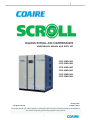
OILLESS SCROLL AIR COMPRESSORS
MAINTENANCE MANUAL AND PARTS LIST
CSOF-S30PL/H32
CSOF-S30PL/H42
CSOF-S40PL/H32
CSOF-S40PL/H42
CSOF-S50PL/H32
CSOF-S50PL/H42
January, 2013
Printed in U.S.A.
All rights reserved
For proper and safe use of the compressor, please follow all instructions and safety precautions as identified in
this manual, along with general safety regulations and practices.
1
WARRANTY
STATEMENT OF WARRANTY TERMS & CONDITIONS
General Provisions:
a) Coaire warrants our air compressors and scroll systems (henceforth called “products”) to be free from material defects and
workmanship under proper use, operating conditions, installation, and application based on the terms and conditions set forth
below. Coaire offers no other warranty, whether expressed or implied, including any warranty of merchantability or fitness for a
particular purpose.
b) Any air compressor, part or material found to be defective will be repaired, replaced or refunded at the sellers option free of charge,
provided that Coaire is notified with the stated warranty period.
c)
All claims shall be made in writing using our warranty claim report located within each service manual.
d) All claims must have the start-up report sheet included. The start-up report sheet is located within each service manual.
e) All returns of allegedly defective equipment must have prior written authorization. Said authorization shall be obtained through our
service department. Any compressors, parts, or materials must be returned freight prepaid to the manufacturers factory within (30)
days of the return authorization date. Any shipment returned to the factory collect will be refused.
f)
If an item is found to be warrantable, the repaired or replacement item will be returned normal ground freight, prepaid. Expedited
return freight costs are the responsibility of the requestor.
g) Any replacement part or material is warranted to the extent of the remaining warranty period
Standard Period of Warranty:
h) Coaire warrants our system(s) for a period of (15) months from shipment, (12) months from the documented start-up, or 5,000
hours of use, whichever occurs first. During such period, Coaire will be liable for all product or material defects and will assume the
costs of repair or replacement so long as the product(s) are located within the continental United States or Canada. In addition, the
product(s) must be easily accessible by service personnel for removal.
i)
In addition to item “g” above, Coaire warrants the air compressor air end (compressor only), parts only (no labor) for a period of (27)
months from shipment, (24) months from the documented start-up, or 7,500 hours of use, whichever occurs first.
j)
Coaire product(s) located outside of the continental United States or Canada shall include a parts only warranty for a period of (15)
months from shipment, (12) months from the documented start-up, or 5,000 hours of use, whichever occurs first.
Exclusions – Coaire shall have no warranty obligation for:
k) Products not installed in accordance with our written instructions and specifications
l)
Operated in an unsuitable environment, in excess of stated product parameters, modified in any way, or used in an improper
manner
m) That have not been properly maintained per Coaire’s written instructions
n) Use of corrosive materials or insoluble lubricants
o) Normal wear and tear items are not included under this warranty
p) Any OEM (original equipment manufacturer) component that may be used within our products will carry the original manufacturer’s
warranty
q) Product is properly stored prior to installation
r)
Product not installed by a competent, qualified installer
s)
Product which may have been damaged during shipment
Liability Limitation:
t)
Coaire shall not be liable for any damages (incidental, consequential, punitive, et al.) that may arise from the use of our product.
Coaire’s liability in all events, is limited to and shall not exceed, the original purchase price.
Suitability of the Product:
u) Jurisdictions has various codes, Coaire makes no claim as to the suitability for all jurisdictions. It is the buyer’s responsibility to
ensure the product, installation, and use comply with local jurisdictions.
Identification plate:
v) Coaire products have identification plates on the air compressors as well as on the enclosures. These data plates show the primary
information for the product. This data should always be referred to when calling the manufacturer or distributor. The removal or
alteration of the identification plate(s) shall immediately void all warranty.
Who to contact for warranty claims:
Web: www.coaire.com
Phone: (562) 496-3935
Fax: (562) 463-4928
8750 Pioneer Blvd., Santa Fe Springs, CA 90670
All freight damage claims should be filed within 15 working days and should be directed to the
carrier.
2
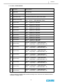
CONTENTS
1.0 Table of Contents
1.0
2.0
3.0
Contents
-------1
7.0
Safety and warnings
2-1 General
-------2
2-2 Safety caution
-------2
2-3 Safety and warnings
-------3
8.0
General
3-1 Specification
-------4
3-2 Major component
-------5
3-3 System diagram
-------7
9.0
Control
7-1 CSOF-S30, 40PL(H) controller
------21
7-2 CSOF-S50PL(H) controller
------29
Maintenance
8-1 Scheduled Maintenance(L)
------36
8-2 Scheduled Maintenance(H)
------37
8-3 Maintenance
------38
Trouble Shooting
------41
10.0 Outline drawings
4.0
5.0
6.0
Installation
10-1 CSOF-S30PL(H)
------45
4-1 Inspection
--------9
10-2 CSOF-S40PL(H)
------46
4-2 Handling
--------9
10-2 CSOF-S50PL(H)
------47
4-3 Installation
------10
4-4 Requirements for the piping
------12
11.0 Electrical wiring drawings
4-5 Wiring
------12
11-1 CSOF-S30PL(H)
------48
11-2 CSOF-S40PL(H)
------50
11-2 CSOF-S50PL(H)
------52
Operation
5-1 Initial Start-up
------15
5-2 Daily operation
------17
Functional description
6-1 Airend
------19
6-2 Motor
------19
6-3 Fan
------20
6-5 Cooler
------20
6-6 Suction Filter
------20
6-7 Check Valve
------20
3
SAFETY AND
WARNINGS
2.0 Safety and warnings
2-1 General
1) The air compressor shall only be operated by a person who has been trained in a safe operation.
2) Please read and be familiar with the user’s manual and the safety instructions before using the air
compressor.
3) The scroll air compressor alone cannot be used for a respiratory system, food and medical equipment
under any circumstance.
4) Do not leave inflammables and explosives near the air compressor.
5) Make sure to use only the genuine Coaire parts. Other types of replacement may cause a serious
failure.
6) The equipment shall safely be operated in compliance with all safety requirements and regulations.
※ The user assumes full responsibility for any problem associated with the non-compliance with the
instructions in the user’s manual.
2-2 Safety Caution
Caution is used to indicate the presence of a hazard which will or can cause
CAUTION
minor personal injury or property damage if the warning is ignored.
Warning is used to indicate the presence of a hazard which can cause severe
WARNING
personal injury, death, or substantial property damage if the warning is
ignored.
Danger is used to indicate the presence of a hazard which will cause severe
DANGER
personal injury, death, or substantial property damage if the warning is
ignored.
Hazardous voltage. Can cause severe injury or death.
Only use factory supplied for incoming power. See Operators/Instruction
manual.
Moving parts. Can cause severe injury.
Do not operate with covers removed.
Service only with machine blocked to prevent turn over.
High pressure air. Can cause severe injury or death.
Relieve pressure before removing filter plugs/caps, fitting or covers.
Please install the product in areas free of explosives (acetylene, propane gas,
etc)or flammable substances. In case of operating the product in flammable
environment, fire or explosion could be caused.
Hot surface. Can cause severe injury.
Do not touch. Allow to cool before servicing.
4
SAFETY AND
WARNINGS
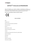
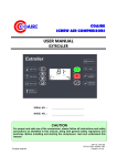
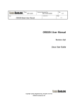
2-3 Safety and Warnings
2-3-1 CSOF-S30PL(H), CSOF-S40PL(H), CSOF-S50PL(H)
DO NOT TOUCH!
HOT SURFACE.
WILL CAUSE INJURY OR
DEATH.
[ 그림 2-1 Front ]
WILL CAUSE INJURY OR
DEATH.
DO NOT TOUCH!
HOT SURFACE.
HIGH PRESSURE. SAFETY
DEPRESSURE THE COMPRESSED AIR.
FLYING PARTS FROM COMPRESSED
AIR CAN CAUSE INJURY OR DEATH.
COMPRESSED AIR FROM THIS MACHINE
CONTAINS OIL MIST WHICH MAY CAUSE
SEVERE NAUSEA, INJURY OR DEATH.
NEVER USE AIR FROM THIS MACHINE
TO SUPPLY BREATHING AIR AND KEEP
UNIT IN A WELL-VENTILATED AREA.
[ 그림 2-2 Side ]
5
GENERAL
3.0 General
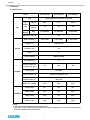
3-1 Specification
Model
CSOF-S30PL(H)
Type
Air
CSOF-S40PL(H)
CSOF-S50PL(H)
Single stage Oil free Scroll Air Compressor
115 psi
84.6
113
141.2
140 psi
72
96
120
Belt
3V-405x12EA
3V-405x16EA
3V-405x20EA
Delivery
UNIT
(cfm)
Driving
Method
High temp. stop (℉)
Output ( kW/HP )
MOTOR
176
3.7/5 x 6SET
3.7/5 x 8SET
Voltage ( V )
208-230, 460
Frequency ( Hz )
60
Poles
4
Starting Method
DIRECT ON LINE
Air Outlet (Inch)
1”
3.7/5 x 10SET
Required minimum
receiver tank (gal)
GENERAL
80
92.5
Cooling Type
Air Cooled
Service air temp. (℉)
Intake air temperature +45
Ambient temp. (℉)
Max. 104
105
Noise Level [dB(A)]
62±5
63±5
65±5
Length (Inch)
63”
63”
63”
Width (Inch)
50.4”
50.4”
50.4”
Height (Inch)
49.6”
64”
80.3”
Weight (Lbs)
1985
2205
2645
DIMENSION
※ Note.
1. Noise level is the measurement from acoustic room.
2. The size is the size of the external design of the package. Protruding areas such as discharge ball valve
have been excluded in the measurement.
6
GENERAL
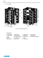
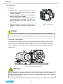
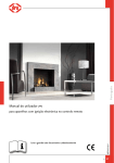
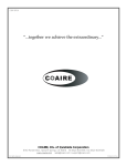
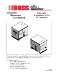
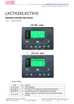
3-2 Major Component
3-2-1 CSOF-S30PL(H), CSOF-S40PL(H)
3
11
6
12
14
10
4
13
15
5
2
18
1
16
8
7
17
9
[ Fig 3-1 ] CSOF-S30PL(H) Outline View
3
11
6
12
14
10
4
15
13
5
2
18
16
8
7
17
1
9
[ Fig 3-2 ] CSOF-S40PL(H) Outline View
#. DESCRIPTION
1. COMMON BASE
6. AIREND PULLEY
11. COOLING FAN
16. SAFETY VALVE
2. COVER & FRAME
7. SUCTION FILTER
12. CONTROLLER
17. DRAIN VALVE
3. AIREND
8. AIR DELIVERY SOCKET
13. CONTROL BOX
18. PRESSURE TRANSMITTER
4. MOTOR
9. AIR DELIVERY PIPE
14. V-BELT
5. MOTOR PULLEY
15. CHECK VALVE
10. AIR COOLER
7
GENERAL
3-2-2 CSOF-S50PL(H)
11
3
6
12
15
14
10
4
5
13
2
1
18
16
8
7
17
9
[ Fig 3-3 ] CSOF-S50PL(H) Outline View
#. DESCRIPTION
1. COMMON BASE
6. AIREND PULLEY
11. COOLING FAN
16. SAFETY VALVE
2. COVER & FRAME
7. SUCTION FILTER
12. CONTROLLER
17. DRAIN VALVE
3. AIREND
8. AIR DELIVERY SOCKET
13. CONTROL BOX
18. PRESSURE TRANSMITTER
4. MOTOR
9. AIR DELIVERY PIPE
14. V-BELT
5. MOTOR PULLEY
15. CHECK VALVE
10. AIR COOLER
8
GENERAL
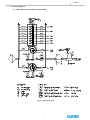
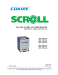
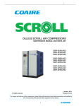
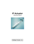
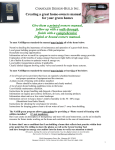
3-3 System Diagram
3--1 CSOF-S30PL(H), CSOF-S40PL(H), CSOF-S50PL(H)
[ Fig.3-4 ] System Diagram
9
GENERAL
CSOF-S SERIES is Oilfree type air compressor. With starting signal, motors start in sequence and
Airend begins to compress air. Air flows from Suction filter to Airend through suction hose.
Compressed air from Airend hits up to 200℃, it passes through check valve(dead end proof) and
Air cooler, the air temperature goes down.
Compressed air contains condensate water, which
should be drain out through drain valve located on Furnish Air Socket. There is Pressure Switch
and Safety Valve sensing pressure of discharged air to protect over pressured air discharging.
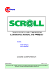
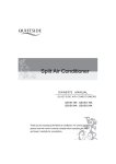
Pressure
Transmitter
Discharge Air
Pipe
Discharge Air
Pipe
Drain Valve
Safety Valve
[Fig 3-5 ] Discharge Air Socket
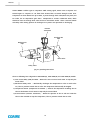
There are following four safeguards in CSOF-S30PL(H), CSOF-S40PL(H) and CSOF-S50PL(H) models:
1) Over Current Relay (OCR) for Motor – Detects the over current of each motor to stop only the
motor failed.
2) Mechanical Safety Valve – Mechanically discharges the compressed air in the air tank to the
air, if the air pressure exceeds the set value. The compressor shall manually be stopped.
3) Temperature Sensor (Temperature Transmitter ) – Detects the temperature exceeding the set
value at the bottom of each airend to stop only the motor failed.
4) Pressure Sensor (Pressure Transmitter ) – Detects the pressure in the air tank and sends the
value to the controller to stop the compressor, if the air pressure exceeds the set value.
10
INSTALLATION
4.0 Installation
4-1 Inspection
When you receive the compressor please inspect it closely.
Upon delivery, carefully check the compressor for damage
during transportation.
If goods are received in damaged condition, it is important
that you notify the carrier and insist on a notation of loss or
damage across the freight bill.
[ Fig.4-1 ] Name plate
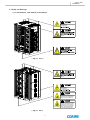
4-2 Handling
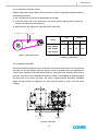
4-2-1 Handling by a forklift
When handling by a forklift, make sure that forks completely extend through the width of the unit.(Fig.4-2)
4-2-2 Handling by a shop crane
When handling
by a shop crane, use the openings provided on common base where slings or steel wire
ropes can be use for lifting. (Fig. 4-3)
[ Fig.4-2 ]
[ Fig.4-3 ]
11
INSTALLATION
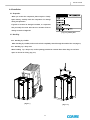
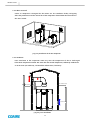
4-3-1 Where to Install
Coaire air compressor is designed for the indoor use. The ventilation facility and piping
affect the performance and the service life of the compressor. Please follow the instructions in
the user’s manual.
[ Fig.4-4 ] Installation of the Air compressor
4-3-2 Ventilation
Poor ventilation in the compressor room may raise the temperature of the air discharged.
If the Room temperature exceeds 18℉ more than the outside temperature, sufficiently ventilate the
air in the room (see Table 4-1), and install the exhaust duct, if necessary.
MIN. 2000mm[78.8"]
MIN. 1000mm[39.4"]
V=MAX.5m/s
MIN. 1500mm[59"]
M
EMERG ENC Y
ST OP
V=MAX. 3m/s
[ Fig.4-5 ] Duct installation
12
INSTALLATION
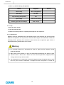
[ Table 4-1 ] Ventilation Fan Capacity
Model
Air Volume
[ ft³/min = CFM ]
Hood Size
[ Inch x Inch ]
CSOF-S30PL(H)
7063
27.55” x 55.1”
CSOF-S40PL(H)
8830
31.5” x 63”
CSOF-S50PL(H)
10595
35.43” x 70.86”
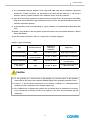
4-3-3 Selection of Where to Install
[table 4-2] Requirements for Where to Install
Item
Description
- Do not install the compressor unit on the outside.
Place
- Please keep warm during the winter season, if you have to install on the
outside.
Space
Floor and
Foundation
Room
Temperature
Hazardous
Substances
Electricity
- Keep the space of more than 31.5inch from the wall to facilitate the repair
and
maintenance of the compressor
- Do not place any object in front of the door.
- The floor shall sufficiently holds the weight of the compressor.
- The floor surface shall be flat with a gradient less than 1 degree to minimize
the vibration.
- It is recommended to install the compressor 4inch above the floor, though
Coaire air compressor generates an insignificant amount of vibration.
- Optimal ambient temperature is 32~104℉ during the operation.
- Install the compressor at low temperature and moisture, if possible.
※ Each 10°C increase of the inlet temperature reduces the efficiency of the
compressor by 3-4%.
- Install the compressor at the place where there is the least noxious gas,
hazardous substance and dust. Those foreign substances may cause the
damage of the air compressor.
- The electric power shall have at least 150% of the reference margin.
- The range of fluctuation in voltage shall be within ±10%.
- A ventilation fan shall be installed to forcedly ventilate the room, if the room
temperature exceeds 10°C more than the outside temperature in the summer.
- For an exhaust duct, set the velocity at 5 m/s, and the static pressure at less
Ventilation
than 5 mmAq.
- Install a protective net on the exhaust outlet to prevent birds, rodents and
foreign substances from entering..
- Place the inlet as low as possible.
13
INSTALLATION
4-4 Requirements for the Piping
1) Use a larger diameter and install the pipe without an excessive bending to reduce the pressure
drop.
1) Always place a branch pipe on the top of a main pipe to reduce the discharge of oil or water.
3)
For the compressed air pipes, reduce the number of sections bending and connecting, and the
number of valves installed to reduce the pressure loss.
4)
The increased pressure loss requires a high discharge pressure of the air compressor.
Consequently, it causes the power loss. The water stays wherever the pipe is sagging to increase
the pipe resistance, which may cause winter-sowing. Thus, consider the pipe straightness when
installing the pipes.
5) Install a bypass piping on each equipment for a maintenance.
6) A scroll air compressor has a check valve in the system. Installing more check valves between the
compressor and the air receiver tank may cause a malfunction of the compressor.
7) Always install a drain valve on the bottom of a vertical pipe for the prevention of a winter-sowing.
4-5 Wiring
1)
Extremely low or high voltage power supply may cause the failure of the compressor. Low power
capacity also causes significant voltage drop when starting up the compressor. The compressor
requires at least 85% of the rated voltage for a start-up, which shall be maintained within ±10% of
the rated voltage during the operation. The inter-phase voltage imbalance shall be within 2%, not
exceeding 3% even in a special case.
2) Features and Capacity
See Table 4-4 Electrical Specification for an appropriate electric power, an operating current and a
starting current. Considering that the discharge air pressure abnormally exceeding the rated
operating pressure increases the operating current, wiring shall allow about 120% of the rated
capacity of a main transformer.
3) See Table 4-4 Electrical Specification for the electric power [kW] and the power factor [%].
4) Minimum Capacity of Transformer [kVA] = {Electric Power [kW] / Power Factor [%]} x 100 x 1.2
5)
Longer lead-in wiring of the main power may cause the compressor failed or tripped during the
start-up due to the voltage drop in the line. Select the thickness of the cable so that it maintains at
least minimum starting voltage.
6) The calculation of the voltage drop based on the line length is as follows:
3-Phase 3-Line Type Connection:
e=
30.8 x L x I
1000 x A
Where,
I = Current [A] A = Cross Section of Cable [mm2]
14
e = Voltage Drop [V]
L = Length of Cable [M]
INSTALLATION
7) It is recommended that the thickness of the cable shall allow more than the minimum requirement
specified for a power condenser, and the length of the cable shall be within 1.5 m. No wiring is
necessary if there is a power condenser with a sufficient capacity in the bus conductor.
8) Leave intact the factory specification of the overcurrent protection device. If the change is unavoidable,
keep the set values within the range specified in the user’s manual. The cable shall allow more than the
minimum requirement specified.
9) As the operating current varies depending on a given condition, it is recommended to allow about 20%
extra.
10) Install a circuit breaker in the main power to protect the motor. The circuit breaker shall have a built-in
electric leak breaker.
11) Use the ground terminal on a motor or a control box to earth the equipment.
[ Table4-3 ] Type of Grounding
Type
Ground Resistance
Thickness of
Grounding
Conductor
Application
1st-Class Grounding
10Ω
2.6 mm2 or above
High Voltage Equipment
2nd-Class Grounding
150Ω/1-Line Ground
Current or below
2.6 mm2 or above
Neutral Point of Transformer
3rd-Class Grounding
100Ω
1.6 mm2 or above
Equipment with Low Voltage
Less than 400 V
Special 3rd-Class
Grounding
10Ω
1.6 mm2 or above
Equipment with Low Voltage
More than 400V
Caution
1) As the grounding on a steel structure of the building may cause the failure of the operation,
always earth on the ground. The maximum allowable length of the grounding conductor is 20 m.
2) If there is a risk of inductive interference on an electronic calculator or a telecommunication
equipment, install a surge killer on the magnetic switch used.
3) The compressor has a complete wiring inside, and no separate wiring or maintenance is necessary.
If any maintenance is needed, see the circuit diagram in the user’s manual provided with the
compressor.
15
INSTALLATION
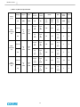
[ Table 4-4 ] Electrical Specification
Voltage
Output
Input
Driving
Current
Starting
Current
[V]
[kW]
[kW]
[A]
[A]
14-13.2
X
6EA
93.8
X
6EA
125
6.6
X
6EA
44.8
X
6EA
60
14-13.2
X
8EA
93.8
X
8EA
250
6.6
X
8EA
44.8
X
8EA
100
14-13.2
X
10EA
93.8
X
10EA
250
6.6
X
10EA
44.8
X
10EA
125
MCCB
OCR
Model
(Poles)
208-230
CSOFS30PL(H)
3.7
X
6EA
(4P)
4.53
X
6EA
460
208-230
CSOFS40PL(H)
3.7
X
8EA
(4P)
4.53
X
8EA
460
208-230
CSOFS50PL(H)
3.7
X
10EA
(4P)
460
4.53
X
10EA
16
AF
TRIP
SET
[A]
[A]
[A]
Main
Power
Cable
AGW
Ground
GV
[㎟]
15.8
125
X
3
6
5
4
2
6
3
4
1/0
16
2
6
6EA
7.9
50
X
6EA
15.8
150
X
8EA
7.9
75
X
8EA
15.8
175
X
10EA
7.9
100
X
10EA
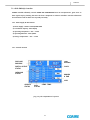
OPERATION
5.0 Operation
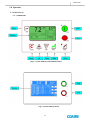
5-1 Initial Start-up
5-1- 1 CONTROLLER
[ Fig 5-1 ] CSOF-S30PL(H), CSOF-S40PL(H) Button
[ Fig 5-2] CSOF-S50PL(H) Button
17
OPERATION
5-1-2 Checklists before the Commissioning
1) Check if the voltage of the main power is within a normal range specified.
2) Cut the main power to connect the power line to the control panel.
3) Check the connection of pipes, a power supply and a grounding.
4) Fully open a stop valve on the discharge pipe of the compressed air.
5-1-3 Commissioning
1) Push the “START” button on the controller to check the direction of rotation. If it is operated in a
negative phase, immediately push the emergency stop button, turn the main power off, and then
convert “R” into “T” before restarting. When the compressor starts, the pressure is increased in
the airend to start the compression.
2) With the discharge valve closed on the discharge side of the air tank, check if the compressor is
automatically stopped, when the pressure reaches the set value.
3) Check if there is any abnormal vibration, noise and leakage.
4) Push the “STOP” button on the controller.
5-2 Routine Operation
5-2-1 Checklists before the Operation
Check the following conditions before starting the operation.
1) Connect the main power to check the display on the monitor.
2) Push the “START” button on the controller to check if the compressor is well started up, and
the indicator lamps are normally on.
3) Check if there is any abnormal vibration, noise and leakage.
4) Check if the operation is in good condition at the maximum load.
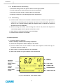
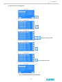
TARET
PRESSURE
DISCHAGE
PRESSURE
COMP. TEMP.
DIGITAL OUTPUT
STATUS
CURRENT TIME
OPERATE
STATUS
ALARM MESSAGE
DIGITAL INPUT
STATUS
COMP. STATUS No.
[ Fig 5-3 ] CSOF-S30PL(H), CSOF-S40PL(H) Display
18
OPERATION
TARET
PRESSURE
DISCHAGE
PRESSURE
CLOCK
DIGITAL OUTPUT
STATUS
OVERLOAD
STATUS
RUNNING
TIME
LOCK
OPERATE
STATUS
RUN
STATUS
COMP. TEMP.
[ Fig 5-4 ] CSOF-S50PL(H) Display
[ Table 5-1 ] Standard Factory settings of control parameters
Model
CSOF-S30PL(H), CSOF-S40PL(H), CSOF-S50PL(H)
Discharge Pressure
psi
115(Low pressure) / 140(High pressure)
Differential Pressure
psi
Discharge Temperature
℉
Item
Stop : 115(Low pressure) / 140(High pressure)
Re-start : 93(Low pressure) / 120(High pressure)
176 ( @ Airend )
Starting Method
D.O.L
5-2-2 Start-Up
1) Check if the tank pressure is 0 psi
2) Check if the monitor indicates a normal condition for the operation, and then push the “START” button.
3) Fully open the valve on the discharge side before starting the compressor.
4) Check if there is any abnormal noise, and the operation is in good condition.
5-2-3 During the Operation
1) With a full load, check the values indicated by the instruments. Also check if the indicator lamps are
normally on in the control panel.
2) Pull the ring on the safety valve every 500 hours to check if the operation is normal.
19
OPERATION
[ Table 5-2 ] Checklists During the Operation
Section
Regulation
Airend Temp.
Max. 176℉(@Airend)
Amb. Temp.
32~104℉
Lamp on during the operation
Sart
Input voltage
±10% of rated voltage
Pressure gap of unit and discharge
Max. 7.25 psi
Re-mark
5-2-4 Stop
1) Push the “STOP” button.
2) Turn the main power off.
3) Check if the internal pressure is completely discharged from the compressor.
5-2-5 Operation Log
Regularly record the information about the operation events in the operation log to early find the
failure of the compressor and to prevent the accident before happens. The information includes the
discharge pressure, operating time, maintenance items and the time to replace the parts. There is a
sample operation log attached in the user’s manual.
Warning
1) It is extremely hazardous to disassemble the valves or pipes from the compressor system
during the operation.
2) Always check if the pressure is 0 psi in the tank before disconnecting the valves or pipes.
3)
Since the tank
is still hot for a certain time even after the operation is stopped, there is
a danger of burns if you are not careful.
4) The rotating parts in the compressor is extremely dangerous during the operation. Do not come
near the parts until the compressor is stopped and the main power is turned off.
20
FUNCTIONAL
DESCRIPTION
6.0 Functional Descriptions
6-1 Airend
An oil free scroll airend is the most important part in the compressor. In any case, the oil is not
entered into the compression chamber. As the inside of the compression chamber is delicate, entering
the dusts or foreign substances results in a serious damage to the compressor. The airend consists of
precision parts, and needs a special jig for a repair and maintenance. It shall only be disassembled by
our qualified engineer or a comparable person.
Housing
Fixed Scroll
Fan Cover
Tip Seal
Sirocco Fan
Orbiting Scroll
[ Fig.6-1 ] Airend parts
6-2 Motor
Some models of the scroll air compressor are equipped with
several motors for an automatic operation based on the amount
of air used. The motor is a 3-phase induction motor that has a
service factor higher than a general motor, and is designed to
generate a high efficiency suitable for an air compressor.
The motor plays an important role for the operation of the air
compressor, and needs maintenance on a regular basis.
[ Fig.6-2 ] Motor
21
FUNCTIONAL
DESCRIPTION
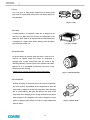
6-3 Fan
Fan is key part to keep proper temperature of airend, please
keep clean and periodically remove dust and foreign object not
to dysfunction.
[ Fig.6-3 ] FAN
6-4 Cooler
A cooler element is an aluminum cooler that is designed to be
used up to 1.5 MPa. Dust may increase the temperature in the
cooler pin, which needs to be cleaned with the compressed air or
a detergent on a regular basis. When cleaning, cover the electric
parts to keep the water out.
[ Fig.6-4 ] COOLER
6-5 Suction Filter
An airend consists of precision parts that need a clean air to be
used for an optimal service life. Coaire air compressor is
equipped with a paper suction filter that has 99.9% of the
dedusting efficiency. The filer needs to be replaced every 20003000 hrs. If it is unavoidable circumstance, the reuse is only
allowed once after cleaning.
※ Make sure to use only the genuine Coaire suction filter.
[ Fig.6-5 ] SUCTION FILTER
6-6 Check Valve
A check valve plays an important role in the scroll air compressor.
The valve prevents the backflow of the compressed air when the
compressor is stopped to protect the compressor from damaging
due to a back-lashing. The valve also protects the wrap of the
compressor from damaging due to foreign substances back flown
from the pipe to the compressor. The valve is designed to stand
against a repetitive pulse motion of scroll at a high temperature
200°C or above.
22
[ Fig 6-6 ] CHECK VALVE
CONTROL
7.0 Control
7-1 CSOF-S30PL(H), CSOF-S40PL(H) Controller
COAIRE controller efficiently controls SCREW AIR COMPRESSOR based on microprocessor, gives users an
alarm against trip by checking the status of the air compressor in advance and offers users the information
for maintenance and let them treat it quickly and easily.
7-1-1 Operating Conditions
1) Power Supply : AC24V ±15% 50/60Hz 40W
2) Transformer Capacity : Min. 50[VA]
3) Operating Temperature : 14℉ ~ 140℉
4) Operating Moisture : 95% @104℉
5) Storage Temperature : -22℉ ~ 176℉
7-2 Major Functions
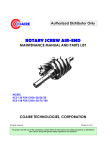
7-2-1 Display
DISCHAGE
PRESSURE
TARET
PRESSURE
DIGITAL OUTPUT
STATUS
COMP. TEMP.
CURRENT TIME
OPERATE
STATUS
ALARM MESSAGE
DIGITAL INPUT
STATUS
COMP. STATUS No.
[ Fig 7-1 ] Display of the Controller
23
CONTROL
7-2-2 Button
[ Fig 7-2 ] Keypad of Controller
[ Table 7-1 ] Description of Keypad
STRAT / STOP
Enter started condition/Exit started condition
RESET
Reset and clear fault condition
MENU
Enter to Menu table
ENTER
Confirm selection of value adjustment
UP / DOWN
CANCEL
Scroll up/down through menu, menu item options
or increment/decrement value
Step back one menu navigation level
24
CONTROL
7-2-3 Status Display Ramp
Operating
Alarm
Green
Regarding the operating status ON / OFF
Red
Regarding the alarm status ON / OFF
7-2-4 Equipment Status Display
1. START/STOP REQUEST SOURCE DISPLAY
LOC : Controller keyboard
NET : Communication request
REM : Digital inputs
2. LOAD REQUEST SOURCE DISPLAY
PRE : Pressure sensor
NET : Communication request (Option)
REM : Digital inputs
3. STOP STATUS DISPLAY
Display while compressor stopped.
LOC STP : Stopped by controller keyboard
REM STP : Stopped by digital inputs
NET STP : Stopped by communication request (Option)
S.D STP : Stopped by fault condition
4. START STATUS DISPLAY
Display while compressor started.
LOC RUN : Started by controller keyboard
REM RUN : Started by digital inputs
NET RUN : Started by communication request (Option)
5. COMPRESSOR STATUS DISPLAY
GOOD : Normal conditon
MAINTEN : Maintenance required
ALARM : Alarm condition
S-DOWN : Trip condition
INHIBIT : Start inhibit condition
25
CONTROL
7-2-5 System Locked
SYSTEM LOCKED SYMBOL
7-2-6 Digital Input Symbols
Symbol
Description
Symbol
Description
OC1
Over current Motor #1
OC6
Over current Motor #6
OC2
Over current Motor #2
OC7
Over current Motor #7
OC3
Over current Motor #3
OC8
Over current Motor #8
OC4
Over current Motor #4
EMS
Emergency Switch
OC5
Over current Motor #5
RET
Remote Start/Stop Control
7-2-7 Digital Output Symbols
Symbol
Description
Symbol
Description
C1
Comp #1 On/Off Control
C7
Comp #7 On/Off Control
C2
Comp #2 On/Off Control
C8
Comp #8 On/Off Control
C3
Comp #3 On/Off Control
N9
Multi Function Port N9
C4
Comp #4 On/Off Control
N10
Multi Function Port N10
C5
Comp #5 On/Off Control
N11
Multi Function Port N11
C6
Comp #6 On/Off Control
N12
Multi Function Port N12
26
CONTROL
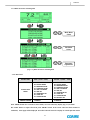
7-2-8 Menu Structure and Navigation
Main Menu
Select
Sub Menu
Select
Parameter
Adjustment
[ Fig. 7-3 ] Menu Structure and Navigation
7-2-9 Menu level
ACCESS LEVEL
USER (CODE = 0000)
SERVICE 1 (CODE = 0100)
ACCESS-ABLE
MENU
00.
01.
02.
03.
04.
05.
06.
07.
00.
01.
02.
03.
04.
05.
06.
07.
08.
TIMEOUT PERIOD
STATUS MODE
PRESSURE MODE
SCHEDULE MODE
TRIP LOG MODE
TRIP SET
OPERATION SET
COMP SET
CONFIG MODE
1 MINUTE
STATUS MODE
PRESSURE MODE
SCHEDULE MODE
TRIP LOG MODE
TRIP SET
OPERATION SET
COMP SET
CONFIG MODE
FACTORY SET
10 MINUTE
Press “MENU” button for a seconds in status mode, an access code entry display (Fig. 7-4) is shown.
Use “PLUS” button to adjust value then press “ENTER“ button. If the access code have been entered to
authorized, menu page will be displayed. An invalid code will return the display to normal operation mode.
27
CONTROL
[ Fig. 7-4 ] ACCESS CODE ENTRY DISPLAY
NOTE
1) When access level is “SERVICE 1”, [Equipment Environment Setup] menu cannot be adjusted.
2) Press “CANCEL” button for three seconds at any time to return to the system locked condition.
7-2-10 Digital Output
ACCESS CODE ( 0100 )
M
E
N
U
S
1. . STATUS MODE
Editable
×
2. . PRESSURE MODE
- TARGET PRESSURE
○
- STEP#1~STEP#8 RUNPRESS
×
- STEP#1~STEP#8 STOPPRESS
×
- LCD LIGHT MODE
×
3. SCHEDULE MODE
×
4. TRIP LOG MODE
×
5. TRIP SET
×
6. OPERATION SET
×
7. COMP SET
×
8. CONFIG MODE
×
T
R
U
C
T
U
R
E
28
CONTROL
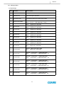
7-2-11 TRIP / ALARM MESSAGE
Item
Description
Detect condition
1
System Error
Parameter Error
2
Emergency stop
Push the emergency stop switch
3
Press. Sensor Fault
Low Resistance, Short Circuit, Short Circuit to Earth
4
Delivery Pressure High
Detection Pressure >= [ DIS. PRESS LIMIT]
Reset
Pressure < [ DIS. PRESS LIMIT -7.25psi]
5
Comp #1 Fault
Detection [Digital Input :ID1 ] OPEN
Reset
[Digital Input : ID1] CLOSE
6
Comp #2 Fault
Detection [Digital Input :ID2 ] OPEN
Reset
[Digital Input : ID2] CLOSE
7
Comp #3 Fault
Detection [Digital Input :ID3 ] OPEN
Reset
[Digital Input : ID3] CLOSE
8
Comp #4 Fault
Detection [Digital Input :ID4 ] OPEN
Reset
[Digital Input : ID4] CLOSE
9
Comp #5 Fault
Detection [Digital Input :ID5 ] OPEN
Reset
[Digital Input : ID5] CLOSE
10
Comp #6 Fault
Detection [Digital Input :ID6 ] OPEN
Reset
[Digital Input : ID6] CLOSE
11
Comp #7 Fault
Detection [Digital Input :ID7 ] OPEN
Reset
[Digital Input : ID7] CLOSE
12
Comp #8 Fault
Detection [Digital Input :ID8 ] OPEN
Reset
[Digital Input : ID8] CLOSE
13
Comp #1 Temp.
Detection Comp#1 Temp. >= [COMP TEMP LIMIT]
Reset
Comp#1 Temp. >= [COMP TEMP LIMIT] -9℉
14
Comp #2 Temp.
Detection Comp#2 Temp. >= [COMP TEMP LIMIT]
Reset
Comp#2 Temp. >= [COMP TEMP LIMIT] -9℉
15
Comp #3 Temp.
Detection Comp#3 Temp. >= [COMP TEMP LIMIT]
Reset
Comp#3 Temp. >= [COMP TEMP LIMIT] -9℉
16
Comp #4 Temp.
Detection Comp#4 Temp. >= [COMP TEMP LIMIT]
Reset
Comp#4 Temp. >= [COMP TEMP LIMIT] -9℉
17
Comp #5 Temp.
Detection Comp#5 Temp. >= [COMP TEMP LIMIT]
Reset
Comp#5 Temp. >= [COMP TEMP LIMIT] -9℉
18
Comp #6 Temp.
Detection Comp#6 Temp. >= [COMP TEMP LIMIT]
Reset
Comp#6 Temp. >= [COMP TEMP LIMIT] -9℉
19
Comp #7 Temp.
Detection Comp#7 Temp. >= [COMP TEMP LIMIT]
Reset
Comp#7 Temp. >= [COMP TEMP LIMIT -9℉
20
Comp #8 Temp.
Detection Comp#8 Temp. >= [COMP TEMP LIMIT]
Reset
Comp#8 Temp. >= [COMP TEMP LIMIT] -9℉
※ An trip message is displayed that must be manually reset to clear once the condition has been
resolved or no longer exists.
29
CONTROL
7-2-12 ALARM CONDITION
Item
1
Description
RTC(Real Time Clock)
Alarm
Detect condition
Detection RTC Disable (When Schedule Mode Operation)
Reset RTC Enable
※ An trip message is displayed that will be automatically reset to clear once the condition
has been resolved.
7-2-13 EVENT MESSAGE for OPERATION INFORMATION
Item
Description
Detect condition
1
1’ST POWER
The time when Initial Power UP to Controller.
2
POWER UP
The time when power up to controller
System restoration by watchdog timer
3
START
The time when motor started.
4
STOP
The time when motor stopped.
30
CONTROL
7-3 CSOF-S50PL(H) Controller
COAIRE controller efficiently controls SCREW AIR COMPRESSOR based on microprocessor, gives users an
alarm against trip by checking the status of the air compressor in advance and offers users the information
for maintenance and let them treat it quickly and easily.
7-3-1 Power Supply & Environment
1) Power Supply : AC24V ±15% 50/60Hz 40W
2) Transformer Capacity : Min. 50[VA]
3) Operating Temperature : 14℉ ~ 140℉
4) Operating Moisture : 95% @104℉
5) Storage Temperature : -22℉ ~ 176℉
7-3-2 General Function
DISCHAGE
PRESSURE
TARET
PRESSURE
DIGITAL OUTPUT
STATUS
CLOCK
OVERLOAD
STATUS
RUNNIN
G TIME
LOCK
OPERATE
STATUS
RUN
STATUS
COMP. TEMP.
[ Fig 7-5 ] The composition of a picture
31
CONTROL
7-3-3 Set function
[ Fig 7-6 ] Button
Pressing this button, unit will start or stop.
Start/Stop
START
Reset
STOP
This button is used to reset when unit has alarm.
Menu
Pressing this button will change the information
selected for the display.
Next
To the next page
[ Table 7-2 ] Function of push button
32
CONTROL
7-3-4 Menu Structure and Navigation
Using set working pressure
To the change basic menu
[ Fig. 7-7 ] MENU STRUCTURE and NAVIGATION
33
CONTROL
7-3-5 Using menu level
Press “MENU” button for a seconds in status mode, an access code entry display (Fig. 7-8) is shown.
Use“PLUS” button to adjust value then press “ENTER“ button. If the access code have been entered to
authorized, menu page will be displayed. An invalid code will return the display to normal operation
mode.
[ Fig 7-8 ] Using code input
NOTE
1) When access level is “SERVICE 1”, [Equipment Environment Setup] menu cannot be adjusted.
2) Press “CANCEL” button for three seconds at any time to return to the system locked condition.
7-3-6 Digital Output
ACCESS CODE ( 0100 )
M
E
N
U
S
1. . STATUS MODE
Adjust
×
2. . PRESSURE MODE
- TARGET PRESSURE
○
- STEP#1~STEP#10 RUNPRESS
×
- STEP#1~STEP#10 STOPPRESS
×
- LCD LIGHT MODE
×
T
R
3. SCHEDULE MODE
×
U
4. TRIP LOG MODE
×
5. TRIP SET
×
6. OPERATION SET
×
7. COMP SET
×
8. CONFIG MODE
×
C
T
U
R
E
34
CONTROL
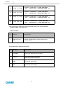
7-3-7 Message output
1) Trip message
Item
Description
Detect condition
1
System Error
Parameter Error
2
Emergency stop
Push the emergency stop switch
3
Press. Sensor Fault
Low Resistance, Short Circuit, Short Circuit to Earth
4
Delivery Pressure High
Detection Pressure >= [ DIS. PRESS LIMIT]
Reset
Pressure < [ DIS. PRESS LIMIT -7.25psi]
5
Comp #1 Fault
Detection [Digital Input :ID1 ] OPEN
Reset
[Digital Input : ID1] CLOSE
6
Comp #2 Fault
Detection [Digital Input :ID2 ] OPEN
Reset
[Digital Input : ID2] CLOSE
7
Comp #3 Fault
Detection [Digital Input :ID3 ] OPEN
Reset
[Digital Input : ID3] CLOSE
8
Comp #4 Fault
Detection [Digital Input :ID4 ] OPEN
Reset
[Digital Input : ID4] CLOSE
9
Comp #5 Fault
Detection [Digital Input :ID5 ] OPEN
Reset
[Digital Input : ID5] CLOSE
10
Comp #6 Fault
Detection [Digital Input :ID6 ] OPEN
Reset
[Digital Input : ID6] CLOSE
11
Comp #7 Fault
Detection [Digital Input :ID7 ] OPEN
Reset
[Digital Input : ID7] CLOSE
12
Comp #8 Fault
Detection [Digital Input :ID8 ] OPEN
Reset
[Digital Input : ID8] CLOSE
13
Comp #9 Fault
Detection [Digital Input :ID9 ] OPEN
Reset
[Digital Input : ID9] CLOSE
14
Comp #10 Fault
Detection [Digital Input :ID10 ] OPEN
Reset
[Digital Input : ID10] CLOSE
15
Comp #1 Temp.
Detection Comp#1 Temp. >= [COMP TEMP LIMIT]
Reset
Comp#1 Temp. >= [COMP TEMP LIMIT] -9℉
16
Comp #2 Temp.
Detection Comp#2 Temp. >= [COMP TEMP LIMIT]
Reset
Comp#2 Temp. >= [COMP TEMP LIMIT] -9℉
17
Comp #3 Temp.
Detection Comp#3 Temp. >= [COMP TEMP LIMIT]
Reset
Comp#3 Temp. >= [COMP TEMP LIMIT] -9℉
18
Comp #4 Temp.
Detection Comp#4Temp. >= [COMP TEMP LIMIT]
Reset
Comp#4 Temp. >= [COMP TEMP LIMIT] -9℉
19
Comp #5 Temp.
Detection Comp#5 Temp. >= [COMP TEMP LIMIT]
Reset
Comp#5 Temp. >= [COMP TEMP LIMIT] -9℉
20
Comp #6 Temp.
Detection Comp#6 Temp. >= [COMP TEMP LIMIT]
Reset
Comp#6 Temp. >= [COMP TEMP LIMI -9℉
35
CONTROL
21
Comp #7
Temp
Detection Comp#7 Temp. >= [COMP TEMP LIMIT]
Reset
Comp#7 Temp. >= [COMP TEMP LIMIT] -9℉
22
Comp #8
Temp
Detection Comp#8 Temp. >= [COMP TEMP LIMIT]
Reset
Comp#8 Temp. >= [COMP TEMP LIMIT] -9℉
23
Comp #9
Temp
Detection Comp#9 Temp. >= [COMP TEMP LIMIT]
Reset
Comp#9 Temp. >= [COMP TEMP LIMIT] -9℉
24
Comp #10 Temp
Detection Comp#10 Temp. >= [COMP TEMP LIMIT]
Reset
Comp#10 Temp. >= [COMP TEMP LIMIT] -9℉
※ An trip message is displayed that must be manually reset to clear once the condition
has been resolved or no longer exists.
2) Alarm Condition
Item
Description
RTC(Real Time Clock)
Alarm
1
Detect condition
Detection RTC Disable (When Schedule Mode Operation)
Reset RTC Enable
3) Event Message for Operation Information
Item
Description
Detect condition
1
1’ST POWER
The time when Initial Power UP to Controller.
2
POWER UP
The time when power up to controller
System restoration by watchdog timer
3
START
The time when motor started.
4
STOP
The time when motor stopped.
36
CONTROL
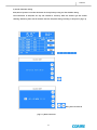
4) System date/time setting
Date/time of system is used that the datum of the trip history saving and the schedule driving.
The information of date/time for trip and schedule is necessary when the machine get the trouble
shooting. therefore, please use the machine after the date/time setting according to the picture [ Fig 7-9]
Using date and time set
[ Fig 7-9 ] Date & Time Set
37
MAINTENANCE
8.0 Maintenance
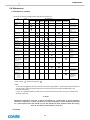
8-1 Maintenance schedule
Low pressure (115 psi) and high pressure (140 psi) scroll enclosures
Item
action
Every Day
Condensate drain
drain
Enclosure
ventilation fan
check
Control panel
check
Belt
(consult factory for
the correct belt)
Safety relief valve
Remarks
5,000 hours
or 2 years
10,000 hours
or 4 years
(1st time)
After cooler
Clean
Replace as needed
based on filter
condition
Clean more often if
necessary
Clean
Check,
Replace
Check
Temperature sensor
#520-101-08
Check
operation
Pressure sensor
#520-109-04
Check
operation
Motor
(consult factory for
motor part number
and pricing)
Motor pulley
(consult factory for
motor part number
and pricing)
Intake suction hose
#520-139-00
Grease bearings
(3) crank bearings
(1) main bearing
#BC5KL-PK2
Tip seal Kit
Kit #BC5KL(H)-06
Tip seals
Back up tube
Dust seal
Check
insulation,
bearing
Check or Clean
Run Time (Hours)
1,250
2,500 hours
hours
or 1 year
Check,
replace
Inlet air filter
#BC5KL-RK1
Discharge check
valve
#520-109-02
System piping
500
hours
Ensure after cooler
and compressor fan
are clear of debris
Check the monitor
for maintenance or
alarms
Tighten or replace
as needed
Check
operation
Clean,
replace
Air end sirocco fan
250
hours
Check for leaks /
tightness
Replace if not
functioning
properly
Replace if not
functioning
properly
check
Check the pulley
grooves for wear
Check,
replace
grease
** high pressure
scrolls need grease
every 5,000 hours
Replace
** high pressure
scrolls need tip
seal change every
5,000 hours
Replace or Re-grease
Notes:
1.) The intervals suggested above are based on normal operating conditions - ambient temperature between 35°
and 104°F and a clean environment. Maintenance intervals may need to be shortened depending on the
operating environment.
2.) User, or a qualified technician, should carry out the maintenance based on the run hours or calendar time,
whichever comes first
※ NOTE
Maintenance schedule is instructed as above. The intervals are a guide based on normal operating
conditions. If operated in a severe environment, necessary maintenance service should be performed
on a more frequent basis. User should carry out the maintenance work, based on either the running
hours or the calendar time whichever comes first.
8-2 (blank)
38
MAINTENANCE
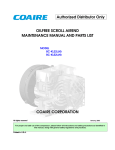
8-3 Maintenance
8-3-1 Airend
1) Check if there is any abnormal vibration or noise
during a routine operation, and contact the nearest
distributor, if necessary.
2) There are two types of the scroll airend: Low Pressure
(115psi) and High Pressure (140psi).
The maintenance period is different by type specified
in the identification plate attached on an airend. The
standard specification of Coaire airend is a low
pressure type.
3) Periodically lubricate an airend with grease. See the
maintenance schedule for when the lubrication is
needed.
[ Fig.8-1 ] Scroll Airend
Caution
The airend consists of precision parts, and needs special tool and jig for a repair and maintenance.
It shall only be disassembled by our qualified engineer. Contact the nearest distributor, if necessary.
8-3-2 Rotation of the Driving Part
If the motor is not started up or generates an abnormal noise, stop the compressor, turn the main
power off, and then manually rotate the motor pulley. If it does not rotate smoothly, contact the
nearest distributor for a service. It is mostly due to the damage on the motor bearing or when the
airend is stuck.
[ Fig. 8-2 ] Motor Airend connection
Warning
An air compressor is automatically operated. Do not come near the parts until the compressor is
stopped and the main power is turned off. It may cause a serious personal injury, if hair or clothes is
caught in the rotating parts.
39
MAINTENANCE
8-3-3 Adjustment of the Belt Tension
Adjust the belt tension in first 500 hrs after the purchase, and every 3,000 hrs(6 months) thereafter in
the following procedures.
1) Use a tensionmeter to measure the displacement of each belt.
2)
Loose the anchor bolt on the motor base, and use the tension adjusting bolt to adjust the
tension with reference to the [Table 8-1].
3) Align the motor, and tighten the anchor bolt on the motor base.
Looseness = δ [in]
P [ kg ]
New
Displace
Model
P kg
δm
P kg
δmm
1.7
0.24
1.6
0.23
CSOF-S30PL(H)
CSOF-S40PL(H)
CSOF-S50PL(H)
[ Fig8-3 ] Belt tension check
[ Table 8-1 ] Belt tension
8-3-4 Alignment of the Belt
Off-centered pulleys generate the noise and vibration, and accelerate the process of wearing the belt
and pulley to cause the damage to the belt. Align the center of the pulley during the replacement of
a belt and the adjustment of the belt tension. With the compressor fixed, loose the anchor bolt on
the motor, and place an iron rule between the pulleys as shown in the following fig. Gradually tighten
the anchor bolt on the motor and check
the center is aligned between the pulleys. Completely
tighten the bolt, recheck the alignment, and then rotate the pulley to check if the belt moves
Below 0.04in
smoothly.
ADJUSTED SIDE
FIXED SIDE
MOTOR
AIREND
[ Fig.8-4 ] Belt align
40
MAINTENANCE
Caution
1) An air compressor is automatically operated. Do not check and replace the belt until the
compressor is stopped and the main power is turned off.
2) Only use the belt specified by Coaire for a replacement. Do not use old and new belts mixed, and
replace the entire set of belts all at once.
3) The shaft is damaged and the service life of the bearing is shorten at a high tension of the belt,
while the belt is slippery at a low tension of the belt. Always keep the optimal tension value with
reference to the [Table 8-1].
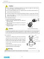
8-3-5 Cleaning the Suction Filter
1) Check the contamination level every 500 hrs.
2) Replace the heavily contaminated filter even before the
replacement period.
3)
Blow the element with the compressed air outward, and
then by the side.
4) Keep dust and foreign substances out of the compressor
during the assembly.
Caution
[ Fig.8-5 ] Suction filter cleaning
A suction filter significantly affects the service life of an airend. Make sure to use only the genuine
Coaire suction filter. Coaire cannot be responsible for any damage caused by an improper replacement.
8-3-6 Check valve
CAP
Compressed air leakage may come from suction filter
SPRING
originated form check valve leakage. In severe case, airend
SEAT
backlash occurred. This case may cause severe damage to
airend because of foreign objects from outside. To prevent
VALVE BODY
possible defect, check Check-Valve every 2,500hours
1) Screw CAP open .
2) Check spring tension and SEAT of Check valve
3) Replace valve when it has been damaged.
[ Fig. 8-6 ] Check valve
Warning
Be sure of 0MPa of air pressure. It may cause injuries or severe damages
41
TROUBLESHOOTING
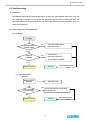
9.0 Troubleshooting
9-1 Overview
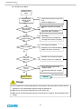
The following flow diagrams show the procedures to repair the typical failures. If the alarm is on and
the compressor is stopped, do not restart the operation until the cause is clearly addressed and
eliminated. Always turn the main power off, and remove the pressure from the compressor prior to a
repair and maintenance.
9-2 Flow diagram for Troubleshooting
9-2-1 No Display
No Display
Poor connection
to power supply
Yes
- Check the breaker switch
- Check the wiring
No
Failure of
controller
- Check the fuse
Yes
- Check the transformer
- The controller is defective
No
After eliminating the
Request a service
Start-Up
cause
9-2- 2 Negative-Phase
Operation
Negative-phase
operation
Abnormal noise
Yes
Poor connection
to power supply
Convert the phase for two of three
main power lines.
No
Start-Up
Request a service
42
After eliminating the
cause
TROUBLESHOOTING
9-2-3 Unable to Start Motor
Unable to start
motor
Check the error
message on the
controller
No
Lead-in wiring is
disconnected
Yes
- Check the tripping error
Yes
- Check the resistance of incoming
line
- Test wiring and cable capacity, and
replace the cable, if necessary
No
Failure of
magnetic switch
- Take necessary action to correct the
error
Yes
- Test wiring
- Check the contact and operation,
and replace the switch, if necessary
No
Yes
Failure of motor
- Test wiring and resistance
- Manually turn to check the bearing
- Replace the motor, if necessary
No
Failure of
compressor
Yes
- Manually turn to check the rotation
- Request a service if it is defective
No
Failure of
controller
No
Yes
- Check the output signal of the
magnetic switch
- Turn the main power off, and then
on
After eliminating the cause
Request a service
Start-Up
Danger
1) An air compressor is automatically operated. Take necessary safety precaution to ensure that the
compressor is not unintentionally operated during the maintenance.
2) Make sure to turn the main power off prior to the rotation test.
3) Make sure to turn the main power off prior to the wiring test, except for the measurement of the
voltage.
43
TROUBLESHOOTING
9-2-4 No Compression
Low discharge
pressure
Excessive amount
of air used
Yes
- Install an additional compressor if
the capacity is insufficient
No
Suction filter is
clogged
- Check the pipe for leakage
Yes
- Clean the suction filter, and replace,
if necessary
No
Airend is
damaged
Yes
- Check the rotation
- Check if there is any abnormal noise
No
Failure of
controller
Yes
- Check the function of a multi-unit
control
- Check the magnet and the output of
the controller
No
After eliminating the cause
Start-Up
Request a service
9-2-5 Discharge Pressure Rise
Error message
“Delivery Pressure High” appears
Discharge Pressure Rise
Safety valve is
activated
Yes
Pressure sensor or safety valve is
defective
No
Yes
Check the operation of the pressure
sensor
Failure of pressure
sensor
No
Yes
Failure of controller
Check the output of the controller
No
After eliminating the cause
Request a service
Start-Up
44
TROUBLESHOOTING
9-2-6 Discharge Temperature Rise
Error message
“comp #1~#10 temp” appears
Discharge temperature rise
High ambient
temperature
Yes
- Keep the internal temperature 40°C
or below
- Check the ventilation facility and
duct
No
Check the
controller
Yes
- Check the input/out of the
temperature sensor
- Replace the temperature sensor, if
necessary
No
After eliminating the cause
Request a service
Start-Up
Notes:
1) An appropriate temperature of an airend is 70°C or below at the operating temperature 104℉
or below.
2) Always take necessary action if the temperature of the airend is sharply increased with no
change in ambient temperature.
9-3 Other Troubleshooting
Trouble
1. Tripped due to
Cause
Action
1) Compressor is tripped.
1) Contact the distributor.
the overcurrent
- Foreign substance in the compressor
in motor
- Damage to the wrap of the compressor
- Low voltage
2. Noise and
Vibration
- Improve the power supply.
2) Open-phase/Unbalanced power supply
2) Improve the power supply.
3) Deteriorated coil in the motor
3) Check the motor.
4) Failure of EOCR
4) Readjust or replace.
1) Fixing bolts are loose.
1) Readjust.
2) Noise from the compressor
2) Contact the distributor.
- Bearing is worn out or damaged.
- Foreign substance in the compressor
3) Improper belt tension and the damage to
3) Realign or replace the belt.
the parts
4) Inadequate installation of the compressor
4) Reinstall the compressor.
5) Failure of cooling fan (dust or damaged)
5) Clean or replace the fan.
45
OUTLINE DRAWINGS
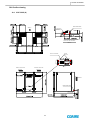
10.0 Outline drawing
10-1 CSOF-S30PL(H)
MAIN POWER INLET
VIEW "A"
AIR OUTLET
25A (1")
DETAIL FOR AIR DISCHARGE
VIEW "A"
Ground
Main terminal block
R S T
EXHAUST AIR OUTLET
EXHAUST AIR OUTLET
EMERGENCY
STOP
AIR INTLET
MAIN POWER INLET
AIR OUTLET
46
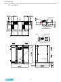
OUTLINE DRAWINGS
10-2 CSOF-S40PL(H)
MAIN POWER INLET
VIEW "A"
AIR OUTLET
25A (1")
DETAIL FOR AIR DISCHARGE
VIEW "A"
Main terminal block
Ground
R S T
EXHAUST AIR OUTLET
EXHAUST AIR OUTLET
AIR INTLET
EMERGENCY
STOP
AIR INTLET
MAIN POWER INLET
AIR OUTLET
47
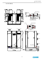
OUTLINE DRAWINGS
10-3 CSOF-S50PL(H)
VIEW "A"
MAIN POWER INLET
AIR OUTLET
25A (1")
토 출 공 기 구
DETAIL FOR AIR DISCHARGE
VIEW "A"
Main terminal block
Ground
R S T
EXHAUST AIR OUTLET
EXHAUST AIR OUTLET
AIR INTLET
EMER GENCY
STOP
AIR INTLET
AIR INTLET
MAIN POWER INLET
AIR OUTLET
48
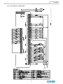
ELECTRICAL WIRING
DRAWINGS
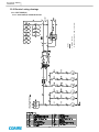
11.0 Electrical wiring drawings
11-1 CSOF-S30PL(H)
(T상)
(R상)
49
B: BLACK, BL: BLUE, R: RED, Y: YELLOW
1. WIRING COLOR
NOTES
11-1-1 CSOF-S30PL(H) POWER & MOTOR
ELECTRICAL WIRING
DRAWINGS
50
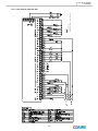
B: BLACK, BL: BLUE, R: RED, Y: YELLOW
1. WIRING COLOR
NOTES
11-1-2 CSOF-S30PL(H) CONTROL LINE
ELECTRICAL WIRING
DRAWINGS
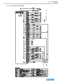
11-2 CSOF-S40PL(H)
51
B: BLACK, BL: BLUE, R: RED, Y: YELLOW
1. WIRING COLOR
NOTES
11-2-1 CSOF-S40PL(H) POWER & MOTOR
ELECTRICAL WIRING
DRAWINGS
52
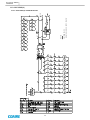
B: BLACK, BL: BLUE, R: RED, Y: YELLOW
1. WIRING COLOR
NOTES
11-2-2 CSOF-S40PL(H) CONTROL LINE
ELECTRICAL WIRING
DRAWINGS
11-3 CSOF-S50PL(H)
53
B: BLACK, BL: BLUE, R: RED, Y: YELLOW
1. WIRING COLOR
NOTES
11-3-1 CSOF-S50PL(H) POWER & MOTOR
ELECTRICAL WIRING
DRAWINGS
NOTES
54
1. WIRING COLOR -
B: BLACK, BL: BLUE, R: RED, Y: YELLOW
11-3-2 CSOF-S50PL(H) CONTROL LINE
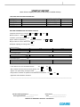
STARTUP REPORT
Please fill out completely and return to the factory to validate warranty.
CUSTOMER AND MACHINE INFORMATION
CUSTOMER
ADDRESS
CITY/STATE
PHONE
WRITTTEN BY
FACTORY SHIP DATE
DATE STARTED UP
MODEL NUMBER
SERIAL NUMBER
HOURS ON MACHINE
/
/
/
/
Hrs.
MACHINE INFORMATIONS AND INITIAL STARTUP
Compressor Environment- excellent
Machine Location – indoors
, good
, fair
, poor
.
outdoors
if outdoors, protected from rain? Yes
No
.
Approx. ambient temperature______ adequate ventilation? - Yes
Did you check for correct rotation? Yes
No
.
No
Nameplate amperage for voltage used ______
Incoming Voltages
L1-L2
L2-L3
L1-L3
Volts
Volts
Full load amperage at _________ PSIG
L1
Amp.
L2
Unload amperage at _________ PSIG
L1
Amp.
L2
Is the machine on a level and stable surface?
Volts
L3
Amp.
Amp.
L3
Amp.
Yes
Was a flexible connector used to connect piping? – Yes
No
No
Amp.
.
.
Approx. time spent during startup procedure ___________ Hrs.
Did you advice customer on operation and maintenance of machine? Yes
No
.
Application and installation comments:
___________________________________________________________________________________________________
Machine Sold By(Company) __________________
Startup performed by _______________
Sales Person ___________________________
Date _________________________________
THERE IS NO WARRANTY WITHOUT THIS REPORT!
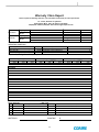
55
Warranty Claim Report
Please complete the following claim form, your claim will be confirmed by our sales representative.
To : Coaire, Division of Quietside
8750 Pioneer Blvd., Santa Fe Springs, CA 90670
Tel(562)576-1330.Fax(562)699-4351 email: support@coaire.com
Date
Model
Serial No.
Run Hours
Setting Press.
Company
Distributor
Address
Company
Customer
Address
Hrs.
PSIG
OPERATING CONDITIONS
Percent(%) on load
No. of days of operation weekly
Hours per day
Machine setting OL/OL or Mod
%
Days
Hours
Ambient Temperature
Discharge temperature
Compressor area temperature
Environment 1)
·F
·F
·F
1) 1 to 10, 1 being clean, 10 very dirty
Incoming Voltages
L1 - L2
L2 - L3
Volts
Volts
L1 - L3
Volts
Full load amperage at _______ PSIG
L1 - L2
L2 - L3
L1 - L3
Amp.
Amp.
Amp.
Unload amperage at ______ PSIG
L1 - L2
L2 - L3
L1 - L3
Amp.
Amp.
Amp.
Symptom
Fault Diagnosis
Resolution
Parts required
No. Item Number
01
02
03
04
WRITTEN BY
Labor Cost
Description/MFGR Part Number
Quantity
Labor Time: Hrs x
Travel Time: Hrs x
Total Amount:
Technician’s name:
SIGNATURE
56
X
$/Hrs= $
$/Hrs= $
QUALITY AND RELIABILITY
WITHOUT COMPROMISE
COAIRE reserves the right to make changes, at any time without notice as a result of our commitment to
continuous improvement.
57