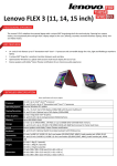
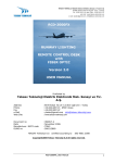
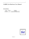
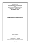
1
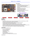
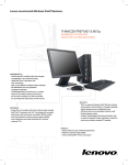
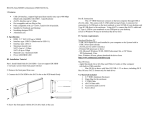
T1100
Book Size PC
Assembly Guide
BCM Advanced Research
Chapter 1 Introduction
The T-1100 (Fig.1) is a high-performance book-sized PC with the revolutionary
features of small size and light weight. It not only can be used in the office, but also a
great choice for SOHO users or PC players. Inside this elegant-designed case, it has a
powerful motherboard that has all the functions a user needs.
This Assembly Guide will help a user understand the components of T-1100 and
lead a user to assemble the system with detailed steps and instructions.
The T-1100 will perform perfectly once the system is assembled correctly.
1-1 Package Content (Fig.2)
1. Power cord
7 T-1100
2. CD driver
8 User’ manual
3. CPU fan heatsink
4. A set of screws
9 Assembly guide
5. Mat rubber foot
6. Foot stand
1-2 Description of The Structure
Specification
Description
Processor
Socket 370 for Intel Pentium II/ III, Celeron PPGA/
FCPGA processor, optimized for F.S.B 66/ 100/ 133 MHz
System memory
Support 2 banks of SDRAM up to 1GB
Hard Disk
Support Slim 2.5" HDD
Dimension
62mm(H) x 272mm(W) x 252mm(D)
Weight
3.0 ±0.5kg
Power specification
AC100~240V(50/ 60Hz)
Power supply Spec.
DC output 150W MAX (Bona: PS001)
1-3 Description of The Case
Front Panel (Fig. 3)
1. Slim CD-ROM (Optional. You can choose to install slim DVD-ROM, slim
CD-RW or nothing, as you like)
Fig.3
2. Power switch
3. 1xIEEE 1394 port
4. 2xUSB ports
5. Network LED
6. HDD LED
7. Power LED
8. Reset switch
1-4 Back Panel (Fig. 4)
Fig.4
1.
2.
3.
4.
PS/2 mouse connector
2 RJ45 Jack for network
3-1xParallel port
4 2xSerial ports
5.
6.
7.
8.
Power connector
Power voltage setting
Power supply
PS/2 keyboard connector
9. 2xUSB ports
10. VGA connector
11. 1xIEEE 1394 port
12. Audio speaker/ Line in/ Line out Jacks
1-5
Description of Layout and Component
Components (Fig. 5)
1. Power supply
2. CD-ROM cable
3.
4.
5.
6.
HDD cable
Power/ Audio cable
IEEE 1394+ USB cable
Motherboard
7. System fan
8. Serial port cable
Enlarged view of the system (Fig. 6)
Chapter 2
Assembly Procedure
Attention!
This procedure is for the users who choose the slim CD-ROM, slim CD-RW,
or slim DVD-ROM as the standard equipment. If you don't want to install these disc
drives as mentioned above, you can ignore the steps: 2-3, 2-4, 2-10, 2-13, and 2-14. In
the following procedure, we just use the term slim CD-ROM to refer to
slim CD-RW and slim DVD-ROM.
2-1. Loosen the screws (Fig. 7.1) and open the top-cover of the case. (Fig. 7.2)
2-2
Remove the front panel. (Fig. 8)
2-3
Remove the CD-ROM cable and the power cable of the slim CD-ROM. (Fig.
9)
Loosen the screws of the CD-ROM bracket and remove this bracket and the
slim CD-ROM. (Fig. 10)
2-4
2-5
Open the handle of the 370-pin socket. (Fig 11)
2-6 Insert the CPU into the 370-pin socket with the correct orientation and close
the handle. (Fig. 12)
2-7
Squeeze a small amount of grease on the chip of the CPU and
place the CPU fan heatsink on the CPU aligning it with the socket base.
Later, attach the fan heatsink clip to the socket. (Fig. 13)
2-8
2-9
2-10
Install the fan heatsink cable header to the motherboard connector.
(Fig. 14)
Install the SDRAM modules into the DIMM socket. (Fig. 15)
Screw the CD-ROM bracket along with the slim CD-ROM into the exact
position where you remove it. (Fig. 16)
2-11 Screw the slim HDD into the hard disk drive bracket. (Fig. 17)
2-12 Connect the 44-pin IDE Cable to the HDD connector with
the correct orientation. (Fig. 18)
2-13 Align the 40-pin IDE cable with the CD-ROM adapter by the
▲ mark and connect them tightly. (Fig. 19)
2-14 Connect the 8-pin power cable of the slim CD-ROM. (Fig. 20)
2-15 Close the front panel. (Fig. 21)
2-16 Close the top-cover of the case (Fig. 22.1) and screw it. (Fig. 22.2)
2-17 Check the voltage setting of the power supply. (Fig. 23)
Chapter 3
3-1.
When you connect the HDD cable, please check if the orientation is correct.
There is a closed pin on the cable preventing the wrong installation,
which means that you will not be able to connect the IDE cable to
the slim HDD
3-2.
Important Notes
with the wrong orientation. (Fig. 24)
Please check if the connecting orientation of the CD-ROM cable is correct.
You may connect them with the wrong orientation; hence the slim CD-ROM
will not work. The ▲ mark is to help you tell which orientation is correct.
(Fig. 25)
3-3.
It is very important to align the CPU fan heatsink with the socket base.
You should check the installing orientation of the CPU fan heatsink;
otherwise it will not be possible to attach the clip to the socket.
Please remember to attach the clip tightly. Proper installation will
prevent overheating and ensure correct CPU operation. (Fig. 26)
For further information, you can read the Installation Manual
provided by the CPU manufacturer.
3-4. Please remember to adjust the voltage setting of the power supply,
according to the local voltage, before turning on the system power.
The wrong voltage setting may cause damage to T-1100. (Fig. 27)
3-5. Please check if the connecting orientation of the 8-pin CD-ROM
power cable is correct. There is a closed pin preventing
the wrong installation. (Fig. 28)