1
To our customers,
Old Company Name in Catalogs and Other Documents
On April 1st, 2010, NEC Electronics Corporation merged with Renesas Technology
Corporation, and Renesas Electronics Corporation took over all the business of both
companies. Therefore, although the old company name remains in this document, it is a valid
Renesas Electronics document. We appreciate your understanding.
Renesas Electronics website: http://www.renesas.com
April 1st, 2010
Renesas Electronics Corporation
Issued by: Renesas Electronics Corporation (http://www.renesas.com)
Send any inquiries to http://www.renesas.com/inquiry.
Notice
1.
2.
3.
4.
5.
6.
7.
All information included in this document is current as of the date this document is issued. Such information, however, is
subject to change without any prior notice. Before purchasing or using any Renesas Electronics products listed herein, please
confirm the latest product information with a Renesas Electronics sales office. Also, please pay regular and careful attention to
additional and different information to be disclosed by Renesas Electronics such as that disclosed through our website.
Renesas Electronics does not assume any liability for infringement of patents, copyrights, or other intellectual property rights
of third parties by or arising from the use of Renesas Electronics products or technical information described in this document.
No license, express, implied or otherwise, is granted hereby under any patents, copyrights or other intellectual property rights
of Renesas Electronics or others.
You should not alter, modify, copy, or otherwise misappropriate any Renesas Electronics product, whether in whole or in part.
Descriptions of circuits, software and other related information in this document are provided only to illustrate the operation of
semiconductor products and application examples. You are fully responsible for the incorporation of these circuits, software,
and information in the design of your equipment. Renesas Electronics assumes no responsibility for any losses incurred by
you or third parties arising from the use of these circuits, software, or information.
When exporting the products or technology described in this document, you should comply with the applicable export control
laws and regulations and follow the procedures required by such laws and regulations. You should not use Renesas
Electronics products or the technology described in this document for any purpose relating to military applications or use by
the military, including but not limited to the development of weapons of mass destruction. Renesas Electronics products and
technology may not be used for or incorporated into any products or systems whose manufacture, use, or sale is prohibited
under any applicable domestic or foreign laws or regulations.
Renesas Electronics has used reasonable care in preparing the information included in this document, but Renesas Electronics
does not warrant that such information is error free. Renesas Electronics assumes no liability whatsoever for any damages
incurred by you resulting from errors in or omissions from the information included herein.
Renesas Electronics products are classified according to the following three quality grades: “Standard”, “High Quality”, and
“Specific”. The recommended applications for each Renesas Electronics product depends on the product’s quality grade, as
indicated below. You must check the quality grade of each Renesas Electronics product before using it in a particular
application. You may not use any Renesas Electronics product for any application categorized as “Specific” without the prior
written consent of Renesas Electronics. Further, you may not use any Renesas Electronics product for any application for
which it is not intended without the prior written consent of Renesas Electronics. Renesas Electronics shall not be in any way
liable for any damages or losses incurred by you or third parties arising from the use of any Renesas Electronics product for an
application categorized as “Specific” or for which the product is not intended where you have failed to obtain the prior written
consent of Renesas Electronics. The quality grade of each Renesas Electronics product is “Standard” unless otherwise
expressly specified in a Renesas Electronics data sheets or data books, etc.
“Standard”:
8.
9.
10.
11.
12.
Computers; office equipment; communications equipment; test and measurement equipment; audio and visual
equipment; home electronic appliances; machine tools; personal electronic equipment; and industrial robots.
“High Quality”: Transportation equipment (automobiles, trains, ships, etc.); traffic control systems; anti-disaster systems; anticrime systems; safety equipment; and medical equipment not specifically designed for life support.
“Specific”:
Aircraft; aerospace equipment; submersible repeaters; nuclear reactor control systems; medical equipment or
systems for life support (e.g. artificial life support devices or systems), surgical implantations, or healthcare
intervention (e.g. excision, etc.), and any other applications or purposes that pose a direct threat to human life.
You should use the Renesas Electronics products described in this document within the range specified by Renesas Electronics,
especially with respect to the maximum rating, operating supply voltage range, movement power voltage range, heat radiation
characteristics, installation and other product characteristics. Renesas Electronics shall have no liability for malfunctions or
damages arising out of the use of Renesas Electronics products beyond such specified ranges.
Although Renesas Electronics endeavors to improve the quality and reliability of its products, semiconductor products have
specific characteristics such as the occurrence of failure at a certain rate and malfunctions under certain use conditions. Further,
Renesas Electronics products are not subject to radiation resistance design. Please be sure to implement safety measures to
guard them against the possibility of physical injury, and injury or damage caused by fire in the event of the failure of a
Renesas Electronics product, such as safety design for hardware and software including but not limited to redundancy, fire
control and malfunction prevention, appropriate treatment for aging degradation or any other appropriate measures. Because
the evaluation of microcomputer software alone is very difficult, please evaluate the safety of the final products or system
manufactured by you.
Please contact a Renesas Electronics sales office for details as to environmental matters such as the environmental
compatibility of each Renesas Electronics product. Please use Renesas Electronics products in compliance with all applicable
laws and regulations that regulate the inclusion or use of controlled substances, including without limitation, the EU RoHS
Directive. Renesas Electronics assumes no liability for damages or losses occurring as a result of your noncompliance with
applicable laws and regulations.
This document may not be reproduced or duplicated, in any form, in whole or in part, without prior written consent of Renesas
Electronics.
Please contact a Renesas Electronics sales office if you have any questions regarding the information contained in this
document or Renesas Electronics products, or if you have any other inquiries.
(Note 1) “Renesas Electronics” as used in this document means Renesas Electronics Corporation and also includes its majorityowned subsidiaries.
(Note 2) “Renesas Electronics product(s)” means any product developed or manufactured by or for Renesas Electronics.
User’s Manual
Renesas Starter Kit for M16C6C
IIC Sample Code User’s Manual
RENESAS SINGLE-CHIP MICROCOMPUTER
M16C FAMILY
Rev.1.00 2009.07
Table of Contents
Table of Contents .................................................................................................................................................. ii
Chapter 1. Preface .................................................................................................................................................. 3
Chapter 2. Introduction............................................................................................................................................ 4
Chapter 3. Development Environment .................................................................................................................... 5
3.1. Serial port usage .......................................................................................................................................... 5
3.1.1. Serial Debug Messages ......................................................................................................................... 5
Chapter 4. IIC Driver ............................................................................................................................................... 6
4.1. IIC Driver API ................................................................................................................................................ 7
4.2. Hardware Abstraction Layer ......................................................................................................................... 8
4.2.1. HAL API.................................................................................................................................................. 8
4.2.2. Call-backs from HAL .............................................................................................................................. 9
4.3. Specific HW drivers ...................................................................................................................................... 9
4.3.1. Multi-Master IIC Bus Interface ............................................................................................................... 9
4.3.2. Serial Interface UART 2 – IIC Mode ...................................................................................................... 9
4.4. ROM Size ................................................................................................................................................... 10
Chapter 5. Sample Application .............................................................................................................................. 11
5.1. EEPROM Support ...................................................................................................................................... 11
5.2. RSK IIC Pins............................................................................................................................................... 11
5.3. Source Files................................................................................................................................................ 11
5.4. Running the sample application ................................................................................................................. 12
Chapter 6. Using the IIC Driver in your own Application ....................................................................................... 13
6.1. Building for just UART or just MM support ................................................................................................. 14
6.2. Building for Master-only or Slave-only Operation....................................................................................... 14
6.3. Peripheral Function Clock .......................................................................................................................... 14
Chapter 7. Typical Usage ...................................................................................................................................... 15
7.1. Master Mode............................................................................................................................................... 15
7.2. Slave Mode................................................................................................................................................. 16
Chapter 8. Additional Information .......................................................................................................................... 17
ii
Chapter 1. Preface
Cautions
This document may be, wholly or partially, subject to change without notice.
All rights reserved. No one is permitted to reproduce or duplicate, in any form, a part or this entire document without the written
permission of Renesas Technology Europe Limited.
Trademarks
All brand or product names used in this manual are trademarks or registered trademarks of their respective companies or
organisations.
Copyright
© Renesas Technology Europe Ltd. 2009. All rights reserved.
© Renesas Technology Corporation. 2009. All rights reserved.
© Renesas Solutions Corporation. 2009. All rights reserved.
Website:
http://www.renesas.com/
Glossary
API
Application Programming Interface
CPU
Central Processing Unit
E8A
“E8A for Starter Kits” debug module
EEPROM Electrically Erasable Programmable Read-Only Memory
HAL
Hardware Abstraction layer
HW
Hardware
IIC
Inter Integrated Circuit
LED
Light Emitting Diode
LCD
Liquid Crystal Display
MCU
Microcontroller (M16C/6C)
MM
Multi-Master IIC bus Interface peripheral
RSK
Renesas Starter Kit (M16C/6C)
SW
Software
UART
Universal Asynchronous Receiver / Transmitter peripheral
3
Chapter 2.Introduction
The RSK IIC sample code provides a basis for a developer to add IIC device functionality to a system. It consists of IIC Drivers for both the
UART and MM peripherals and a sample application that demonstrates their usage in both master and slave modes.
The drivers can operate in a multi-master environment, as the sample demonstrates, because they are designed to give up their master
status either when they finish a master operation or if they detect another master is trying to control the bus. Alternatively the drivers can be
configured to only support master or slave mode.
The sample application uses the driver in master mode to write data to an IIC EEPROM. It also hooks into the drivers slave mode to convert
the RSK into a simulated IIC EEPROM. Hence if two RSKs are connected they can take turns at being master to read and write data to the
other ones simulated EEPROM.
The embedded software is available as source written in ‘C’ and does not require an operating system.
This manual describes the IIC sample code. The RSK Quick Start Guide and RSK Tutorial Manual provide details of software installation
and debugging environment.
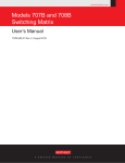
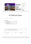
EEPROM App
Application
EEPROM
Master
EEPROM
Slave
IIC
IIC Driver
IIC HAL
HAL MM
HAL UART
MM Hardware
UART Hardware
Figure 1 – Overview of SW Design structure.
4
Chapter 3.Development Environment
The Sample code is provided as a project generator with the RSK. To create the sample code project follow the instructions in the RSK
Quick Start Guide.
3.1.Serial port usage
The application gives user instructions via the serial port. It is also possible to configure the sample code to display debug messages,
see 3.1.1Serial Debug Messages.
To view the serial output the following settings are required on a suitable terminal program:
Baud: 57600. Data: 8 Bit. Parity: None. Stop Bits: 1. Flow: None.
3.1.1.Serial Debug Messages
When developing software it is useful to be able to get debug information out at runtime without stopping code from running such as when
stepping in a debugger. The software includes debug messages that can be utilised in a system that supports printf(). The sample
application does support printf() and the output is viewable via the serial port of the RSK.
The level of debug message can be set using the #define DEBUG_LEVEL. This is described in the file IIC_Common.h. Note that a high
level of debug messages can significantly slow down the system. Reducing the debug level reduces program ROM size as the unused
debug messages are removed by the pre-processor. Note: The DEBUG_LEVEL does not affect the level of instructions output by the
application code. A Release build of the code (‘Release’ is defined) removes all debug message regardless of the DEBUG_LEVEL.
5
Chapter 4.IIC Driver
The IIC Driver consists of two main layers. The top layer implements the API of the IIC driver that an application would use and contains
the majority of the functionality of the driver. The bottom layer, the IIC Hardware Abstraction Layer (HAL), provides a generic API for the
top layer to access a particular channel’s hardware. This abstraction of the hardware means that the top layer can work, without change,
with any HW that supports the IIC HAL API. Because much of the functionality of the IIC driver is in the top layer it means that the HAL for
a particular channel is kept relatively light and can concentrate on the HW access. This simplifies the addition of new HW support by the
IIC driver.
6
4.1.IIC Driver API
Source Files: IIC.h and IIC.c
The following API functions all take a channel ID as a parameter so they are all IIC channel-specific.
They all return an error value as defined in the file IIC_Common.h.
Function Name
Description
IIC_Open
Opens the channel in slave mode. Configures the clock bit rate for use in master mode.
IIC_Close
Closes the channel.
IIC_Reset
To be used after an error to reset the channel. Sets the channel to slave mode slave.
Master Mode Specific
These functions will automatically switch the IIC to master mode if required and then when completed,
Functions:
or when arbitration is lost, will switch back to slave mode to allow another master to access the bus.
Note: These functions are only available if IIC_MASTER_MODE_SUPPORTED is #defined, which it is by
default. See Section 6.2 Building for Master-only or Slave-only Operation
IIC_SetCallBackDone
Register a call-back function with the driver that will be called when any of the asynchronous master
operations complete. The use of this is optional.
IIC_SetSlaveAddr
Set the slave address of the slave that you want to access. Use this before trying to read or write to
the slave. Note: This does not have to be used to set the R/W bit in the slave address byte, this will be
set automatically by the SW depending upon the operation being requested.
IIC_Write
Write data to the slave. This automatically generates a start condition, addresses the slave, sends the
data and ends with a stop condition. This starts an asynchronous operation.
IIC_WriteNoStop
The same as the IIC_Write function but a stop is not generated at the end. This is useful when
accessing EEPROMs. This starts an asynchronous operation.
IIC_Read
Read data from the slave. This automatically generates a start condition, addresses the slave, sends
the data and ends with a stop condition. This starts an asynchronous operation.
IIC_Stop
Generate a stop condition. The use of this function should not be necessary in normal operation but
has been provided as a possible way of dealing with error conditions. This starts an asynchronous
operation.
IIC_GetStatus
Get the status of the driver. This has been provided primarily so that a user can find out if an
asynchronous operation has completed.
IIC_WaitComplete
This is a blocking function that waits until an asynchronous operation has completed.
Slave Mode Specific
Note: These functions are only available if IIC_SLAVE_MODE_SUPPORTED is #defined, which it is by default.
Functions:
See Section 6.2 Building for Master-only or Slave-only Operation
IIC_SlaveConfig
Configure the IIC driver for when it is in slave mode. This primarily provides the driver with functions to
call when it receives data or when it is required to write data.
7
4.2.Hardware Abstraction Layer
The HAL is a hardware specific layer that provides a non hardware-specific API. Each channel that the IIC Driver supports must be
support the following HAL API. A function called “IIC_HAL_Get_API” provides access to this API for a specific channel by returning
an IIC_HAL_API pointer. The implementation of this API is HW-dependant. Note that this interface is not directly accessed by an
application so it is not important for an application developer to understand this if using the drivers as supplied.
4.2.1.HAL API
Source Files: IIC_HAL.h and IIC_HAL.c plus particular driver files.
Function Name
Description
Init
This will be the first function called. Used to register call-backs for this HAL layer to call the main IIC
Driver layer. See section Call-backs after this table.
Open
Open the channel ready to operate but don’t enable interrupts.
Close
Close the channel and disable interrupts.
Reset
Reset the module so it should be operational in slave mode.
SetMode
Set the specified mode. Note however that this will not be used to switch between master and slave
modes it will only be used to switch between read and write modes.
InterruptEnable
Enable any necessary interrupts.
InterruptDisable
Disable all interrupts.
SetStart
Generate a start condition on the bus.
SetStop
Generate a stop condition on the bus.
Write
Transmit a specified byte of data. (Use the current mode – master or slave)
StartReadACK
Start a process of reading a byte of data and then generating an ACK.
StartReadNACK
Start a process of reading a byte of data and then generating a NACK.
Read
Read a byte of data that has already been received.
ClearReadBuffer
Clear any data in the read buffer.
SetSlaveAddress
Specifies a slave address for the channel when it is in slave mode.
8
4.2.2.Call-backs from HAL
The main IIC driver layer communicates with the HAL using the HAL API. However, for interrupt driven actions the HAL needs to be able
to call the main layer. This is done by the main layer registering call back functions using the HAL API’s ‘Init’ function. The following
call-backs are registered:
Function Name
Master Mode
Start
In Master Mode: Call after generating a start condition at the point that the slave address can be
written out by main layer.
In Slave Mode: Call after getting a start condition followed by an address match with the slave address
assigned to the driver.
Stop
Call after generating/detecting a stop.
ACK
Call after detecting an ACK.
NACK
Call after detecting a NACK.
Error
Call if an error is detected during interrupt handling.
4.3.Specific HW drivers
4.3.1.Multi-Master IIC Bus Interface
Source Files: IIC_HAL_MM.h and IIC_HAL_MM_M16C6C.c
This fully implements the HAL API for both master and slave operation for the Multi-master IIC Bus Interface of the M16C/6C.
4.3.2.Serial Interface UART 2 – IIC Mode
Source Files: IIC_HAL_UART.h and IIC_HAL_UART_M16C6C.c
This fully implements the HAL API for both master and slave operation for the M16C/6C UART2 in IIC mode.
9
4.4.ROM Size
The following table gives a guideline of the required ROM used by a release build of the driver. This is with level 3 optimisation with option
“Speed followed by ROM size” selected.
Build with Master and Slave support.
Driver Part
Data (bytes)
Program (bytes)
Common (always required)
37
2788
UART
60
1130
MM
69
1067
Driver Part
Data (bytes)
Program (bytes)
Common (always required)
37
2124
UART
56
673
MM
65
1061
Driver Part
Data (bytes)
Program (bytes)
Common (always required)
37
975
UART
52
752
MM
52
371
Build with just Master support.
Build with just Slave support.
10
Chapter 5.Sample Application
An RSK running the sample application using the default configuration can act as a both a simulated slave EEPROM device and/or an IIC
master controlling a slave EEPROM. A single IIC channel is used, this can be chosen from the two channels that the M16C/6C supports,
the “Multi Master IIC Bus Interface” (MM) or the UART2 (UART). The application does not need to be re-built to change configuration as
it can all be controlled by the switches on the RSK at runtime.
The easiest way to see the sample working fully in a multi master environment is to connect two RSKs together via IIC. In this way both
RSKs will be able to run as both a slave and a master. Alternatively if only master mode is required then an RSK can be connected to a
real IIC EEPROM.
5.1.EEPROM Support
The EEPROM must support the addressing (device and memory) as specified below. This is what the Renesas 16K EEPROM
(R1EX24016ASAS0A) uses and is what this sample has been tested with.
Start
Device Address Byte
Memory Address Byte
Slave Address (Fixed)
1
0
1
Memory Address (11 Bits)
0
A10
A9
A8
A7
A6
A5
A4
A3
A2
A1
A0
R/W
5.2.RSK IIC Pins
The MCU uses the same pins for IIC if using either the UART or the MM. The RSK brings these pins out to a header.
IIC Signal Name
MCU Pin Number
Header
SCL
27
JA1_26
SDA
28
JA1_25
Ground
12 and 62
JA1_2
These three pins must be connected to the corresponding pins on the other IIC device (other RSK).
5.3.Source Files
IIC_EEPROM_App.h, IIC_EEPROM_App.c
Main application loop
IIC_EEPROM.h, IIC_EEPROM.c
Functions using IIC Master Mode to access an IIC Slave EEPROM
IIC_EEPROM_Slave.h, IIC_EEPROM_Slave.c
Simulated IIC Slave EEPROM
11
5.4.Running the sample application
The following describes the full possible operation of the application. How you actually operate it depends upon what you are connected
to.
So for example if you are connected to a real IIC EEPROM then the slave operation of the RSK (Stage 2 below) is not relevant and you
should, after selecting the required channel (Stage 1 below) leave “Slave-only mode” by pressing SW1 (Stage 3 below).
Note also that this assumes the application has been built in its default configuration and therefore has support for slave and master mode
and the UART and MM channel.
1. After a power on reset the first thing to do is select the IIC channel to use.
The top line of the LCD displays the name of a channel, initially this is the MM. SW2 loops through all available channels. In this case
this is just the UART and the MM. When the desired channel is displayed on the LCD, press SW1 to select it.
2. After selecting a channel, the RSK becomes a simulated IIC EEPROM.
The LCD shows it is in IIC Slave-Only Mode by displaying the word “Slave”. Following the word Slave, the value of the first byte of the
simulated EEPROM is displayed. At this point an IIC master can read and write to the simulated EEPROM. The value of the first byte will
be kept updated on the screen and LED0 will briefly flash when the slave is addressed by a master.
3. To leave the Slave-only mode, press SW1.
In this mode the RSK still continues to act as a slave EEPROM, however the LCD will not be updated with slave information anymore.
Only LED0 will flash to indicate slave activity.
Master operations are now enabled. The bottom line of the LCD will display the word “Master”.
For master operations to work the RSK must be connected to a slave EEPROM. This can be another RSK running this application or a
real EEPROM device.
When a master operation is started LED1 will flash briefly.
•
Press SW2 to perform a master write of data to the connected slave EEPROM. The data is written starting at address zero in
the EEPROM. The first byte is a ‘count’ value which will be incremented following every write. The rest of the data comprises
the string “Renesas IIC”. If the data is successfully written then the LCD will display the ‘count’ value written, e.g. “Wrote 01”. If
the write operation fails the LCD will display “Error W.”
•
Press SW3 to perform a master read of data. Thirteen bytes (the same number that are written in a master write operation) are
read from address zero of the connected slave EEPROM. If the data is successfully read then the LCD will display the value of
the first byte, e.g. “Read 01”. Hence if the slave EEPROM was previously written to by this application this will be the ‘count”
value previously written. This allows confirmation that what was last written is now being read back. If the read operation fails
the LCD will display “Error R.”.
•
Press SW1 to go back to Slave Only Mode. This disables SW2 and SW3 and the LCD again displays Slave information.
12
Chapter 6.Using the IIC Driver in your own Application
There are a number of ways that you can make use of the IIC sample code for your own application. For example:
1.
Taking the IIC driver and add it to your own workspace and application.
2.
Removing the sample application from the sample workspace and replacing with your own.
3.
Adapt the sample application to meet your own requirements.
4.
Use portions of the code to help develop your own code.
The modular design of the SW and the clear separation between driver and application code makes these options possible. The key point
to remember is that if you are planning on developing your own application that will use the driver as it is then the only API you have to work
with is the IIC Driver API as specified in file IIC.h. The following table summarises all the files:
Table 1: Driver source files
Layer
File
Description
IIC Driver
IIC_Common.h
Configuration options and other shared information
IIC Driver
IIC.C and IIC.h
Main
IIC Driver HAL
IIC_HAL.c and IIC_HAL.h
Hardware Abstraction Common files
IIC Driver HAL: Multi-Master
IIC_HAL_MM_M16C6C.c and
Multi-Master HW specific driver. These files are not needed if only
IIC_HAL_MM.h
using the UART.
IIC_HAL_UART_M16C6C.c and
UART HW specific driver. These files are not needed if only using
IIC_HAL_UART.h
the Multi-Master module.
IIC Driver HAL: UART
Table 2: Sample application source files
Application
IIC_EEPROM_App.c and
Main application loop
IIC_EEPROM_App.h
Application
IIC_EEPROM.c and
Functions using IIC Master Mode to access an IIC Slave EEPROM
IIC_EEPROM.h
Application
IIC_EEPROM_Slave.c and
Simulated IIC Slave EEPROM
IIC_EEPROM_Slave.c
13
6.1.Building for just UART or just MM support
The RSK sample application allows the user, at run time, to select to use either the UART or the MM channel. If you only require support
for a single channel then it is easy to remove the unwanted channel from the build to save memory.
1.
Remove the files from the project that make up the unwanted HW specific driver, see Table 1: Driver source files.
2.
Edit file IIC_Common.h so that only a single channel is defined. Note that the channel IDs must start at zero.
Two Channels
MM only
UART only
#define IIC_NUM_CHANNELS 2
#define IIC_NUM_CHANNELS 1
#define IIC_NUM_CHANNELS 1
#define IIC_CHANNEL_MM
0
#define IIC_CHANNEL_MM
#define IIC_CHANNEL_UART
#define IIC_CHANNEL_UART
1
3.
0
0
Edit function IIC_HAL_Get_API in file IIC_HAL.c to remove the code that refers to the channel you are removing.
For example, here is the function with the UART support removed leaving only the MM support.
const IIC_HAL_API* IIC_HAL_Get_API(unsigned char Channel)
{
/*MM*/
if(IIC_CHANNEL_MM == Channel)
{
return IIC_HAL_MM_Get_API();
}
return NULL;
}
4.
Remove the #include to the header file of the unwanted driver from the top of file IIC_HAL.c
6.2.Building for Master-only or Slave-only Operation
The RSK sample application demonstrates both master and slave operation. If, however, you require only master or slave operation then
the code can be configured to be built for only a single mode thus reducing memory requirements. This is achieved by editing the file
IIC_Common.h:
/*Select the IIC modes that the IIC driver will support:If a mode is required then set to 1.
If a mode is not required then set to 0, this will save ROM and RAM.*/
#define IIC_MASTER_MODE_SUPPORTED 1
#define IIC_SLAVE_MODE_SUPPORTED
1
6.3. Peripheral Function Clock
To enable the IIC driver to correctly configure itself to a requested bit rate it needs to know the value of the peripheral function clock f1.
If using a different clock configuration to the sample application then ensure that the value of the #define CLOCK_F1 in file IIC_Common.h
is set correctly. For example:
/*32MHz f1 Clock */
#define CLOCK_F1 32000000UL
14
Chapter 7.Typical Usage
This chapter shows how an application would typically use the IIC driver. In addition to the information presented here it is recommended
that the sample application is studied including running and stepping through it using the debugger if possible.
All API functions take a channel ID as a parameter. This ID can be found in file IIC_Common.h. In the code snippet below from
IIC_Common.h there are two IDs defined:
/* Define a channel ID for each supported channel starting at 0 then consecutive.*/
#define IIC_CHANNEL_MM
0
#define IIC_CHANNEL_UART 1
7.1.Master Mode
1.
Before a channel can be used it must be opened using the IIC_Open function. This function takes as a parameter the clock bit
rate (Hz) that the driver should use. The datasheet of the IIC device you are planning to connect to will specify a range, or at
least a maximum value, that it supports. The values that are supported by the IIC driver depend upon the particular channel
(MM or UART) being used and the peripheral clock value (f1):
Table 3: Bitrates if f1 = 32MHz
Channel
Clock Min
Clock Max
UART
32 kHz
16 MHz
MM
9 KHz
666 KHz
The IIC_Open function will return error code IIC_ERR_BAUD if the value supplied can not be generated.
Example usage:
error = IIC_Open(IIC_CHANNEL_MM, 100000);
2.
Use the function IIC_SetSlaveAddr to specify the address of the IIC slave device that you wish to communicate to next. This
setting will be stored and used in subsequent master operations and so this function only needs to be called again when you wish
to address a different slave device. Note that the parameter SlaveAddr must hold the 7 bit slave address in bits 1 to 7. Bit 0, the
R/W bit of the slave address byte, can be set as any value as it will be automatically be set by the driver depending upon the
operation being performed.
Example usage:
error = IIC_ SetSlaveAddr (IIC_CHANNEL_MM, 0xA0);
3.
At this point the driver is ready to perform a master read or write operation.
Master Write
The function IIC_Write performs a complete master write operation:•
Generates a start condition on the bus.
•
Transmits 7-bit slave address followed by R/W bit set low. Expects ACK from slave.
•
Transmits the data supplied to the function. An ACK from the slave is expected after each byte.
15
•
Generates a stop condition on the bus.
NOTE: Functions IIC_WriteNoStop and IIC_WriteNoStart are provided in cases where the stop and start
conditions need to be controlled differently to above. This is often used when using a combined message
format to access an EEPROM.
Master Read
The function IIC_Read performs a complete master read operation:-
4.
•
Generates a start condition on the bus.
•
Transmits 7-bit slave address followed by R/W bit set high. Expects ACK from slave.
•
Reads a specified number of bytes from the slave device, ACK’ing each one except the last.
•
Generates a stop condition on the bus.
Wait for the asynchronous master operation (Write or Read) to finish.
If an asynchronous master operation function, such as IIC_Read or IIC Write, returns IIC_ERR_OK it means the
operation will be started. The driver provides several methods an application can use to know when the operation
has completed:
•
Wait for the operation to complete by calling the blocking function IIC_WaitComplete. This will only
return when the operation has completed.
•
Poll the driver using IIC_GetStatus until the status returned is not IIC_ERR_BUSY.
•
Setup a call back function, that the driver will call when the operation completes, using the function
IIC_SetCallBackDone.
After an operation has completed another one can be started.
7.2.Slave Mode
Before a channel can be used it must be opened using the IIC_Open function. If opening a channel only for slave mode the value of
the BitRate parameter is not used and can be zero.
Use the IIC_SlaveConfig function to hook your slave handling functions into the IIC driver. You need to supply functions that the
driver will call when:
1.
A start condition is detected. (cbStart).
2.
A stop condition is detected. (cbDone)
3.
The slave driver has read a byte of data (cbRead). This function provides the application with the data the master is sending
during a master write operation a byte at a time.
4.
The slave driver must write a byte of data (cbWrite). This is how the application provides the driver with data to send to the
master in response to a master read request.
16
Chapter 8.Additional Information
For details on how to use High-performance Embedded Workshop (HEW), refer to the HEW manual available on the CD or installed in the
Manual Navigator.
For information about the M16C/6C series microcontrollers refer to the M16C/6C Group Hardware Manual.
For information about the M16C/6C assembly language, refer to the M16C Software Manual.
For information about the E8A Emulator, please refer to the E8A-USB Emulator User’s Manual
Further information available for this product can be found on the Renesas website at:
http://www.renesas.com/renesas_starter_kits
General information on Renesas Microcontrollers can be found on the following website.
Global: http://www.renesas.com/
17
Renesas Starter Kit for M16C/6C
IIC Sample Code User's Manual
Publication Date Rev.1.00 09.July.2009
Published by:
Renesas Technology Europe Ltd.
Dukes Meadow, Millboard Road, Bourne End Buckinghamshire
SL8 5FH, United Kingdom
©2009 Renesas Technology Europe and Renesas Solutions Corp., All Rights Reserved.
Renesas Starter Kit for M16C6C
IIC Sample Code User’s Manual
1753, Shimonumabe, Nakahara-ku, Kawasaki-shi, Kanagawa 211-8668 Japan
REG10J0163-0100