1
US006731992B1
(12) United States Patent
(10) Patent N0.:
(45) Date of Patent:
Ziegler, Jr.
(54) REMOTELY ACCESSIBLE ENERGY
Designer Manual Version 4.0, Sep. 1998, Atlantic Software,
Eldon W. Ziegler, J r., Clarksville, MD
(Us)
(73) Assignee: Atlantic Software, Inc., Clarksville,
MD (US)
(*)
Notice:
May 4, 2004
2000 ProAtion for Windows 95 and NT—User Manual/
CONTROL SYSTEM
(75) Inventor:
US 6,731,992 B1
Subject to any disclaimer, the term of this
patent is extended or adjusted under 35
U.S.C. 154(b) by 521 days.
Inc.
ES—1400e—Enerlogic System 1400e User’s Manual,
1987—1991, Enerlogic Systems, Inc., Table of Contents
w/pages 3—2,3—3, and B—6 through B—9.
* cited by examiner
(21) Appl. No.: 09/718,227
Primary Examiner—Ramesh Patel
(74) Attorney, Agent, or Firm—Crowell & Moring LLP
(22) Filed:
(57)
Nov. 22, 2000
ABSTRACT
(51)
Int. Cl.7 .............................................. .. G05B 19/18
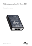
An advanced remotely accessible energy control system
(52)
US. Cl. ............................. .. 700/65; 700/9; 700/19;
utilizes a client/server software architecture, and an “open”
communication protocol, such as the well known TCP/IP
700/20; 700/66; 700/17; 700/83; 702/188
(58)
Field of Search .......................... .. 700/9, 3, 65, 66,
700/17, 19, 20, 83; 702/188
(56)
puters incorporating operating systems which are well suited
References Cited
U.S. PATENT DOCUMENTS
5,805,442 A
*
5,845,230 A
* 12/1998 Lamberson
5,909,368 A
5,923,557 A
*
*
6/1999
7/1999
Nixon et a1.
Eidson .............. ..
.... .. 700/2
700/129
5,956,487 A
5,960,214 A
*
*
9/1999 Venkatraman et a1.
9/1999 Sharpe et a1. ..
.. 709/218
700/9
5,975,737 A
* 11/1999
5,980,090 A
6,038,486 A
* 11/1999 Royal et a1.
* 3/2000 Saitoh et a1. ..
6,092,078 A
*
6,176,421 B1 *
9/1998 Crater et a1. ................. .. 700/9
. 702/56
Crater et a1.
.... .. 700/9
.. 700/241
700/96
7/2000 Adolfsson ................. .. 707/102
1/2001
protocol for design-in remote accessibility. Multiple graphic
user interface clients can operate on widely available com
Royal et a1. .............. .. 700/241
OTHER PUBLICATIONS
ProAtion Energy Control System Sample Office System, no
to graphic user interface functions, while the energy control
server and the input/output interface components can oper
ate on a separate computer, using other or different operating
systems, which are adapted to the processing performed
there. According to the invention, the graphic user interface
software is resident on one or more graphic user interface
consoles or clients, so that processing for formatting data for
display, and processing of input actions taken by a system
user are of?oaded from the server to the graphic user
interface clients. Data describing the format of the display is
stored on the server, so a user can move the graphic user
interface software to another computer, connect to the server
and view the system information, without transporting ?les
describing the format of the display.
date.
ProAtion 2000 Energy Control System.
35 Claims, 18 Drawing Sheets
@
TCP/IF SERVER
PROCESS FOR u.|.
CONNECTIONS
%
OPEN SERVER
CREATE TCP/lP
SERVER PROCESS
FOR u.|.
WAll' FOR
couuzcmus
counccnou
mou u.|.
'
0N
PROCESS T0 I/O *11]
CREATE
PROCESS FOR
SERVER
common
1
mm u.:.
START ONE
sacouu
mm
“
$3
Wm FOR
MESSAGE
I
CREATE
pnocsss FOR
E
éaglc'g
MESSAGE TO
wAn FOR
WAIT FOR
“HER
saw ‘10 ul
Freon; u.|.
25am
SEND
Tap/n,
I
1
MESSAGE
I
MESSAGE
U.S. Patent
May 4, 2004
Sheet 1 of 18
US 6,731,992 B1
CONTROLLED w 2
DEDICATED DR DIAL-UP
COMMUNICATIONS LINE
DEV'CES
PROPRIETARY PROTOCOL
SENSORS N3
I0
DEDICATED ENERGY
DEDICATED OR DIAL-UP
CONTROL SYSTEM
CONTROLLED M2
COMMUNICATIONS LINE
INCLUDING MEMORY
DEVICES
* RESIDENT DATABASE,
PROPRIETARY PROTOCOL CONTROL LOGIC AND
SENSORS M3
INTERFACE TO
DEVICES
PRIOR 'ART
INTERNET, LOCAL
AREA NETWORK
(LAN) 0R
DWFUP
rep/II:
4
ONE OR MORE GRAPHIC
USER INTERFACE
CONSOLES (CUENTS)
7
\
8
2
1
/
/ SERVER /
CONTROLLED
DEvIcE I/O
g
DEVICES
CONIRoLLER L INTERFACE(S)
sENsORs
\5
I/O DEVICE INTERFACE SOFTWARE
INTEGRATED WITH CONTROLLER OR
I
3
A SEPARATE PROCESS WITHIN SERVER
FIG]:
U.S. Patent
May 4, 2004
101
Sheet 3 of 18
132
US 6,731,992 B1
133
NETWORK
TELEPHONE
oevuc'e
INTERFACE
INTERFACE
INTERFACE
OS DRIVER
OS DRIVER
OS DRM-IR
\
I04AI
LINUX
03
\/
T8054?
m6
1104B
104C
FILE
SERIAL
SYSTEM‘
comm. ‘
107
DATABASE
ON FLASH
1 5
'
KIOB
A
MEMORY
lGDiSK!‘
IOQI
CONTROLLER
APPUCATION
SOFTWARE
DEVICE INTERFACE
APPLICATION
SOFTWARE
110
I11
FIG.6
U.S. Patent
May 4, 2004
Sheet 4 of 18
US 6,731,992 B1
ps onsol - ProActin ECT
?le Edit \[xew Ijelp
Outside
86
Temperature
Gymnasium
Class Rooms
76
72
7O
66
73
65
75
72
75
Outsxde
Lights
-—
—-
—
—
—
Suite
N.W.
Outside
R0 m
Room
100A
Comer
Kitchen
314
315
73
69
73
72
66
72
Book
By G4
_
73
65
75
By G1
Ready
Store
R m
Room
//,
H607
U.S. Patent
May 4, 2004
Sheet 5 of 18
US 6,731,992 B1
Ups Console - ProAc?TJJ-ECL
file Edit \?ew Ijelp
General Housekeeping
General
9;00:09 0m
?oor (310161020103610461056106610761086109611061116112
0"
52:, G201(32026203620462056206620762086209621002116212
011
Figgr G301630263036304030563066307030863096310631 16312
F?gr G4016402C4038404640564060407640864096410641 16412
1/0
£2, 050105020503650405050506650705080509651065116512 PL0®
F232! G601G6026603660466050606660766086609861006116612
8th
Floor G801(580268036804680568066807680868096810681 10812
9th
Floor G901690269036904090509066907090869096910691 16912
Ready '
é
F1608
U.S. Patent
May 4, 2004
Sheet 6 of 18
US 6,731,992 B1
Book Store
Se?ings Heat Scheduie Cool Schedule
Fun Schedule
Heat
Cool
~Mode
~Schedu|e Mode
Set Point
Set Point
O Off
@ Scheduled
8g _ —
_
80 _ P_
O Heat
O 0001
0 Comfort
0 Economy
_
_
(0) Auto
0 Unoccupied
{:1
-
-
:1
-
‘
-
'
~
40 - 4
65
[1 User Hold
~F0n
@ M0
—Use Which Schedde?-——
@ Use Individual Schedule
O 0"
0 Use Master Schedule
40 " -
F
80
a
F
RG09
U.S. Patent
(
START
May 4, 2004
)
LOAD
Sheet 7 of 18
US 6,731,992 B1
TCP/IP sERvER
PROCESS FOR u.|.
ooNNEcnoNs
DATABASE
I
CREATE TCP/IP
OPEN sERvER
f
SERVER PROCESS
FOR 0.1.
WAIT FOR
coNNEcnoNs
coNNEcnoN
|
FROM UJ.
CREATE TCP/lP
I
coNNEcuoN
CREATE
PROCESS TO I/O
PROCESS FOR
SERVER
CONNECHON
1
FROM u.|.
START ONE-
]
SECOND
RNER
_.__..
I
CREATE
WAIT FOR
PROCESS FOR
nNER 0R
FRO“ U‘
NEssAeE
MESSAGES
k
"
Egg
WAIT FOR
MESSAGE TO
WAR FOR
“HER
SEND T0 N1.
FROM u.:.
§EN0
SEND
'FPMESSAGE
ROCESS
MESSAGE
TO
u| VIA
MESSAGE
TO
A v1A IPC
NEssAcE
TCP/IP
'
__I
FIG.1OA
MESSAGE
U.S. Patent
May 4, 2004
Sheet 8 0f 18
US 6,731,992 B1
TCP/IP SERVER PROCESS FOR UJ. CONNECTIGNS
oPEN
SERVER
—_...{
wArr FOR
coNNEcnDN
FROM u.|.
WATT FOR
——
MESSAGE
I
SEND
CREATE
PROCESS FOR
GoNNEcnoN
MADE
coNNEGnoN
MESSAGE TO
FROM w.
A VIA IPC
__|
‘
CREATE
PROCESS FDR
MESSAGES
FROM UJ.
—
SEND TO u.|.
'
MESSAGE?
ND
SEND
“wag/‘T0
TCP/lP
___.._|
YES
SEND
TERMINATE
MESSAGE TO
CVTAIPC
PROCESS
MESSAGE TO
YES
cDNNEcmN
TERMINATE
c
WAN FOR
TERMINATE
FROM U.l.
SEND
coNNEcnoN
LOST
MESSAGE TO
A VIA IPC
I
TERMINATE
PRocEss
U.S. Patent
May 4, 2004
Sheet 9 of 18
US 6,731,992 B1
8
TCP/IP
CONNECTIDN
PRGGESS TO I/()
SERVER
CONNECT VIA
TCP/IP T0 1/0
SERVER
FAILED
CREATE
PROCESS FOR
MESSAGES
FRGM 1/0
DELAY FOR 30
MAR FOR
MESSAGE TO
MAR FOR
MESSAGE
SECONDS
SEND TO l/O
FRoM 1/0
SERVER
SERVER
SEND
MESSAGE TO
|/o s
\M
SEND
MESSAGE TO
A VIA IPC
TCP/IP
,___i
FHGQWC
U.S. Patent
May 4, 2004
Sheet 10 0f 18
ITMER PROCESSING
PROCESS
I
TTMER
II
CHECK DME-DF-
DISPLAY THE TIME
OF DAY ON
THE LCD
DAY SCHEDULES
FOR ANY CHANGES
NOW DUE
UPDATE
lN-MEMORY
DATABASE WITH
NEW SETTTNG
CHECK UST 0F
HOUDAYS, SET
HOUDAY FLAG
FOR SCHEDULES
AND NOTIFY ANY
U1. CONNECTIONS
SEND NEW
SETTING TD
ANY U.I.
CDNNECTTDNS
VIA IPC
MESSAGE TO C
SEND NEW’
CHECK MASTER
SCHEDULES T0
SETTING TO I/D
DErERMmE
SERVER VTA IPC
MESSAGE TO D
WHICH IS ACTIVE
ON THIS DATE.
IS THE ITME
A DIFFERENT
MINUTE?
RETURN
YES
RETURN
US 6,731,992 B1
U.S. Patent
May 4, 2004
Sheet 11 0f 18
US 6,731,992 B1
MESSAGE PROCESSING
DEIERMINE
MESSAGE
SOURCE
MESSAGE
CONNECTION
common
MESSAGE
FROM m.
MADE
LOST
FROM |/o
MESSAGE
MESSAGE
PROCESS
MESSAGE
FROM U '
4-:
ADD
CONNECTION
TO LIST 01-‘
ACTIVE
couuecnons
1
REMOVE
connecnou
FROM LIST OF
ACTIVE
conuecnons
1
RETURN
RETURN
PROCESS
MESSAGE
FROM l 0
/
U.S. Patent
May 4, 2004
Sheet 12 of 18
PROCESS MESSAGE FROM I/O
UPDATE
VALUES IN
DATABASE
NOTIFY ANY U.|.
CONNEC'HONS
VIA IPC MESSAGES
T0 C
COMPUTE
ANY SEI'HNGS
TO BE
Cl-LANGED
SEND COMMANDS
T0 l/O SERVER
VIA IPC MESSAGES
T0 0
NOW-Y ANY
UJ. CONNEC'HONS
VIA IPC MESSAGES
T0 C
l
RETURN
FIG.1OF
US 6,731,992 B1
U.S. Patent
May 4, 2004
Sheet 13 of 18
US 6,731,992 B1
PROCESS MESSAGES FROM U.l.
DETERMTNE
MESSAGE
TYPE
REQUEST FOR
CHANGE
INFDRMADDN
SEITTNGS
MESSAGE
MESSAGE
RETRIEVE INFORMATION
FROM TN-MEMORY
DATABASE
Mom ANY OTHER
u.|. GDNNEGTTDNS 0F
GRANGES vlA IPC
MESSAGES T0 0
NOHFY uM. \AA
'
IPC MESSAGES
T0 T3
I
UPDATE
VALUES IN
DATABASE
REIURN
SEND GDMMANDS
T0 l/D SERVER
VIA IPC MESSAGES
T0 0
1
RETURN
FIG.10G
U.S. Patent
May 4, 2004
Sheet 14 of 18
US 6,731,992 B1
@
mmAuzE
GREATE PROCESS
FOR DEVICE
B
coMMumcAnou
S
A
WAIT FGR
MESSAGE
GEIERMIME
MESSAGE
SOURCE
DEVICE
coMM.
PROCESS
M?SSAGE
FROM
COMROLLER
MESSAGE
To
CONWLLER
coMMEcnoM
MADE
MESSAGE
coMMEcnoM
LOST
MESSAGE
CREATE
TCP/IP
SEND
MESSAGE TO
SEND
MESSAGE TO
C0N" 0N
MADE
cONNWERK
CUON
SERVER
DEVICE
CONTROLLER
PROCESS
coMM.
vlA IPC
READY
FOR
PRocESs VIA
comRouER IPC MESSAGE
coMMEcnoMS
TO G
MESSAGE TO
0
M
A
A
FIG.11A
LOST
,
A
A
U.S. Patent
May 4, 2004
Sheet 15 of 18
B
US 6,731,992 B1
* ~
!
WAIT FOR IIIIER
0" MESSAGE
SEND oEvIcE
com. PROCESS
READY MESSAGE TO
A W\ IPc
IF IIIIER
PROCESS
INfHAUZE POLLING,
RESEND. DEVICE
E
WER
OPERATION AND
VERIFY TIMERS
IF MESSAGE
PROCESS
OPEN SERIAI.
HES?“
PORT DEvIcIE
CREATE PROCESS
FOR DEVICE INPUT
7
=
IIIAII FOR
DEVICE
INPUT
SEND DEVICE INPUT
MESSAGE T0
0 WI IPc
FIG.11B
c
U.S. Patent
May 4, 2004
US 6,731,992 B1
Sheet 16 0f 18
TCP/IP SERVER PROCESS FOR CONTROLLER CONNECTION
l
WATT FOR
OPEN
SERVER
MESSAGE
FROM UJ.
-———-4
WAIT FOR
CONNECTION
FROM
CONTROLLER
CONNECTION
YES
sens
TERMINATE
CREATE
PROCESS FOR
SEND
MESSAGE TO
MESSAGES
FROM
___J
WAIT FOR
MESSAGE TO
SEND TO
CONTROLLER
TERMINATE
MESSAGE?
SEND
MESSAGE TO
UJ. vm
0 VIA iPC
A VIA IPC
CONTROLLER
NO
SEND
MESSAGE TO
CONNECTION
LOST
MESSAGE TO
A VIA IPC
TCP/IP
FIG.11C
TERMINATE
PROCESS
U.S. Patent
May 4, 2004
Sheet 17 of 18
US 6,731,992 B1
PROCESS IIVIER
DETERMINE
TIRER
TYPE
POLLING
IIMER
RESEND
IIVER
DEVICE
OPERATION
VERIFY
TIMER
IIIIER
I
nun NEXT
HND NExI
DEVICE T0
DEVICE T0
‘goals?
8E POLLED
BE REIRIED
OPERAHON
QUEUE NEXT
oEVIcE
oPERAIIoN
u
IRESEND THE LAST -
COMMAND TO THE
nEVIcE
T0 POLL
THE DEVICE
sEI IVAIIIIII;
REIIIRR
VERIFIcAIIoR Ems;
HOLD THE DEVICE
oPERAIIoNs ouEuE;
START THE VERIFY
TIMER
REIURN
FIG.11D
U.S. Patent
May 4, 2004
Sheet 18 0f 18
DEVICE OPERATION!
VERIFY TIMER
DO THE
DO VERIFY
DEVICE
“HER
US 6,731,992 B1
OPERATION
MARK OPERATION
SET UP DEVICE
Ag FAILED
MESSAGE FOR THIS
DEVICE AND COMMAND
SEND ERROR TO
CONTROLLER MESSAGE
SET UP EXPECTED
To A VIA |Pc
RESPONSE FOR THIS
DEVICE AND COMMAND
SEND THE COMMAND
TO THE DEVICE
INCREMENT
ERROR COUNT
ERROR
SET WAITING
VERIFICATION FLAG;
HOLD THE DEVICE
OPERATIONS QUEUE;
START THE
VERIFY TIMER
RETURN
COUNT < 3
7
OUEUE NEXT DEVICE
OPERATION TO SEND
SEND DEVICE
FAILURE ERROR
THE CURRENT
TO CONTROLLER
OPERATION TO THE
MESSAGE
DEVICE
TO A VIA IPC
RETURN
RETURN
FIG.IIE
US 6,731,992 B1
1
2
REMOTELY ACCESSIBLE ENERGY
CONTROL SYSTEM
processor or a PC as a system control unit. Remote acces
sibility is then provided only via a proprietary softWare
protocol, or by a sloW generic PC communications products,
Which are commercially available for linking PC’s via the
Internet. One communication package Which is available for
this purpose, for example, is knoWn as pcAnyWhereTM. FIG.
BACKGROUND AND SUMMARY OF THE
INVENTION
The present invention is directed to a method and appa
ratus for remote control of electrical or electrically actuated
1, for example, illustrates this type of control system, using
systems, such as for example heating, ventilation and air
controller 1 controls a plurality of controlled devices 2 using
information supplied by the control devices, as Well as by a
suite of sensors 3, Which provide information concerning
local ambient conditions at each of the control devices. The
a PC for the central control unit. In this embodiment, a PC
conditioning (HVAC) systems, lighting systems, security
systems, laWn sprinkler systems and the like.
Computerized automation systems can improve control
PC controller in this case provides an “all-in-one” system,
over HVAC systems, and When combined With communi
cating thermostats, can result in reduced cost, as Well as
enhanced operational convenience and comfort. Communi
15
cating digital thermostats provide the reliability of conven
user interface. As noted previously, remote access to the
tional thermostats, plus the ability to communicate With an
automation system. While such digital thermostats control
heating and air conditioning on their oWn, they can also
system controller PC can be obtained only by a proprietary
protocol or a dedicated or dial-up communications line.
FIG. 2 shoWs a second embodiment of an energy control
accept temperature set point changes from the computer
system according to the prior art, Which is similar to the
embodiment shoWn in FIG. 1, except that in place of a PC,
controller and can send the current temperature and heating
and air conditioning operating conditions to the computer
controller, for the purpose of implementing a control regime.
Because communicating thermostats install in place of
conventional thermostats, they may be used With different
brands of HVAC systems. The relays in these thermostats
a dedicated processor 1a is used.
Each of the foregoing prior art systems suffers from a
25
unreliable. As a practical matter, such systems can be very
inconvenient in use. In addition, the prior art systems
thermostats, including special features, but With the added
for example:
described above do not provide a built-in security system
Which constrains actions that may be taken by a user Who
has logged into the system via the remotely situated PC. And
?nally, the controller itself must be either a PC or an
35
Multiple temperature changes throughout the course of a
equivalent dedicated processor, Which is capable of perform
ing all of the functions previously described, including
processing for graphic user interface display and processing
of input actions taken by a system user; this in turn neces
day, With separate schedules, for example, for days of
sitates the use of equipment having suf?cient computing and
memory capacity to accommodate such tasks. Accordingly,
such systems are costly.
One object of the present invention is to provide an energy
control system Which is easily and conveniently accessible
the Week and holidays.
Separate temperature schedules for each of the thermo
stats included in the HVAC system
Preheating and precooling of environmentally controlled
spaces during periods of loW energy cost, depending on
the outside temperature and the actual local interior
temperature
number of common de?ciencies. In particular, and most
importantly, communications betWeen a remotely situated
PC and the system control PC is extremely sloW and
replace the contacts inside a conventional thermostat. The
HVAC system operates as it Would With conventional
control of the computer system. SoftWare in the computer
controller uses information from the thermostats, along With
time of day schedules, outside Weather conditions and
interior conditions to improve management of the HVAC
systems. Such energy control systems therefore can include,
Which includes not only a system control database, moni
toring and control logic and an interface to the control
devices 2, but also the hardWare and softWare for graphic
from a remote location.
45
Another objection of the present invention is to provide an
energy control system in Which the functionality of the
Computer enforced limits on the amount by Which a
central control processor is limited, so that loW cost com
temperature can be changed, and for hoW long; and
Tie-in betWeen the security system and the energy control
puter equipment can be used, Without requiring a monitor,
keyboard and mouse.
system.
Still another object of the present invention is to provide
In automated, centrally controlled systems such as
a control system in Which graphic user interface function
ality is performed outside the central control unit itself, so
that different operating systems may be used for monitoring
described above, the status of all thermostats can be moni
tored centrally from a computer controller. Typically, icon
displays shoW the current temperature, as Well as heating
and cooling set points for each thermostat included Within
the system, together With its operating mode (off, heat, cool,
55
and control processing on the one hand, and for graphic
display processing on the other hand.
Yet another object of the invention is to provide such a
auto) and other information. Each of the respective thermo
control system, Which can operate on an embedded
stats is then separately controllable from the central location.
An important feature of systems such as described above
processor, Without requiring moving storage devices, such
as hard drives, ?oppy or “Zip” disk drives, or CD-ROM
drives.
is that, With appropriate communications capacity, the
Still another object of the present invention is to provide
a remotely accessible energy control system in Which input/
output interfaces betWeen the control processor and the
control devices operate on multiple, small, loW-cost
HVAC system can be monitored, and settings changed, over
an internal netWork, via the Internet, or by dialing into the
energy controller. Such remote operation can improve
service, and save trips to the operating site. Remote access
is typically secured by the use of special softWare, codes and
passWords.
KnoWn energy control systems of the type described
above have been implemented using either a dedicated
65
processors, separate from a control logic and user interface
softWare.
These and other objects and advantages are achieved by
the energy control system according to the present invention,