1
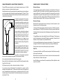
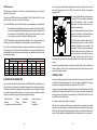
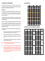
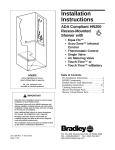
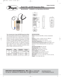
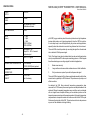
SPECIFICATIONS
MODEL 2262 pH/ORP TRANSMITTER - USER MANUAL
Revision Date 20041201
POWER
SUPPLY
9-36V DC
OUTPUT
SIGNAL
4-20mA
INPUT
Any standard pH or ORP
combination electrode
INPUT IMPEDANCE
>30GS
RANGE
(options)
0 ~ 14pH
2 ~ 12pH
4 ~ 10pH
-1000~+1000mV
-2000~+2000mV
ADJUSTMENT
Standardize ± 1pH
Slope 50% - 105% of nominal
electrode output
The model 2262 solves this problem by converting the signal from the electrode
into a standard 4~20mA process signal.
ACCURACY
<±0.2% F.S. typical
The 4~20mA signal is an industry standard which can be used with simple alarm
circuitry or sophisticated PLC and computer monitoring systems. 4~20mA signals
have three advantages over voltage signals for industrial applications.
TEMPERATURE COMPENSATOR
Pt100 Standard
Pt1000, Ni3000 (Balco) optional
1.
Better noise immunity.
OPERATING
TEMPERATURE
-5 to +65°C
2.
Longer cable runs because cable resistance does not affect calibration.
3.
Only two wires are required to provide both power and signal.
AMBIENT
HUMIDITY
0 to 90% RH
Non Condensing
pH & ORP (oxygen reduction potential or redox) electrodes are high impedance
devices which produce a mV signal proportional to the pH or ORP of a solution.
It is not always easy to use this signal directly for process control applications,
especially where the electrode is mounted a long distance from the instrument.
The model 2262 is designed to fit in a thermocouple head assembly which is then
mounted on to a pipeline pH or ORP electrode. This produces a very simple, cost
effective solution.
As standard, the 2262 offers automatic temperature compensation when
connected to a Pt100 sensor (other sensor types are available) embedded in the
electrode. Although a separate temperature sensor could be used, an electrode
with an integral sensor simplifies buffering as the electrode junction and the
temperature sensor are always at the same temperature. If automatic temperature
compensation is not required a resistor with a value near that of the Pt100 may be
fitted across the terminals of the 2262. This value does not have to be precise as
any error will be calibrated out during buffering.
-8-
-1-
CABLE PREPARATION & ELECTRODE CONNECTION
TAKING CARE OF YOUR ELECTRODE
The model 2262 uses screw terminals to connect the electrode, temperature sensor, & 4~20mA
signal so any connectors on the electrode must be removed.
Electrode Storage
Normally the electrode has a thin screened cable and the temperature sensor has two single wires
or a twin non-screened cable. Cut the cables to a length of approximately 75 - 100mm (3 - 4") from
the top of the electrode. If the electrode has a rubber sleeve around the cable this may have to be
cut back to the top of the electrode.
To prepare the screened cable start by remove
approximately 20mm (3/4") of the outer insulation.
This exposes the screen which is woven into a tube
around an inner insulator. With the help of a pointed
object separate the wires in the screen back to the
cut end of the outer insulator and twist the wires
together to form a single conductor.
The inner insulation is usually white or translucent
but it may be covered by a thin black coating. This
coating is electrically conducting and forms part of
the screen. Remove this coating as far back as
possible taking care not to damage the inner
insulation. If left, this coating could make contact
with the inner conductor shorting out the signal from
the electrode.
Now remove approximately 10mm (3/8") of the inner
insulator, exposing the inner conductor. This is
usually made up of several thin wires which should
be twisted together for strength. The inner conductor
& screen may be tinned using a soldering iron.
The insulation of the temperature compensator
wires should also be stripped back approximately 10mm and soldered if required.
Now screw the electrode tightly into the bottom of the head assembly.
Remove the lid from the head assembly and insert the model 2262 transmitter passing the cables
through the hole in the centre.
For best results always keep the pH bulb wet, preferably in pH 4.00 buffer with 1/100 parts of
saturated KCl added. Other pH buffers or tap water are acceptable storage media, but avoid
storage in distilled water. The protective boot supplied with the electrode will provide an ideal
storage chamber for long periods. Some evaporation can occur so check the liquid every couple of
months and top up if necessary. Wrapping plumber’s PTFE tape around the join between bulb and
electrode will reduce evaporation. Store in a cool place but do not allow to freeze.
Electrode Cleaning
Electrodes which are mechanically intact with no broken parts can often be restored to normal
performance by one of the following procedures:
1. Salt deposits: Dissolve the deposit by immersing the electrode in 0.1M HCl for five minutes,
followed by immersion in 0.1M NaOH for five minutes, and thoroughly rinsing with distilled water.
2. Oil/Grease Films: Wash electrode pH bulb in a little detergent and water. Rinse electrode tip with
distilled water.
3. Clogged Reference Junction: Heat a diluted KCl solution to 60-80 degrees C. Place the sensing
portion of the pH electrode into the heated KCl Solution for approximately 10 minutes. Allow the
electrode to cool while immersed in some unheated KCl Solution.
4. Protein deposits: Dissolve the deposit by immersing the electrode in a 1% pepsin solution with
a background of 0.1M HCl for five minutes, followed by thorough rinsing with distilled water.
If these steps fail to restore normal electrode response, replace the electrode.
Shelf Life
The recommended shelf life of a pH or ORP electrode is six months. Most will still work successfully
after two years if properly stored.
Buffer solutions have varied shelf lives and it is best to confirm this with the manufacturer. Most
buffers will last at least 12 months if kept sealed.
Some 10pH buffers grow a mould when left for an extended period. Often a 9pH buffer is a better
option for use in field kits.
At this stage you may wish to solder or crimp spade connectors on to the wires.
You now have four wires and three terminals. The centre terminal is a common for both the
electrode and the temperature sensor. To the terminal connect the screen from the electrode and
one of the temperature sensor wires (the sensor is not polarised so either will do), The other
electrode wire goes to the terminal marked “pH” and the other temperature sensor wire goes to the
terminal marked “Temp”.
-2-
-7-
ORP Electrodes
ORP electrodes are calibrated in a similar way to pH electrodes however only a single point
calibration in buffer is used.
If you are using an electrode without a temperature sensor then you must connect a resistor in
place of the temperature sensor. For a Pt100 this will usually be 110ohms which represents
approximately 25°C.
This value should be satisfactory for temperatures in
the range 0-50°C. There is a table shown later which
gives Pt100 resistance values for standard
temperatures. The value is not that critical as it is
trimmed out when buffering.
The most popular ORP buffer solutions are probably 86mV, 220mV, 263mV and 476mV. Try to pick
one which is close to the value you expect to be measuring.
Some of the ORP buffers require activators and need continuous agitation to get a stable reading.
1.
Rinse the electrode in distilled water and place in chosen buffer, stirring if required. When
the output has stabilised trim the Standardise adjustment to get the correct reading from
the values shown in the following table (± 10mV). (If you are using a buffer with a value
not shown below you will have to calculate the reading you require.)
For ORP transmitters the slope adjustment should be sealed. This is a factory adjustment and
should only be used when calibrating the transmitter against an accurate millivolt source.
Note. There is a conflict between European and American standards as to which polarity is used
for oxidizing and reducing. If the output of the transmitter gives a reverse polarity reading with your
instrumentation then you should reverse the electrode wires and recalibrate using the values in the
reversed polarity columns.
mV at
25°C
86
220
263
476
Range -1000 ~ +1000mV
Polarity - Normal
Polarity - Reversed
%
mA
%
mA
54.3
12.69
45.7
11.31
61.0
13.76
39.0
10.24
63.2
14.11
36.8
9.89
73.8
15.81
26.2
8.19
Range -2000 ~ +2000mV
Polarity - Normal
Polarity - Reversed
%
mA
%
mA
52.2
12.35
47.8
11.65
55.5
12.88
44.5
11.12
56.6
13.06
43.4
10.94
61.9
13.90
38.1
13.90
ELECTRODE CONTAMINATION
Various chemicals can affect the readings taken by a pH/ORP electrode by contaminating one or
other of the junctions. Sometimes the contamination is temporary and can be reversed by washing
the electrode, other times it can be permanent. Special electrodes, such as double junction types,
are available for these applications. Below is a list of some of the more problematic chemicals,
however it is advisable to consult your electrode supplier before ordering.
Sodium ions (Na+)
Proteins
Heavy Metals
Bromides
Iodides
Sulphides
Any compounds which interact with silver
-6-
Organic Compounds
Cyanides
Vegetable Oils
Once the wires are connected the excess cable can
be coiled up under the body of the transmitter before
bolting into place using the screws provided.
The 4~20mA cable is usually a twisted pair which is
inserted through the gland on the side of the head
assembly and stripped back as described for the
sensor wires. This cable may have an outer screen.
Screened cables should only be grounded at one
end, usually back at the control panel. In this case
the screen should be cut back so that it can not
accidentally short against any of the other wires or terminals. A bit of insulating tape or heat shrink
can help.
Tightening the gland should compress a rubber sleeve around the cable so that it is watertight and
cannot be pulled out. If the wire is too small some insulation tape or heat shrink may be used to
increase the diameter as required.
GROUND LOOPS
There is a possibility of ground loop problems if either side of the power supply to the model 2262
is grounded to the liquid being measured. This is often a problem with metal tanks in an outdoor
environment and especially with distributed systems such as PLC's and PC's.
A ground loop is caused by leakage currents through the solution from the pH electrode and usually
manifests itself by causing the instrument to drive hard upscale or downscale. For applications
where ground loops are possible it is recommended that a 4~20mA signal isolator such as the
model 1120 be used to break the loop.
If you suspect a ground loop problem try the following.
After checking the instrument calibration, place a sample of the process liquid in an insulated
container such as a glass beaker or a plastic bucket and place the pH electrode in this container.
Make a note of the reading. Next place the pH electrode in the process liquid tank and take another
reading. If the two readings are dramatically different, the chances are you have a ground loop.
-3-
CALIBRATING THE ELECTRODE (BUFFERING).
pH CALIBRATION TABLE.
As electrodes usually have offset and slope errors compared to the theoretical values the
transmitter needs to be calibrated to the electrode. These errors change as the electrode ages and
regular recalibration should be carried out as often as needed.
pH
pH Electrodes
For this operation you will require beakers containing distilled water, 7pH buffer solution, and 4pH
or 10pH buffer solution. The choice of 4pH or 10pH buffer solution depends on whether your
process tends towards high or low pH values. Always try to use a buffer as close as possible to your
process value for best results.
You will also need a way to measure the 4~20mA output current. You may be able to do this by
reading the display on your control instrument or by inserting a mA meter or calibrator in series with
one lead of the transmitter.
A neat trick is to fit a 1N4004 or similar silicon diode in series with the 4~20mA signal. A multimeter
set to a current range may be connected across this diode at any time to take current
measurements without disconnecting the 4~20mA loop. (Because the voltage drop across the
multimeter will be less than the 0.7V drop across the diode, when the meter is connected, no
current flows through the diode.)
The following procedure uses values for the model 2262 ranged 0-14pH. A table follows with values
for other calibrations.
1.
Rinse the electrode in distilled water and place in 7pH buffer. When the output has
stabilised trim the STD adjustment to get a reading of 12.00mA, (50%).
2.
Rinse the electrode in distilled water and place in 4pH or 10pH buffer. When the output
has stabilised trim the Slope adjustment to get a reading of 8.57mA, (28.6%) or 15.43mA,
(71.4%).
3.
No further adjustments should be required, but for peace of mind it is worth repeating the
procedure from the beginning as a check.
Note 1
The response time of this transmitter is quite slow. Make sure you wait a few seconds
until the reading is stable before making adjustments.
Note 2
When adjusting the trimmers you may notice a small change in reading after you take
your hand away from the transmitter. The signal pin is not screened and it can pick up
50/60Hz hum if you hold your hand close to it. This is more noticeable with very high
impedance electrodes such as double junction types. Once the transmitter is calibrated
and the lid fitted this is not a problem. Some people seem to generate more noise than
others - a long screwdriver can help.
-4-
0
1
2
3
4
5
6
7
8
9
10
11
12
13
Range 0-14pH
%
mA
0.00
4.00
7.14
5.14
14.29
6.29
21.43
7.43
28.57
8.57
35.71
9.71
42.86
10.86
50.00
12.00
57.14
13.14
64.29
14.29
71.43
15.43
78.57
16.57
85.71
17.71
92.86
18.86
14
100.00
Range 2-12pH
%
mA
Range 4-10pH
%
mA
0.00
10.00
20.00
30.00
40.00
50.00
60.00
70.00
80.00
90.00
100.00
0.00
16.67
33.33
50.00
66.67
83.33
100.00
4.00
5.60
7.20
8.80
10.40
12.00
13.60
15.20
16.80
18.40
20.00
4.00
6.67
9.33
12.00
14.67
17.33
20.00
20.00
RESISTANCE VALUES FOR TEMPERATURE SENSORS
Temp. °C
Pt100
0
5
10
15
20
25
30
35
40
45
50
55
60
65
70
75
80
85
90
95
100
100
102
103.9
105.8
107.8
109.7
111.7
113.6
115.5
117.5
119.4
121.3
123.2
125.2
127.1
128.9
130.9
132.8
134.7
136.6
138.5
Nearest
Standard
100
102
105
105
107
110
113
113
115
118
120
121
124
124
127
130
130
130
133
137
137
Nearest
Practical
100
110
120
130
-5-
Pt 1000
1000
1020
1039
1058
1078
1097
1117
1136
1155
1175
1194
1213
1232
1252
1271
1289
1309
1328
1347
1366
1385
Nearest
Standard
1000
1020
1050
1050
1070
1100
1130
1130
1150
1180
1200
1210
1240
1240
1270
1300
1300
1300
1330
1370
1370
Nearest
Practical
1000
1100
1200
1300