1
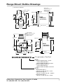
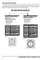
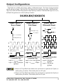
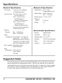
User Manual DuraCoder Incremental Output Version Encoder Products Manual: 940-0D014 940-5D013 GENERAL INFORMA TION INFORMATION Important User Information The products and application data described in this manual are useful in a wide variety of different applications. Therefore, the user and others responsible for applying these products described herein are responsible for determining the acceptability for each application. While efforts have been made to provide accurate information within this manual, AMCI assumes no responsibility for the application or the completeness of the information contained herein. UNDER NO CIRCUMSTANCES WILL ADVANCED MICRO CONTROLS, INC. BE RESPONSIBLE OR LIABLE FOR ANY DAMAGES OR LOSSES, INCLUDING INDIRECT OR CONSEQUENTIAL DAMAGES OR LOSSES, ARISING FROM THE USE OF ANY INFORMATION CONTAINED WITHIN THIS MANUAL, OR THE USE OF ANY PRODUCTS OR SERVICES REFERENCED HEREIN. Throughout this manual the following two notices are used to highlight important points. WARNINGS tell you when people may be hurt or equipment may be damaged if the procedure is not followed properly. CAUTIONS tell you when equipment may be damaged if the procedure is not followed properly. No patent liability is assumed by AMCI, with respect to use of information, circuits, equipment, or software described in this manual. The information contained within this manual is subject to change without notice. Standard Warranty ADVANCED MICRO CONTROLS, INC. warrants that all equipment manufactured by it will be free from defects, under normal use, in materials and workmanship for a period of eighteen months. Within this warranty period, AMCI shall, at its option, repair or replace, free of charge, any equipment covered by this warranty which is returned, shipping charges prepaid, within eighteen months from date of invoice, and which upon examination proves to be defective in material or workmanship and not caused by accident, misuse, neglect, alteration, improper installation or improper testing. The provisions of the “STANDARD WARRANTY” are the sole obligations of AMCI and excludes all other warranties expressed or implied. In no event shall AMCI be liable for incidental or consequential damages or for delay in performance of this warranty. Returns Policy All equipment being returned to AMCI for repair or replacement, regardless of warranty status, must have a Return Merchandise Authorization number issued by AMCI. Call (860) 585-1254 with the model and serial numbers along with a description of the problem. A “RMA” number will be issued. Equipment must be shipped to AMCI with transportation charges prepaid. Title and risk of loss or damage remains with the customer until shipment is received by AMCI. 24 Hour Technical Support 24 Hour technical support is available on this product. If you have internet access, start at our website, www.amci.com. Product documentation and FAQ’s are available on the site that answer most common questions. If you require additional technical support, call (860) 583-7271.Your call will be answered by the factory during regular business hours, Monday through Friday, 8AM - 5PM EST. During non-business hours an automated system will ask you to enter the telephone number you can be reached at. Please remember to include your area code. The system will page an engineer on call. Please have your product model number and a description of the problem ready before you call. ADVANCED MICRO CONTROLS INC. About This Manual Introduction This manual explains the installation and operation of AMCI’s Incremental DuraCoders. It is strongly recommended that you read the following instructions. If there are any unanswered questions after reading this manual, call the factory. An applications engineer will be available to assist you. AMCI and DuraCoder are registered trademarks of Advanced Micro Controls Inc. The AMCI logo is a trademark of Advanced Micro Controls Inc. Manuals at AMCI are constantly evolving entities. Your questions and comments on this manual and the information it contains are both welcomed and necessary if this manual is to be improved. Please direct all comments to: Technical Documentation, AMCI, 20 Gear Drive, Plymouth Industrial Park, Terryville CT 06786, or fax us at (860) 584-1973. Revision Record This manual, 940-0D014 superceeds 940-5D013. This revision adds cable type suggestions and improved the outline drawings. It was first released 04/04/05. Past Manual Revisions 940-5D013: Removed Motor Mount Configurations 940-5D012: Added Table of Contents. 940-0D011: Corrected error in the differential output table. 940-0D010: Added information on the T and F DuraCoders DC25N-B95M: Corrected ungated Z-pulse waveforms. DC25N-795M: Initial Release. Incremental DuraCoder Part Numbers Throughout this manual, the DuraCoder part number will be shown with specific digits highlighted. This is to help you easily determine your Incremental DuraCoders configuration. Highlighted digits are question marks ‘?’, fixed digits are shown with their actual values, and unrelated digits are ‘X’. For reference, the Incremental DuraCoder Part Number system is shown below. DC25 – B HOUSING SHAFT DIA. F = Square Flange S = 2.5" Dia. Servo Mount 1 = 0.375" Dia. 2 = 10 mm Dia. 3 = 0.250" Dia. BEARING SEAL DURACODER TYPE N = Incremental, Gated M = Incremental, Ungated Single Ended output only. T = Incremental, Gated 2-Speed Resolver F = Incremental, Gated 4-Speed Resolver OUTPUT SCALING CONNECTOR S = Side IF DURACODER TYPE = M, N E = End PRGM - Field Programmable 0002 to 1024 - Factory Set IF DURACODER TYPE = T OUTPUT CONFIGURATION A = Current Source, Single Ended, PRGM - Field Programmable 24 Vdc Max. 0004 to 2048 † - Factory Set † B = Current Sink, Single Ended, Multiples of 2 only. 24 Vdc Max. IF DURACODER TYPE = F C = Current Sink, Single Ended, PRGM - Field Programmable 0008 to 4096 ‡ - Factory Set with 2.2KΩ Pull Up Resistor. ‡ Multiples of 4 only. D = Differential Line Driver 5 Vdc Output Only. Not available with Type M. E = Current Source, Single Ended, with 2.2KΩ Pull Down Resistor. 20 Gear Drive, Plymouth Ind. Park, Terryville, CT 06786 Tel: (860) 585-1254 Fax: (860) 584-1973 3 Introduction to the Incremental DuraCoder DuraCoders are designed as direct replacements for optical encoders. Instead of being designed around a disk and optics, DuraCoders use a resolver as the shaft position sensor. Resolvers are absolute, single turn position sensors that are totally passive. Constructed in a manner similar to high percision motors, resolvers are analog devices. There are no sensitive optics and no glass or metal disks used to sense the angular position of the shaft. A resolver begins to operate when an AC signal, called the reference, is applied. The resolver couples this signal into two output windings. The amount of coupling varies sinusoidally as the DuraCoder shaft rotates. With the two output windings offset from each other by ninety degrees, one output winding returns the reference multiplied by the cosine of the shaft angle, the other winding returns the reference multiplied by the sine of the shaft angle. The DuraCoder electronics decodes these two return signals to determine the absolute position of the shaft. From there, the electronics generate the familiar quadrature pulse train of a standard incremental encoder. The DuraCoder also generates a marker pulse, or Z pulse, when the resolver passes through its electrical zero position. Industry Standard Connector There are four different incremental DuraCoder Types. Type ‘N’ DuraCoders are our standard product, offering a maximum position resolution of 4,096 counts per turn and a gated marker pulse. Type ‘M’ DuraCoders are identical to Type N, but have an ungated marker pulse. These two DuraCoders generate 1,024 quadrature cycles at 4,096 counts per turn resolution. You must use 4X decoding to retrive these 4,096 counts. The Type N and M DuraCoders use what it called a 1-Speed resolver. This means that the resolver outputs complete one sinusoidal cycle per rotation of the DuraCoder shaft. AMCI has two other types of incremental DuraCoders that contain either a 2-Speed or 4-Speed Decoder Electronics resolver. Type ‘T’ DuraCoders contain a 2-Speed resolver. The and Output Drivers outputs of a 2-Speed resolver complete two sinusoidal cycles per rotation of the input shaft. Therefore, a Type T DuraCoder generates a maximum 2,048 cycles, or 8,192 counts, per rotation. Type ‘F’ DuraCoders contain a 4-Speed resolver whose outputs complete four sinusoidal cycles per rotation NEMA 4 Enclosure of the input shaft. It generates a maximum of 4,096 cycles, or 16,384 counts, per rotation. The only drawback to the T and F DuraCoders are the number of marker pulses generated. Resolver Because the resolver passes through zero two or four times per turn, the DuraCoder generates two or four marker pulses. In many applications the marker pulse is not used. Therefore it is the users responsibility to check the specific applicaStainless Steel Shaft tion before using a Type T or F DuraCoder. DuraCoder Exploded View 4 ADVANCED MICRO CONTROLS INC Setting Programmable Cycles Per Turn If your DuraCoder has “PRGM” in the part number, (DC25X-BXXPRGMXX), the DuraCoder is shipped set for the maximum number of cycles per turn. If you need a different number of cycles per turn, use the following procedure to change the number. The procedure involves removing the back cover, setting the DIP switches, and putting the cover back on. Begin by removing these three screws to access the DIP switches. Use care when removing the cover. End connector DuraCoders have wires from the connector to the PC Board. Use the DIP switches to set the binary number equal to (Cycles per Turn)-1. Setting a switch ON sets a logic 0, setting a switch OFF sets a logic 1. The DIP switches binary number is always between 1 and 1,023. A value of zero is not allowed. Check your DuraCoder Type, (DC25X-BX?PRGMXX). If your DuraCoder Type is ‘N’ or ‘M’, you can ignore the rest of this note. If your DuraCoder is Type T: Your DuraCoder has a two speed resolver in it. You must set the DIP switches to ((Cycles per Turn/2)-1). The actual number of cycles per turn output by the DuraCoder will be an even number between 4 and 2,048. Your DuraCoder will also output two Z pulses spaced 180° apart. If your DuraCoder is Type F: Your DuraCoder has a four speed resolver in it. You must set the DIP switches to ((Cycles per Turn/4)-1). The actual number of cycles per turn output by the DuraCoder will be an even number between 8 and 4,096. Your DuraCoder will also output four Z pulses spaced 90° apart. O F F = L O G IC O N 1 If you don’t have a calculator to perform the decimal to binary conversion, use the table below to determine which switches should be OFF. Start with (Cycles per Turn) - 1 and subtract the largest possible number from the table. Turn the corresponding switch OFF. Continue subtracting the next largest possible number and turning the corresponding switch OFF until you have a remainder of zero. = L O G IC 0 O F F = L O G IC O N = L O G IC 0 1 For example, you want 742 Cycles per Turn so set the switches to equal 741. 741 - 512 = 229 229 - 128 = 101 101 - 64 = 37 37 - 32 = 5 5-4=1 1-1=0 (SW10 OFF) (SW8 OFF) (SW7 OFF) (SW6 OFF) (SW3 OFF) (SW1 OFF) SW # Weight SW # 10 9 8 7 6 512 256 128 64 32 5 4 3 2 1 Weight 16 8 4 2 1 Switches 9, 5, 4, and 2 are set ON. 20 Gear Drive, Plymouth Ind. Park, Terryville, CT 06786 Tel: (860) 585-1254 Fax: (860) 584-1973 5 DuraCoder Mounting All AMCI DuraCoders are designed to operate in the industrial environment and therefore require little attention. However, there are guidelines that should be observed to ensure long life. Limit transducer shaft loading to the following maximums: All DC25 Transducers Radial Load Axial Load 30 lbs. (133 N) 15 lbs. (66.7 N) Minimize shaft misalignment when coupling shafts. Even small misalignments produce large loading effects on front bearings. Use a flexible coupler whenever possible. The DuraCoder housing must be connected to Earth Ground. This is usually accomplished through its mounting. If not properly grounded by its mounting, run a heavy guage wire from the housing, or connector pin G, to an Earth Ground point as close as possible to the DuraCoder. Servo Mount Outline Drawings ( ) = D im e n s io n s in m illim e te r s 2 .5 0 " (6 3 .5 ) 0 .9 0 " T o ta l c le a r a n c e n e e d e d fo r m a tin g 0 .3 0 0 " (7 .6 2 ) S H A F T D IA . S E E N O T E 2 (5 8 .6 4 ) D C 2 5 0 .1 0 " (2 .5 ) 1 .5 " (3 8 .1 ) m a x . T o ta l c le a r a n c e o f 3 .5 " ( 8 9 ) n e e d e d fo r r e m o v a l o f m a tin g c o n n e c to r . (3 6 .3 ) S H A F T D IA . S E E N O T E 2 2 .3 1 " N F -2 B . .6 ) m in . d e p th . e s , 6 0 ° a p a rt 5 " (4 7 .6 2 ) B .C . D C 2 5 S e r v o M o u n t S id e C o n n e c t o r (5 8 .6 ) 6 C O N N E C T O R S E E N O T E 1 0 .3 0 0 " (7 .6 2 ) 0 .9 0 0 " (2 2 .8 6 ) 0 .8 5 0 " (2 1 .5 9 ) " X " in p a r t n u m b e r = " D o n 't C a r e " N O T E 1 If O u tp u C o n n M a te If O u tp u C o n n M a te 1 .4 3 " s q . 0 .3 0 0 " (7 .6 2 ) 2 .7 5 " (6 9 .8 ) m a x . C O N N E C T O R S E E N O T E 1 0 .1 0 " (2 .5 ) 3 .0 0 " (7 6 .2 ) m a x . # 8 - 3 2 U N F - 2 B . 0 .1 8 " ( 4 .6 ) m in d e p th . S ix p la c e s , 6 0 ° a p a r t o n a 1 .8 7 5 " ( 4 7 .6 3 ) B .C . # 8 -3 2 U 0 .1 8 " (4 S ix p la c o n 1 .8 7 9 ) D C 2 5 S - B ? X X X X X ? X 0 .9 0 0 " (2 2 .8 6 ) 0 .8 5 0 " (2 1 .5 9 ) 1 .2 5 0 " (3 1 .7 5 ) 1 .2 4 9 " (3 1 .7 2 ) x . o f r. S e r v o M o u n t E n d C o n n e c t o r 2 .3 1 " 1 .2 5 0 " (3 1 .7 5 ) 1 .2 4 9 " (3 1 .7 2 ) (2 2 .9 ) m a o f 3 .5 "(8 re m o v a l c o n n e c to 2 .5 0 " N O T E 2 If S h M If S h M If S h M a ft a x . a ft a x . a ft a x . t C e c s w t C e c s w D ia D ia D ia D ia D ia D ia o n to r ith o n to r ith fig : M A fig : M A m e . = m e . = m e . = te 0 te 9 te 0 u ra S 3 M C u ra S 3 M C r .3 r .9 r .2 tio 1 0 I P tio 1 0 I P n D ig 2 E 1 6 a rt# n D ig 2 E 1 8 a rt# D ig it = 7 4 7 ", D ig it = 9 3 m m D ig it = 4 9 7 ", it = S -1 M S it = -1 P M S A ,B ,C ,E : P . -1 6 C o n n e c to r. D : . D -1 0 C o n n e c to r. 1 : M in . D ia . = 0 .3 7 4 4 " 2 : , M in . D ia . = 9 .9 8 5 m m 3 M in . D ia . = 0 .2 4 9 2 " (6 3 .5 ) 0 .1 0 " (2 .5 ) 0 .1 0 " (2 .5 ) 2 .7 0 " (6 8 .6 ) m a x . ADVANCED MICRO CONTROLS INC Flange Mount Outline Drawings ( ) = D im e n s io n s in m illim e te r s 1 .0 3 2 " 0 .2 1 8 " (5 .5 4 ) d ia . F o u r p la c e s . (2 6 .2 1 ) ty p . 0 .2 5 0 " 0 .3 0 0 " (7 .6 2 ) ty p . a x . c e o f 3 .5 " (8 9 ) m o v a l o f c to r. D C 2 5 F la n g e M o u n t E n d C o n n e c t o r 2 .6 5 " (6 7 .3 ) 0 .9 0 0 " (2 2 .8 6 ) 0 .8 5 0 " (2 1 .5 9 ) 1 .2 5 0 " (3 1 .7 5 ) 1 .2 4 9 " (3 1 .7 2 ) ) m ra n r re n n e (6 .3 5 ) S H A F T D IA . S E E N O T E 2 1 .0 3 2 " (2 6 .2 1 ) 0 .9 0 " (2 2 .9 T o ta l c le a n e e d e d fo m a tin g c o 2 .9 5 " (7 4 .9 ) m a x . 2 .5 0 " (6 3 .5 ) d ia . C O N N E C T O R S E E N O T E 1 2 .6 5 " m a x . (6 7 .3 ) 1 .4 3 " (3 6 .3 ) m T o ta l c le a r a n n e e d e d fo r re m a tin g c o n n e 1 .4 3 " s q . a x . c e o f 3 .5 "(8 9 ) m o v a l o f c to r. 2 .7 5 " (6 9 .8 ) m a x . (3 6 .3 ) C O N N E C T O R S E E N O T E 1 0 .3 0 0 " (7 .6 2 ) 2 .6 5 " (6 7 .3 ) S H A F T D IA . S E E N O T E 2 D C 2 5 1 .2 5 0 " (3 1 .7 5 ) 1 .2 4 9 " (3 1 .7 2 ) 1 .0 3 2 " F la n g e M o u n t S id e C o n n e c t o r 2 .5 0 " (6 3 .5 ) (2 6 .2 1 ) ty p . 1 .0 3 2 " (2 6 .2 1 ) 2 .6 5 " (6 7 .3 ) ty p . 0 .2 1 8 " (5 .5 4 ) d ia . F o u r p la c e s D C 2 5 F - B ? X X X X X ? X 0 .9 0 0 " (2 2 .8 6 ) 0 .8 5 0 " (2 1 .5 9 ) .2 5 0 " (6 .3 5 ) 2 .6 5 " (6 7 .3 ) m a x . " X " in p a r t n u m b e r = " D o n 't C a r e " N O T E 1 If O u tp u C o n n M a te If O u tp u C o n n M a te N O T E 2 If S h M If S h M If S h M 20 Gear Drive, Plymouth Ind. Park, Terryville, CT 06786 Tel: (860) 585-1254 Fax: (860) 584-1973 a ft a x . a ft a x . a ft a x . t C o n e c to r s w ith t C o n e c to r s w ith D ia D ia D ia D ia D ia D ia fig : M A fig : M A m e . = m e . = m e . = te 0 te 9 te 0 u ra S 3 M C u ra S 3 M C r .3 r .9 r .2 tio 1 0 I P tio 1 0 I P D ig 7 4 7 D ig 9 3 m D ig 4 9 7 n D ig 2 E 1 6 a rt# n D ig 2 E 1 8 a rt# it = ", it = m it = ", it = S -1 M S it = -1 P M S A ,B ,C ,E : P . -1 6 C o n n e c to r. D : . D -1 0 C o n n e c to r. 1 : M in . D ia . = 0 .3 7 4 4 " 2 : , M in . D ia . = 9 .9 8 5 m m 3 M in . D ia . = 0 .2 4 9 2 " 7 Connector Pin Out Incremental DuraCoders use two different connectors. DuraCoders with differential output drivers use a different MS connector then the DuraCoders with single ended output drivers. The Output Configuration digit in the part number specifies the type of connector on the DuraCoder. DC25X-BXXXXXX?X Output Configurations A, B, C, E Single Ended Output Output Connector MS3102E16S-1P Mates with AMCI Part# MS-16 PIN NO. Differential Output Output Connector MS3102E18-1P Mates with AMCI Part# MSD-10 PIN NO. FUNCTION A B C D* E* F G Output Configuration D CH-A OUTPUT CH-B OUTPUT CH-Z OUTPUT +DC INPUT NO CONNECTION DC RETURN CASE GROUND * Pins D & E are connected internally FUNCTION A B C D* E* F G H I J CH-A OUTPUT CH-B OUTPUT CH-Z OUTPUT +DC INPUT NO CONNECTION DC RETURN CASE GROUND CH-A OUTPUT CH-B OUTPUT CH-Z OUTPUT * Pins D & E are connected internally F A G E D C A H B I G C J F E 8 B D ADVANCED MICRO CONTROLS INC Output Configurations DuraCoders are available with sourcing, sinking, or differential outputs. The Output Configuration digit specifies the type of output. The DuraCoder Type digit also has a bearing on the output. If the DuraCoder Type is (N) or (M), the DuraCoder generates a single Z pulse per rotation. If the DuraCoder Type is (T) or (F), the DuraCoder generates two or four Z pulses per rotation. D C 2 5 X - B X (? )X X X X ? X O u t p u t T y p e A , E O u t p u t T y p e B , C S o u r c e O u t p u t O u t p u t T y p e D S in k O u t p u t + V d c D if f e r e n t ia l O u t p u t + V d c A , B , Z O u tp u t 2 .2 K W ( O p tio n C o n ly ) A , B , Z O u tp u t A , B , Z O u tp u t A , B , Z O u tp u t 2 .2 K W A ( O p tio n E o n ly ) A A A B B B B Z - (N ,T ,F ) Z - (N ,T ,F ) Z Z - (M ) Z - (M ) Z C C W C C W R o t a t io n V ie w in g S h a f t ( )= D u r a C o d e r T y p e L o g i c 0 = I LL E E A A K K AA G G E E < 3 0 0 µ A L o g ic 1 = ( V d c - 2 .2 V d c ) m in . @ 5 0 m A R o t a t io n V ie w in g S h a f t ( )= D u r a C o d e r T y p e L o g ic 0 = 0 to 1 V d c @ L o g i c 1 = I LL E E AA K K A A G G E E 5 0 m A < 3 0 0 µ A C C W R o t a t io n V ie w in g S h a f t 5 V d c O u tp u t o L o g ic 0 = 0 .5 V @ 2 0 L o g ic 1 = 2 .5 V @ 2 0 n ly . d c m a x . m A d c m in . m A † Because a (T) Type DuraCoder contains a two speed resolver, it generates two Z pulses, or marker pulses, per rotation. These marker pulses are 180° apart. ‡ Because a (F) Type DuraCoder contains a four speed resolver, it generates four Z pulses, or marker pulses, per rotation. These marker pulses are 90° apart. 20 Gear Drive, Plymouth Ind. Park, Terryville, CT 06786 Tel: (860) 585-1254 Fax: (860) 584-1973 9 Specifications Electrical Specifications Code Format: Mechanical Specifications 2 square waves in quadrature w/ standard gated index. Cycles Per Turn: Type N,M: (1 speed resolver) 2 to 1024 factory set Type T: (2 speed resolver) 4 to 2048 factory set 2 Marker (Z) Pluses per turn Type F: (4 speed resolver) 8 to 4096 factory set 4 Marker (Z) Pulses per turn Optional Field Programmability on all DuraCoder types. Frequency Response: Data - 210 kHz min. Index - 125 kHz min. Output Configuration: Current Source, 5 to 24Vdc out Current Sink, 5 to 24Vdc out Differential Line Driver, 5Vdc out Current Source and Sink available with 2.2KΩ pull-up/down resistor. Shaft Diameter: 0.375”, 0.250”, or 10mm Stainless Steel Shaft Loading: Radial: 30 lbs max. Axial: 15 lbs max. Starting Torque: 1.5 oz.in. @ 25° C Moment of Inertia: 4 oz-in-sec2 Weight: 1 lb Environmental Specifications Housing: NEMA 4 Rated Connector: MS “R” style Operating Temp: -40° C to 85° C Humidity: 98% RH, noncondensing Shock: 50g, 11 mSec duration Vibration: 20g, 5 to 2000 Hz Drive Capability: 50mA Sink or Source 20mA Differential Power Requirements: 4.75 to 26.4Vdc 24Vdc optimal 1.5W max. Suggested Cable One of the design goals for the entire incremental DuraCoder line was to allow them to function as drop-in replacements for existing optical encoders. Therefore, any cable that you are using in an existing application can be used with an incremental DuraCoder. For those of you whose company policy requires a cable recommendation from a sensor manufacturer, AMCI suggests Belden 8303 for single ended applications and Belden 8304 for differential applications 10 ADVANCED MICRO CONTROLS INC p d a o n ly d to a tra 20 Gear Drive, Plymouth Ind. Park, Terryville, CT 06786 Tel: (860) 585-1254 Fax: (860) 584-1973 e o u tp u ts th e v o lta g e u t p in . A ) G a t e d Z - Z P u ls e is a c tiv e fo r 1 /2 C y c le o f B . D ) W h e n u s in g a fo u r s p e e d r e s o lv e r , th e Z P u ls e is a c tiv e fo u r tim e s p e r r o ta tio n . C ) W h e n u s in g a tw o s p e e d r e s o lv e r , th e Z P u ls e is a c tiv e tw ic e p e r r o ta tio n . Z B A B ) U n g a t e d Z - Z P u ls e is a c tiv e fo r 1 C y c le o f A . Z B A B S E A L p tio n . s s iv e w h e n p u lle d to G N D . D u ra C o d e rs w ir e s . te - T h w h e n th e in p n s itio n 3 ) M x - M u ltip le x o O u tp u ts a re p a th e in p u t p in is A llo w s m u ltip le o n s in g le in p u t 2 ) E d g e U u p d a te s u p p lie m a k e s N o te s : 1 ) L e v e l U p d a te - T h e o u tp u ts c o n tin u o u s ly u p d a te w h e n a lo g ic '1 ' v o lt a g e is s u p p lie d to th e in p u t p in . B E A R IN G F = S q u a r e F la n g e S = 2 .5 " D ia . S e r v o M o u n t H O U S IN G D C 2 5 P R O D U C T te P a r a lle l p d a te 1 e n ta l, G a te d A V o lta g e C u rre n t te S e r ia l D a ta In c re m e n ta l D u ra C o d e rs w / D iffe r e n tia l O u tp u t ..... M S D - 1 0 A ll In c r e m e n ta l D u r a C o d e r s w /o D iffe r e n tia l O u tp u t . M S - 1 6 A ll A n a lo g D u r a C o d e r s ................................... M S D -1 0 A ll A b s o lu te D u r a C o d e r s ...................................... M S -1 9 C O N N E C T O R S : A ll m a tin g c o n n e c to r s a r e n o w o r d e r e d a s s e p e r a te lin e ite m s . M A T IN G A L S O A V A IL A B L E B = A b s o lu te P a r a lle l E d g e U p d a te 2 L = A b s o lu te P a r a lle l L e v e l U p d a te 1, M x 3 E = A b s o lu te P a r a lle l E d g e U p d a te 2, M x 3 M = In c r e m e n ta l, U n g a te B S in g le E n d e d o u tp u t o n ly . T = In c r e m e n ta l, G a te d A 2 - S p e e d R e s o lv e r C F = In c r e m e n ta l, G a te d A 4 - S p e e d R e s o lv e r D S T A N D A R D A = A b s o lu L e v e l U N = In c re m V = A n a lo g C = A n a lo g S = A b s o lu D U R A C O D E R T Y P E 1 = 0 .3 7 5 " D ia . 2 = 1 0 m m D ia . 3 = 0 .2 5 0 " D ia . S H A F T D IA . IF IF IF IF IF IF 3 2 1 1 1 P P P 2 2 3 6 5 4 3 0 0 0 B D G U R A C O D E R T Y P 1 ,0 2 4 G ra y C o d e 1 ,0 2 4 N a tu r a l B in a r y 4 ,0 9 6 G ra y C o d e 4 ,0 9 6 N a tu r a l B in a r y 3 6 0 B C D 1 0 0 0 B C D 3 6 0 0 B C D P r o g r a m m a b le R e s o lu tio n a n d O u tp 0 0 0 2 to B 4 0 9 6 F a c to r y S e t B in a r y 0 0 0 2 to D 4 0 0 0 F a c to ry S e t B C D 0 0 0 2 to G 4 0 9 6 F a c to ry S e t G ra y D U R A C O D E R T Y P R G M - F ie ld P r o g r a m m 0 0 2 to 1 0 2 4 - F a c to ry S D U R A C O D E R T Y P R G M - F ie ld P r o g r a m m 0 0 4 to 2 0 4 8 * - F a c to ry * M u ltip le s o f 2 o n ly . D U R A C O D E R T Y P R G M - F ie ld P r o g r a m m 0 0 8 to 4 0 9 6 * - F a c to ry * M u ltip le s o f 4 o n ly . D U R A C O D E R T Y P = 0 to 5 V d c = 0 to 1 0 V d c = ± 5 V d c = ± 1 0 V d c = -5 to 0 V d c = -1 0 to 0 V d c D U R A C O D E R T Y P = 4 to 2 0 m A = 0 to 2 0 m A = 0 to 2 4 m A D U R A C O D E R T Y P = C A N = D e v ic e N e t = S D S IF D 1 = 2 = 3 = 4 = 5 = 6 = 7 = 8 = O U T P U T S C A L IN G E = S E = C E = V E = F a b le S e t E = M , N a b le e t E = T a b le S e t u t C o d e E = A ,B ,E ,L IF IF D E L B M C N K A L O F G H U R A C O D E R T Y P E = A , B , E , H T R U E O U T P U T S C u r r e n t S o u r c e , S in g le E n d e d , 2 4 V C u r r e n t S in k , S in g le E n d e d , 2 4 V d c C u r r e n t S in k , S in g le E n d e d , w ith 1 0 K W P u ll U p R e s is to r . W T R U E O U T P U T S = C u r r e n t S o u r c e , S in g le E n d e d , 2 4 V = C u r r e n t S in k , S in g le E n d e d , 2 4 V d c = C u r r e n t S in k , S in g le E n d e d , w ith 1 0 K W P u ll U p R e s is to r . D U R A C O D E R T Y P E = M , N = C u r r e n t S o u r c e , S in g le E n d e d , 2 4 V = C u r r e n t S in k , S in g le E n d e d , 2 4 V d c = C u r r e n t S in k , S in g le E n d e d , w ith 2 .2 K W P u ll U p R e s is to r . = D iffe r e n tia l L in e D r iv e r 5 V d c O u tp u t O n ly . N o t a v a ila b le w ith D u r a C o d e r T y p e = C u r r e n t S o u r c e , S in g le E n d e d , w ith 2 .2 K W P u ll D o w n R e s is to r . D U R A C O D E R T Y P E = V , C = 3 6 0 ° O u tp u t S ig n a l P e r io d = 1 8 0 ° O u tp u t S ig n a l P e r io d = 9 0 ° O u tp u t S ig n a l P e r io d = 4 5 ° O u tp u t S ig n a l P e r io d IF D H IG A = B = C = O U T P U T C O N F IG U R A T IO N S = S id e E = E n d C O N N E C T O R M . d c M a x . M a x . d c M a x . M a x . d c M a x . M a x . L DuraCoder Part Numbers 11 ADVANCED MICRO CONTROLS INC. PLYMOUTH INDUSTRIAL PARK, TERRYVILLE, CT 06786 T: (860) 585-1254 F: (860) 584-1973 LEADERS IN ADVANCED CONTROL PRODUCTS