1
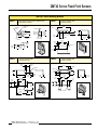
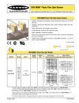
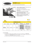
QMT42 Series Fixed-Field Sensors
Sensing Cutoff Point at 500, 750, 1000, 1500, or 2000 mm (20", 30", 39", 59" or 79")
QMT42 Series Fixed-Field Features
•
Fixed-field technology allows direct detection of objects within a defined sensing
field, while completely ignoring objects located beyond the sensing field cutoff
point
•
Compact, rugged, low cost self-contained sensors in metal die-cast housings
•
Leakproof IP67 (NEMA 6) construction for reliable sensing in harsh environments
•
Outstanding electrical noise immunity
•
Dual LED system indicates sensor performance
•
Choice of unterminated cable or quick-disconnect connector
Infrared, 880 nm
QMT42 Series Fixed-Field Mode
Cutoff
Point
Cable
QMT42VN6FF500
QMT42VN6FF500Q
500 mm
(20")
2 m (6.5')
4-pin Euro QD
NPN
QMT42VP6FF500
QMT42VP6FF500Q
500 mm
(20")
2 m (6.5')
4-pin Euro QD
PNP
QMT42VN6FF750
QMT42VN6FF750Q
750 mm
(30")
2 m (6.5')
4-pin Euro QD
NPN
750 mm
(30")
2 m (6.5')
4-pin Euro QD
PNP
2 m (6.5')
4-pin Euro QD
NPN
QMT42VP6FF1000
QMT42VP6FF1000Q
50 mm 1000 mm
(39")
(2.0") to
Cutoff 1000 mm
point
(39")
QMT42VN6FF1500
QMT42VN6FF1500Q
1500 mm
(59")
2 m (6.5')
4-pin Euro QD
NPN
QMT42VP6FF1500
QMT42VP6FF1500Q
1500 mm
(59")
2 m (6.5')
4-pin Euro QD
PNP
QMT42VN6FF2000
QMT42VN6FF2000Q
2000 mm
(79")
2 m (6.5')
4-pin Euro QD
NPN
QMT42VP6FF2000
QMT42VP6FF2000Q
2000 mm
(79")
2 m (6.5')
4-pin Euro QD
PNP
Models
QMT42VP6FF750
QMT42VP6FF750Q
QMT42VN6FF1000
QMT42VN6FF1000Q
Printed in USA
Range
2 m (6.5')
4-pin Euro QD
Supply
Voltage
Output
Type
10-30V dc
PNP
Performance Curves
1000
QMT42FF
Series
E
X
C
E 100
S
S
G
A
I
N
500 mm
750 mm
1000 mm
1500 mm
2000 mm
10
1
10 mm
.4 in
100 mm
4 in
1000 mm
40 in
10000 mm
400 in
DISTANCE
P/N 50756D9A
QMT42 Series Fixed-Field Sensors
Fixed-Field Sensing, Theory of Operation
A fixed-field sensor compares the reflections of its emitted light
beam (E) from a target object back to the sensor’s two
differently-aimed detectors (R1 and R2; see Figure 1). If the
near detector (R1) light signal is stronger than the far detector
(R2) light signal (object A is closer than the cutoff distance),
the sensor responds to the object. If the far detector (R2) light
signal is stronger than the near detector (R1) light signal
(object B is beyond the cutoff distance), the sensor ignores the
object. At the cutoff distance (dashed line), the signals from the
two detectors are equal. Objects lying beyond the cutoff distance
are ignored, even if they are highly reflective, (see below).
However, it is possible to falsely detect a background object, if
it is positioned as shown in Figure 3, or if it moves past the
face of the sensor in a direction perpendicular to the sensing
axis (and especially if it has a reflective surface; see Figures 2
and 3). To solve this problem, rotate the sensor 90º, as shown
in Figure 4.
Cutoff
Distance
Object
A
Near
Detector
Lenses
R1
Far
Detector
R2
Emitter
E
Object
B
Object is
sensed if the
amount of
light at R1 is
greater than
the amount
of light at
R2.
Background
Sensing Field
Figure 1. Fixed-field sensing, theory of operation
Receiver
Element
As a general rule when an object
approaches from the side, the
most reliable sensing occurs
Sensing Axis when the line of approach is
parallel to the sensing axis.
Emitter
Figure 2. Sensing axis
Cutoff Distance
Sensor
(side view)
An object in this
position or moving
across the sensor
face in this axis and
direction may cause
false sensor
response.
Sensing Field
Figure 3. Object beyond cutoff distance (problem)
Cutoff Distance
Sensor (top view)
An object in this
position or moving
across the sensor
face in this axis
will be ignored.
Sensing Field
Figure 4. Object beyond cutoff distance (solution)
page 2
Banner Engineering Corp. • Minneapolis, U.S.A.
Website: http://www.baneng.com • Tel: 612.544.3164
QMT42 Series Fixed-Field Sensors
QMT42 Series Fixed-Field Mode Specification
Sensing Beam
Infrared, 880 nm
Supply Voltage and Current
10 to 30V dc (10% maximum ripple) at less than 40 milliamps
Supply Protection Circuitry
Protected against reverse polarity and transient voltages
Output Configuration
SPDT (complementary) solid-state dc switch; choose NPN (current sinking) or PNP (current sourcing) models.
Light operate: N.O. output conducts when the sensor sees its own modulated light
Dark operate: N.C. output conducts when the sensor sees dark
Output Rating
100 mA maximum (each output)
OFF-state leakage current: < 5 microamps at 30V dc
ON-state saturation voltage: < 1V at 10 mA dc; < 1.5V at 100 mA dc
Output Protection Circuitry
Protected against false pulse on power-up and continuous overload or short-circuit of outputs
Overload trip point ≥ 150mA, typical, at 20ºC
Output Response Time
1 millisecond on and off
NOTE: 100 millisecond delay on power-up; outputs are non-conducting during this time
Repeatability of Response
250 microseconds
Sensing Hysteresis
Less than 5% of cutoff distance - 2000 mm models
Less than 4% of cutoff distance - 1500 mm models
Less than 3% of cutoff distance - 1000 mm models
Less than 2% of cutoff distance - 750 mm models
Less than 1% of cutoff distance - 500 mm models
Cutoff Point Tolerance
±10% of nominal cutoff distance
Indicators
Two LEDs: Green and Yellow
GREEN glowing steadily
GREEN flashing
YELLOW glowing steadily
YELLOW flashing
=
=
=
=
power to sensor is ON
output is overloaded
light is sensed; normally open output ON
marginal excess gain (1-1.5x) in light condition
Construction
Housings are die-cast zinc alloy with black acrylic polyurethane finish; lenses are acrylic
Environmental Rating
IP67; NEMA 6
Connections
2 m (6.5') or 9 m (30') attached cable, or 4-pin Euro-style quick-disconnect fitting; cables for QD models
are purchased separately
Operating Conditions
Temperature: -20º to +55ºC (-4º to 131ºF)
Maximum relative humidity: 90% at 50ºC (non-condensing)
Certifications
Interpretation of Cutoff Point Deviation Curve
The percentage of deviation indicates a change in the cutoff
point for either 18% gray or 6% black targets, relative to the
cutoff point for a 90% reflective white test card.
+10
Cutoff Point Deviation
+8
+6
+4
+2
18% Gray Color Sensitivity
6 % Black Color Sensitivity
0
Percent
Deviation -2
-4
-6
-8
As an example, the cutoff point decreases 10% for a 6%
reflectance black target when the cutoff point is 2000
millimeters (79") using a 90% reflectance white test card. In
other words, the cutoff point for the black target is 1800
millimeters (71").
-10
0
500 mm
(20 in)
750 mm
(30 in)
1000 mm
(39 in)
1500 mm
(59 in)
2000 mm
(79 in)
Cutoff Point Variation Relative to 90% Reflectance White Test Card
Banner Engineering Corp. • Minneapolis, U.S.A.
Website: http://www.baneng.com • Tel: 612.544.3164
page 3
QMT42 Series Fixed-Field Sensors
QMT42 Series Dimensions
Quick-Disconnect models
Cabled Models
18.0 mm
(0.71")
Green LED Power/Overload Indicator
Yellow LED
Output/Marginal Indicator
19.2 mm
(0.76")
ø 3.2 mm
(0.125")
(4 Holes)
58.0 mm
(2.28")
76.2 mm
(3.00")
M12 x 1 x 18 mm
Euro-style
2 x 3.1mm
(0.12")
10.0 mm (0.39")
2 x 3.1mm
(0.12")
12.3 mm (0.48")
23.9 mm (2)
(0.94")
27.1 mm (2)
(1.07")
42.0 mm
(1.65")
Threaded M4 x 0.7
Mounting Holes
QMT42 Series Hookup Diagrams
Sensors with NPN (Sinking) Outputs
Cabled Models
bu
bn
bk
wh
Sensors with PNP (Sourcing) Outputs
Cabled Models
Quick-Disconnect Models
-
10-30V dc
+
Load
Load
bn
bu
bk
wh
bu
10-30V dc
bn
+
bk
Load
wh
Load
Quick-Disconnect Models
bn
+
10-30V dc
bu
bk
Load
wh
+
10-30V dc
-
Load
Load
Load
Accessories
Quick-Disconnect (QD) Cables
Style
4-pin
Euro-style
straight
Model
Length
MQDC-406
MQDC-415
MQDC-430
2 m (6.5')
5 m (15')
9 m (30')
Dimensions
Pinout
ø15 mm
(0.6")
44 mm max.
(1.7")
M12 x 1
Pin #1
Brown Wire
38 mm max.
(1.5")
4-pin Euro-syle
right-angle
MQDC-406RA
MQDC-415RA
MQDC-430RA
2 m (6.5')
5 m (15')
9 m (30')
Pin #4
Black Wire
Pin #2
White Wire
Pin #3
Blue Wire
38 mm max.
(1.5")
M12 x 1
ø15 mm
(0.6")
page 4
Banner Engineering Corp. • Minneapolis, U.S.A.
Website: http://www.baneng.com • Tel: 612.544.3164
QMT42 Series Fixed-Field Sensors
QMT42FF Series Mounting Brackets
SMB42T
• Right-angle mounting bracket, stainless steel
• M3 hardware included
4x M4 x 0.7
10° (TYP)
15°
(2)
CL 31.8 mm
(1.25")
4.32 mm
(0.170")
Slot (2)
5.0 mm
(0.20")
ø 3.05 mm Slot
(0.120")
90°
6.4 mm
(0.25")
20.3 mm
(0.80")
20°
ø 3.05 mm
(0.120")
• 13 gauge stainless steel
• Hardware included
40.0 mm
(1.58")
R 24.1 mm
(0.95")
R 5.1 mm
(0.20")
SMB42L
R 3.1 mm
(0.12") (2)
3.0 mm
(0.12")
20.1 mm
(0.79")
12.7 mm
(0.50")
2.3 mm
(0.09")
3x 10.0 mm
(0.40")
23.3 mm
(0.92")
33.0 mm
(1.30")
25.4 mm
(1.00")
2x M3 x 0.5
2.5 mm
(0.10")
SMB42F
45.5 mm
(1.79")
9.6 mm
(0.38")
• 13 gauge stainless steel
• Hardware included
5.0 mm
(0.20")
SMB42U
10.0 mm
(0.40")
• 13 gauge stainless steel
• Hardware included
38.9 mm
(1.53")
2x M4 x 0.7
2x 8.9 mm
(0.35")
2x M4 x 0.7
6.5 mm
(0.25")
12.7 mm
(0.50")
20.0 mm
(0.79")
28.3 mm
(1.12")
9.6 mm
(0.38")
6.4 mm
(0.25")
2.3 mm
(0.09")
3.1 mm
(0.12")
25.4 mm
(1.00")
25.4 mm
(1.00")
12.7 mm
(0.50")
12.7 mm
(0.50")
12.7 mm
(0.50")
30.0 mm
(1.18")
25.4 mm
(1.00")
25.4 mm
(1.00")
23.3 mm
(0.92")
2.3 mm
(0.09")
3.1 mm
(0.12")
9.6 mm
(0.38")
23.3 mm
(0.92")
4x M3 x 0.5
4x M3 x 0.5
37.1 mm
(1.46")
48.4 mm
(1.91")
Banner Engineering Corp. • Minneapolis, U.S.A.
Website: http://www.baneng.com • Tel: 612.544.3164
page 5
QMT42 Series Fixed-Field Sensors
WARRANTY: Banner Engineering Corp. warrants its products to be free from defects for one year. Banner Engineering Corp. will repair or
replace, free of charge, any product of its manufacture found to be defective at the time it is returned to the factory during the warranty
period. This warranty does not cover damage or liability for the improper application of Banner products. This warranty is in lieu of any
other warranty either expressed or implied.
!
WARNING . . .
Not To Be Used for Personnel Protection
Never use these products as sensing devices for personnel protection. Doing so could lead to serious injury or death.
These sensors do NOT include the self-checking redundant circuitry necessary to allow their use in personnel safety
applications. A sensor failure or malfunction can cause either an energized or de-energized sensor output condition. Consult your current
Banner Safety Products catalog for safety products which meet OSHA, ANSI and IEC standards for personnel protection.
Banner Engineering Corp., 9714 Tenth Ave. No., Minneapolis, MN 55441 • Phone: 612.544.3164 • Fax: 612.544.3213 • E-mail: sensors@baneng.com