1
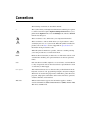
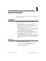
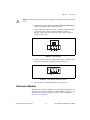
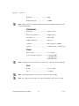
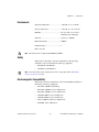
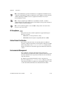
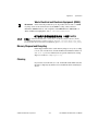
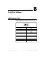
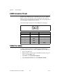
TPC-2206/TPC-2212/ TPC-2215 User Manual TPC-2206/TPC-2212/TPC-2215 User Manual October 2011 373297B-01 Support Worldwide Technical Support and Product Information ni.com Worldwide Offices Visit ni.com/niglobal to access the branch office Web sites, which provide up-to-date contact information, support phone numbers, email addresses, and current events. National Instruments Corporate Headquarters 11500 North Mopac Expressway Austin, Texas 78759-3504 USA Tel: 512 683 0100 For further support information, refer to the Technical Support and Professional Services appendix. To comment on National Instruments documentation, refer to the National Instruments Web site at ni.com/info and enter the Info Code feedback. © 2010–2011 National Instruments Corporation. All rights reserved. Important Information Warranty The TPC-2206, TPC-2212, and TPC-2215 are warranted against defects in materials and workmanship for a period of one year from the date of shipment, as evidenced by receipts or other documentation. National Instruments will, at its option, repair or replace equipment that proves to be defective during the warranty period. This warranty includes parts and labor. The media on which you receive National Instruments software are warranted not to fail to execute programming instructions, due to defects in materials and workmanship, for a period of 90 days from date of shipment, as evidenced by receipts or other documentation. National Instruments will, at its option, repair or replace software media that do not execute programming instructions if National Instruments receives notice of such defects during the warranty period. National Instruments does not warrant that the operation of the software shall be uninterrupted or error free. A Return Material Authorization (RMA) number must be obtained from the factory and clearly marked on the outside of the package before any equipment will be accepted for warranty work. National Instruments will pay the shipping costs of returning to the owner parts which are covered by warranty. National Instruments believes that the information in this document is accurate. The document has been carefully reviewed for technical accuracy. In the event that technical or typographical errors exist, National Instruments reserves the right to make changes to subsequent editions of this document without prior notice to holders of this edition. The reader should consult National Instruments if errors are suspected. In no event shall National Instruments be liable for any damages arising out of or related to this document or the information contained in it. EXCEPT AS SPECIFIED HEREIN, NATIONAL INSTRUMENTS MAKES NO WARRANTIES, EXPRESS OR IMPLIED, AND SPECIFICALLY DISCLAIMS ANY WARRANTY OF MERCHANTABILITY OR FITNESS FOR A PARTICULAR PURPOSE. CUSTOMER’S RIGHT TO RECOVER DAMAGES CAUSED BY FAULT OR NEGLIGENCE ON THE PART OF NATIONAL INSTRUMENTS SHALL BE LIMITED TO THE AMOUNT THERETOFORE PAID BY THE CUSTOMER. NATIONAL INSTRUMENTS WILL NOT BE LIABLE FOR DAMAGES RESULTING FROM LOSS OF DATA, PROFITS, USE OF PRODUCTS, OR INCIDENTAL OR CONSEQUENTIAL DAMAGES, EVEN IF ADVISED OF THE POSSIBILITY THEREOF. This limitation of the liability of National Instruments will apply regardless of the form of action, whether in contract or tort, including negligence. Any action against National Instruments must be brought within one year after the cause of action accrues. National Instruments shall not be liable for any delay in performance due to causes beyond its reasonable control. The warranty provided herein does not cover damages, defects, malfunctions, or service failures caused by owner’s failure to follow the National Instruments installation, operation, or maintenance instructions; owner’s modification of the product; owner’s abuse, misuse, or negligent acts; and power failure or surges, fire, flood, accident, actions of third parties, or other events outside reasonable control. Copyright Under the copyright laws, this publication may not be reproduced or transmitted in any form, electronic or mechanical, including photocopying, recording, storing in an information retrieval system, or translating, in whole or in part, without the prior written consent of National Instruments Corporation. National Instruments respects the intellectual property of others, and we ask our users to do the same. NI software is protected by copyright and other intellectual property laws. Where NI software may be used to reproduce software or other materials belonging to others, you may use NI software only to reproduce materials that you may reproduce in accordance with the terms of any applicable license or other legal restriction. Trademarks LabVIEW, National Instruments, NI, ni.com, the National Instruments corporate logo, and the Eagle logo are trademarks of National Instruments Corporation. Refer to the Trademark Information at ni.com/trademarks for other National Instruments trademarks. Other product and company names mentioned herein are trademarks or trade names of their respective companies. Members of the National Instruments Alliance Partner Program are business entities independent from National Instruments and have no agency, partnership, or joint-venture relationship with National Instruments. Patents For patents covering National Instruments products/technology, refer to the appropriate location: Help»Patents in your software, the patents.txt file on your media, or the National Instruments Patent Notice at ni.com/patents. Export Compliance Information Refer to the Export Compliance Information at ni.com/legal/export-compliance for the National Instruments global trade compliance policy and how to obtain relevant HTS codes, ECCNs, and other import/export data. WARNING REGARDING USE OF NATIONAL INSTRUMENTS PRODUCTS (1) NATIONAL INSTRUMENTS PRODUCTS ARE NOT DESIGNED WITH COMPONENTS AND TESTING FOR A LEVEL OF RELIABILITY SUITABLE FOR USE IN OR IN CONNECTION WITH SURGICAL IMPLANTS OR AS CRITICAL COMPONENTS IN ANY LIFE SUPPORT SYSTEMS WHOSE FAILURE TO PERFORM CAN REASONABLY BE EXPECTED TO CAUSE SIGNIFICANT INJURY TO A HUMAN. (2) IN ANY APPLICATION, INCLUDING THE ABOVE, RELIABILITY OF OPERATION OF THE SOFTWARE PRODUCTS CAN BE IMPAIRED BY ADVERSE FACTORS, INCLUDING BUT NOT LIMITED TO FLUCTUATIONS IN ELECTRICAL POWER SUPPLY, COMPUTER HARDWARE MALFUNCTIONS, COMPUTER OPERATING SYSTEM SOFTWARE FITNESS, FITNESS OF COMPILERS AND DEVELOPMENT SOFTWARE USED TO DEVELOP AN APPLICATION, INSTALLATION ERRORS, SOFTWARE AND HARDWARE COMPATIBILITY PROBLEMS, MALFUNCTIONS OR FAILURES OF ELECTRONIC MONITORING OR CONTROL DEVICES, TRANSIENT FAILURES OF ELECTRONIC SYSTEMS (HARDWARE AND/OR SOFTWARE), UNANTICIPATED USES OR MISUSES, OR ERRORS ON THE PART OF THE USER OR APPLICATIONS DESIGNER (ADVERSE FACTORS SUCH AS THESE ARE HEREAFTER COLLECTIVELY TERMED “SYSTEM FAILURES”). ANY APPLICATION WHERE A SYSTEM FAILURE WOULD CREATE A RISK OF HARM TO PROPERTY OR PERSONS (INCLUDING THE RISK OF BODILY INJURY AND DEATH) SHOULD NOT BE RELIANT SOLELY UPON ONE FORM OF ELECTRONIC SYSTEM DUE TO THE RISK OF SYSTEM FAILURE. TO AVOID DAMAGE, INJURY, OR DEATH, THE USER OR APPLICATION DESIGNER MUST TAKE REASONABLY PRUDENT STEPS TO PROTECT AGAINST SYSTEM FAILURES, INCLUDING BUT NOT LIMITED TO BACK-UP OR SHUT DOWN MECHANISMS. BECAUSE EACH END-USER SYSTEM IS CUSTOMIZED AND DIFFERS FROM NATIONAL INSTRUMENTS' TESTING PLATFORMS AND BECAUSE A USER OR APPLICATION DESIGNER MAY USE NATIONAL INSTRUMENTS PRODUCTS IN COMBINATION WITH OTHER PRODUCTS IN A MANNER NOT EVALUATED OR CONTEMPLATED BY NATIONAL INSTRUMENTS, THE USER OR APPLICATION DESIGNER IS ULTIMATELY RESPONSIBLE FOR VERIFYING AND VALIDATING THE SUITABILITY OF NATIONAL INSTRUMENTS PRODUCTS WHENEVER NATIONAL INSTRUMENTS PRODUCTS ARE INCORPORATED IN A SYSTEM OR APPLICATION, INCLUDING, WITHOUT LIMITATION, THE APPROPRIATE DESIGN, PROCESS AND SAFETY LEVEL OF SUCH SYSTEM OR APPLICATION. Compliance Electromagnetic Compatibility Information This hardware has been tested and found to comply with the applicable regulatory requirements and limits for electromagnetic compatibility (EMC) as indicated in the hardware’s Declaration of Conformity (DoC)1. These requirements and limits are designed to provide reasonable protection against harmful interference when the hardware is operated in the intended electromagnetic environment. In special cases, for example when either highly sensitive or noisy hardware is being used in close proximity, additional mitigation measures may have to be employed to minimize the potential for electromagnetic interference. While this hardware is compliant with the applicable regulatory EMC requirements, there is no guarantee that interference will not occur in a particular installation. To minimize the potential for the hardware to cause interference to radio and television reception or to experience unacceptable performance degradation, install and use this hardware in strict accordance with the instructions in the hardware documentation and the DoC1. If this hardware does cause interference with licensed radio communications services or other nearby electronics, which can be determined by turning the hardware off and on, you are encouraged to try to correct the interference by one or more of the following measures: • Reorient the antenna of the receiver (the device suffering interference). • Relocate the transmitter (the device generating interference) with respect to the receiver. • Plug the transmitter into a different outlet so that the transmitter and the receiver are on different branch circuits. Some hardware may require the use of a metal, shielded enclosure (windowless version) to meet the EMC requirements for special EMC environments such as, for marine use or in heavy industrial areas. Refer to the hardware’s user documentation and the DoC1 for product installation requirements. When the hardware is connected to a test object or to test leads, the system may become more sensitive to disturbances or may cause interference in the local electromagnetic environment. Operation of this hardware in a residential area is likely to cause harmful interference. Users are required to correct the interference at their own expense or cease operation of the hardware. Changes or modifications not expressly approved by National Instruments could void the user’s right to operate the hardware under the local regulatory rules. 1 The Declaration of Conformity (DoC) contains important EMC compliance information and instructions for the user or installer. To obtain the DoC for this product, visit ni.com/certification, search by model number or product line, and click the appropriate link in the Certification column. Conventions The following conventions are used in this manual: » The » symbol leads you through nested menu items and dialog box options to a final action. The sequence Options»Settings»General directs you to pull down the Options menu, select the Settings item, and select General from the last dialog box. This icon denotes a note, which alerts you to important information. This icon denotes a caution, which advises you of precautions to take to avoid injury, data loss, or a system crash. When this symbol is marked on a product, refer to the Safety section of Appendix A, Specifications, for information about precautions to take. When this symbol is marked on a product, it denotes a warning advising you to take precautions to avoid electrical shock. bold Bold text denotes items that you must select or click in the software, such as menu items and dialog box options. Bold text also denotes parameter names. italic Italic text denotes variables, emphasis, a cross-reference, or an introduction to a key concept. Italic text also denotes text that is a placeholder for a word or value that you must supply. monospace Text in this font denotes text or characters that you should enter from the keyboard, sections of code, programming examples, and syntax examples. This font is also used for the proper names of disk drives, paths, directories, programs, subprograms, subroutines, device names, functions, operations, variables, filenames, and extensions. TPC-22xx Wherever this reference appears, the information applies to all three versions of the TPC-22xx Human Machine Interface (HMI): the TPC-2206, TPC-2212, and TPC-2215. Contents Chapter 1 General Information Introduction....................................................................................................................1-1 I/O Ports .........................................................................................................................1-1 Chapter 2 System Setup Important Safety Information ........................................................................................2-1 Setup ..............................................................................................................................2-2 Touchscreen Calibration..................................................................................2-3 Panel Mounting..............................................................................................................2-4 Chapter 3 Jumpers and Connectors Jumper and Connector Functions ..................................................................................3-1 Jumper and Connector Locations ..................................................................................3-3 Appendix A Specifications Appendix B Serial Port Settings Appendix C Features in Windows XP Embedded and Windows Embedded Standard 7 Appendix D Touchscreen Configuration Appendix E Technical Support and Professional Services Index © National Instruments Corporation vii TPC-2206/TPC-2212/TPC-2215 User Manual 1 General Information This chapter includes general information about the TPC-22xx Human Machine Interface (HMI). Introduction The TPC-22xx touch panel computer, an HMI based on an x86 platform, includes these key features: • Powerful processing—The TPC-22xx uses the Intel Atom processor, specifically designed for embedded, industrial applications. • Fanless—By using an advanced but low-power Intel Atom processor, the TPC-22xx does not require a fan for cooling. • Robust communication—The TPC-22xx is a powerful I/O interface for easy communication with other devices. The I/O interface includes serial ports, gigabit Ethernet, and USB 2.0 support. • Wide operating temperature and isolation protection—The TPC-22xx provides a –20 to 60 °C operating temperature range and complete isolation protection for the serial ports. • Windows Embedded support—The TPC-22xx supports the latest embedded Windows operating systems from Microsoft, including Windows XP Embedded (XPe) and Windows Embedded Standard 7 (WES7). I/O Ports The TPC-22xx includes the following ports: • Two serial ports: RS232 (COM1) and RS422/485 (COM2) • Two USB 2.0 ports compliant with USB 1.0 and 1.1 • Two RJ-45 Gigabit Ethernet ports © National Instruments Corporation 1-1 TPC-2206/TPC-2212/TPC-2215 User Manual Chapter 1 General Information Figure 1-1 shows the I/O port arrangement. 1 1 2 LAN 1 LAN 2 2 3 4 3 5 4 USB COM2 (RS422/485) 5 COM1 (RS232) Figure 1-1. I/O Port Arrangement For more TPC-22xx specifications, refer to Appendix A, Specifications. TPC-2206/TPC-2212/TPC-2215 User Manual 1-2 ni.com 2 System Setup This chapter includes setup information for the TPC-22xx. Important Safety Information Before setting up the TPC-22xx, read these safety instructions carefully. Disconnect this equipment from any AC outlet before cleaning. Use a damp cloth. Do not use liquid or spray detergents for cleaning. For plug-in equipment, the power outlet socket must be located near the equipment and must be easily accessible. Keep this equipment away from excessive humidity. Place this equipment on a reliable surface during installation. Dropping it or letting it fall may cause damage. The openings on the enclosure are for air convection and protect the equipment from overheating. Do not cover the openings. Make sure the power source voltage is correct before connecting the equipment to the power outlet. Position the power cord so that it cannot be stepped on. Do not place anything over the power cord. All cautions and warnings on the equipment should be noted. If the equipment is not used for a long time, disconnect it from the power source to avoid damage by transient overvoltage. Never pour any liquid into an opening. This may cause fire or electrical shock. Never open the equipment. For safety reasons, only qualified service personnel should open the equipment. © National Instruments Corporation 2-1 TPC-2206/TPC-2212/TPC-2215 User Manual Chapter 2 System Setup If one of the following situations arises, have service personnel check the equipment: • The power cord or plug is damaged. • Liquid has penetrated into the equipment. • The equipment has been exposed to moisture. • The equipment does not work well, or you cannot get it to work according to the user manual. • The equipment has been dropped and damaged. • The equipment has obvious signs of breakage. Do not leave this equipment in an environment where the storage temperature may go below –30 °C (–22 °F) or above 80 °C (176 °F). Doing so could damage the equipment. The equipment should be in a controlled environment. Caution There is a danger of explosion if the battery is incorrectly replaced. Replace the battery only with the same or equivalent type recommended by the manufacturer. Discard used batteries according to the manufacturer’s instructions. The sound pressure level at the operator’s position according to IEC 704-1:1982 is no more than 70 dB (A). Caution The protection this equipment provides may be impaired if it is used in a manner not described in this manual. Setup Follow these steps to set up the TPC-22xx: 1. Unpack the TPC-22xx. Be sure your kit includes the following items: • The TPC-22xx HMI • Six panel mounting clamps (TPC-2206) • Six panel mounting screws (TPC-2206) • Eight panel mounting clamps (TPC-2212 and TPC-2215) • Eight panel mounting screws (TPC-2212 and TPC-2215) • One 3-pin power connector • One HMI Resource CD • One earth ground cable If any items are missing or damaged, contact National Instruments. TPC-2206/TPC-2212/TPC-2215 User Manual 2-2 ni.com Chapter 2 Caution System Setup Be sure system power is off before plugging in or pulling out the CompactFlash card. 2. Verify that the CompactFlash card containing Windows Embedded or another operating system is installed in the unit. 3. Connect the power connector to an 18–32 VDC power line. Be sure to connect the positive, negative, and ground lines as shown in Figure 2-1. The power lines can be from either a power adapter or in-house power source. + – GND Figure 2-1. Power Connector 4. Connect the power connector to the power receptor on the TPC-22xx. The power receptor pin assignment is shown in Figure 2-2. GND – + Figure 2-2. Power Receptor and Pin Assignment 5. The system turns on immediately after you apply power. Touchscreen Calibration The TPC-22xx touchscreen should be correctly calibrated and ready to use when you power on the system. However, if the calibration is not correct or you want to choose custom calibration options, refer to Appendix D, Touchscreen Configuration. © National Instruments Corporation 2-3 TPC-2206/TPC-2212/TPC-2215 User Manual Chapter 2 System Setup Panel Mounting Follow these steps to mount the TPC-22xx in a panel: Note 1. Be sure the adhesive waterproof gasket on the front bezel is in position. 2. Install the TPC-22xx in the panel opening. (Refer to Appendix A, Specifications, for cutout dimensions.) 3. Hook the clamps included in the accessory pack to the holes around the four sides of the bezel. Be sure to remove the protective inserts in the panel mounting holes. 4. Insert the screws included in the accessory pack into the clamps. To fasten the TPC-22xx to the panel, tighten the screws so they push against the mounting panel. The mounting panel thickness should be less than 6 mm (0.236 in.). TPC-2206/TPC-2212/TPC-2215 User Manual 2-4 ni.com 3 Jumpers and Connectors This chapter describes the TPC-22xx jumpers and connectors. Jumper and Connector Functions Table 3-1 lists the jumper and connector functions. Table 3-1. Mainboard Connectors and Jumpers Label © National Instruments Corporation Function Description BH1 Battery RTC battery bracket CN1 LAN2 Gigabit Ethernet: LAN2 CN2 LAN1 Gigabit Ethernet: LAN1 CN3 LCD Power LCD power connection CN4 LCD Power LCD power voltage CN5 LVDS LVDS video connection CN6/CN7 CompactFlash CompactFlash bracket CN8 USB2 Two USB type-A female CN11 COM1 Serial port: COM1 RS232 CN12 COM2 Serial port: COM2 RS422/485 CN13 DC in DC power in connector (5.08 mm, 3-pin housing) CN16 CMOS CMOS clear select CN17 IDE AT mode select CN18 Touchscreen Touchscreen interface FS1 Fuse Fuse bracket SODIMM1 RAM DDR2 SODIMM bracket 3-1 TPC-2206/TPC-2212/TPC-2215 User Manual Chapter 3 Jumpers and Connectors Table 3-1. Mainboard Connectors and Jumpers (Continued) Label Function Description SW1 LCD Resolution LCD resolution select SW2 LCD Function LCD controlled function SW3 Touchscreen Touchscreen type SW4 Termination Serial termination resistor U2 CPU CPU U4 SCH System controller hub U12 BIOS BIOS chip TPC-2206/TPC-2212/TPC-2215 User Manual 3-2 ni.com Chapter 3 Jumpers and Connectors Jumper and Connector Locations Figures 3-1 and 3-2 show the jumper and connector locations. CN3 SW3 CN18 U2 CN15 CN5 SODIMM1 CN4 CN9 SW2 CN10 U4 BH1 CN17 CN16 SW1 CN1 CN8 FS1 CN13 SW4 CN11 CN2 CN12 Figure 3-1. Main Board Jumpers and Connectors—Top Side © National Instruments Corporation 3-3 TPC-2206/TPC-2212/TPC-2215 User Manual Chapter 3 Jumpers and Connectors CN6 CN7 U12 SW4 Figure 3-2. Main Board Jumpers and Connectors—Bottom Side TPC-2206/TPC-2212/TPC-2215 User Manual 3-4 ni.com A Specifications This appendix lists the TPC-22xx system specifications. Physical TPC-2206 Weight .................................................... 1.43 kg Dimensions (W × H × D)....................... 195 × 148 × 58 mm (7.68 × 5.83 × 2.28 in.) Cutout dimensions.................................. 189.1 × 142.1 mm (suggested) (7.44 × 5.59 in.) TPC-2212 Weight .................................................... 2.5 kg Dimensions (W × H × D)....................... 311 × 237 × 54 mm (12.24 × 9.33 × 2.13 in.) Cutout dimensions.................................. 302.5 × 228.5 mm (suggested) (11.91 × 9.00 in.) TPC-2215 Weight .................................................... 3 kg Dimensions (W × H × D)....................... 383 × 307 × 58.1 mm (15.08 × 12.09 × 2.29 in.) Cutout dimensions.................................. 374.5 × 298.5 mm (suggested) (14.74 × 11.75 in.) © National Instruments Corporation A-1 TPC-2206/TPC-2212/TPC-2215 User Manual Appendix A Specifications Dimensions (TPC-2206) 28.10 [1.11] 114.70 195.00 [4.52] [7.68] 132.00 [5.2] 86.10 [3.39] 6.00 [0.24] 148.00 [5.83] 6.00 [0.24] 6.00 [0.24] 58.00 [2.28] 70.50 [2.78] 188.10 [7.41] 141.10 [5.56] TPC-2206/TPC-2212/TPC-2215 User Manual A-2 ni.com Appendix A Specifications Dimensions (TPC-2212) 4.00 [0.16] 247.20 311.00 [9.73] [12.24] 180.00 [7.09] 6.50 [0.26] 186.30 [7.33] 237.00 [9.33] 3.50 [0.14] 170.00 [6.69] 6.50 [0.26] 54.00 [2.13] 4.00 [0.16] 301.50 [11.87] 227.50 [8.96] © National Instruments Corporation A-3 TPC-2206/TPC-2212/TPC-2215 User Manual Appendix A Specifications Dimensions (TPC-2215) 4.00 [0.16] 115.00 [4.53] 306.10 383.00 [12.05] [15.08] 115.00 [4.53] 7.00 [0.28] 230.10 [9.06] 307.00 [12.09] 4.50 [0.18] 236.00 [9.29] 7.00 [0.28] 58.10 [2.29] 4.00 [0.16] 374.50 [14.74] 298.50 [11.75] TPC-2206/TPC-2212/TPC-2215 User Manual A-4 ni.com Appendix A Specifications System CPU........................................................ Intel Atom Processor Z520PT 1.33 GHz w/HyperThreading SCH........................................................ Intel System Controller Hub US15WPT Video...................................................... Intel GMA 500 BIOS....................................................... Award 4 Mbit flash Ethernet .................................................. Realtek RTL8168C(P) × 2; 10/100/1000, IEEE 802.3ab protocol compatible RAM....................................................... 1 GB DDR2 Watchdog timer...................................... SCH3114X1watchdog timer; 1 to 255 s timeout period CompactFlash......................................... Ultra ATA/100, UDMA/100 compatible, 4 GB minimum LCD Display type ........................................... TFT LCD Size (diagonal) ....................................... 5.7 in. (TPC-2206) 12.1 in. (TPC-2212) 15 in. (TPC-2215) Maximum resolution .............................. 640 × 480 VGA (TPC-2206) 800 × 600 SVGA (TPC-2212) 1024 × 768 (TPC-2215) Maximum colors .................................... 262,000 Viewing angle ........................................ 160°/140° Luminance (cd/m2)................................. 700 (TPC-2206) 450 (TPC-2212) 350 (TPC-2215) Contrast ratio.......................................... 800:1 (TPC-2206) 700:1 (TPC-2212) 700:1 (TPC-2215) © National Instruments Corporation A-5 TPC-2206/TPC-2212/TPC-2215 User Manual Appendix A Specifications Backlight.................................................LED Backlight lifespan ...................................50,000 h There may be several bright or dark pixels on the LCD. This phenomenon is normal in LCD manufacturing. Note Touchscreen Touch type ..............................................Resistive 5-wire Base glass construction...........................Tempered glass Resolution ...............................................1024 × 1024 Light Transmission .................................80% ± 3% Controller................................................RS-232 interface (COM3) Lifespan ..................................................1 million touches at a single point Power Input voltage ...........................................18 to 32 VDC Power consumption (typical)..................17 W (TPC-2206) 35 W (TPC-2212) 40 W (TPC-2215) Note Providing power levels either below or above the stated range is not recommended. Fuse Rating......................................................T3.15 A, 250 V Size .........................................................5 × 20 mm Note When replacing the fuse, use only a fuse of the same type and rating. Note For your protection, the fuse is set to break if the input voltage exceeds 33 VDC. TPC-2206/TPC-2212/TPC-2215 User Manual A-6 ni.com Appendix A Specifications Environment Operating temperature............................ –20 to 60 °C (–4 to 140 °F) Storage temperature ............................... –30 to 80 °C (–22 to 176 °F) Humidity ................................................ 40 °C @ 10 to 95% relative humidity (noncondensing) Vibration ................................................ 2 grms (5 to 500 Hz) Maximum altitude .................................. 2,000 m Pollution Degree .................................... 2 Indoor use only Note The front bezel is compliant with NEMA4 and IP65. Safety This product is designed to meet the requirements of the following standards of safety for information technology equipment: • IEC 60950-1, EN 60950-1 • UL 60950-1, CSA 60950-1 Note For UL and other safety certifications, refer to the product label or the Online Product Certification section. Electromagnetic Compatibility This product meets the requirements of the following EMC standards for information technology equipment: • EN 55024 (CISPR 24); Immunity • EN 55022 (CISPR 22); Class A Emissions • EN 55011 (CISPR 11); Class A Emissions • AS/NZS CISPR 11; Class A Emissions • AS/NZS CISPR 22; Class A Emissions • FCC 47 CFR Part 15B: Class A Emissions • ICES-003: Class A Emissions © National Instruments Corporation A-7 TPC-2206/TPC-2212/TPC-2215 User Manual Appendix A Specifications In the United States (per FCC 47 CFR), Class A equipment is intended for use in commercial, light-industrial, and heavy-industrial locations. In Europe, Canada, Australia and New Zealand (per CISPR 11) Class A equipment is intended for use only in heavy-industrial locations. Note Group 1 equipment (per CISPR 11) is any industrial, scientific, or medical equipment that does not intentionally generate radio frequency energy for the treatment of material or inspection/analysis purposes. Note For the standards applied to assess the EMC of this product, refer to the Online Product Certification section. Note CE Compliance This product meets the essential requirements of applicable European Directives as follows: • 2006/95/EC; Low-Voltage Directive (safety) • 2004/108/EC; Electromagnetic Compatibility Directive (EMC) Online Product Certification Refer to the product Declaration of Conformity (DoC) for additional regulatory compliance information. To obtain product certifications and the DoC for this product, visit ni.com/certification, search by model number or product line, and click the appropriate link in the Certification column. Environmental Management NI is committed to designing and manufacturing products in an environmentally responsible manner. NI recognizes that eliminating certain hazardous substances from our products is beneficial to the environment and to NI customers. For additional environmental information, refer to the NI and the Environment Web page at ni.com/environment. This page contains the environmental regulations and directives with which NI complies, as well as other environmental information not included in this document. TPC-2206/TPC-2212/TPC-2215 User Manual A-8 ni.com Appendix A Specifications Waste Electrical and Electronic Equipment (WEEE) EU Customers At the end of the product life cycle, all products must be sent to a WEEE recycling center. For more information about WEEE recycling centers, National Instruments WEEE initiatives, and compliance with WEEE Directive 2002/96/EC on Waste and Electronic Equipment, visit ni.com/environment/weee. ⬉ᄤֵᙃѻક∵ᶧࠊㅵ⧚ࡲ⊩ ˄Ё RoHS˅ Ёᅶ᠋ National Instruments ヺড়Ё⬉ᄤֵᙃѻકЁ䰤ࠊՓ⫼ᶤѯ᳝ᆇ⠽䋼ᣛҸ (RoHS)DŽ ݇Ѣ National Instruments Ё RoHS ড়㾘ᗻֵᙃˈ䇋ⱏᔩ ni.com/environment/rohs_chinaDŽ (For information about China RoHS compliance, go to ni.com/environment/rohs_china.) Mercury Disposal and Recycling LCD lamp(s) in this monitor contain mercury. Dispose or recycle according to local, state or federal laws. Consult the Electronic Industries Alliance at www.eiae.org for more information. For specific information on lamp disposal, consult www.lamprecycle.org. Cleaning If you need to clean the unit, use a soft, nonmetallic brush. Make sure that the unit is completely dry and free from contaminants before returning it to service. © National Instruments Corporation A-9 TPC-2206/TPC-2212/TPC-2215 User Manual B Serial Port Settings This appendix describes the TPC-22xx serial port settings. COM1 Connector Pinout The TPC-22xx COM1 serial port is RS232 only. The following figure and table show the COM1 connector pinout. © National Instruments Corporation 1 5 6 9 Pin Signal 1 NDCD 2 NRX 3 NTX 4 NDTR 5 GND 6 NDSR 7 NRTS 8 NCTS 9 NRI B-1 TPC-2206/TPC-2212/TPC-2215 User Manual Appendix B Serial Port Settings COM2 Connector Pinout The TPC-22xx COM2 serial port is adjustable. You can set it to RS422 or RS485, and it has auto data flow control capability. In other words, the TPC-22xx can automatically detect the data flow direction at this port when two-wired RS485 communication is activated. The following figure and table show the COM2 pinout and settings. 1 5 6 9 PIN RS-422 RS-485 1 TX– D– 2 TX+ D+ 3 RX+ — 4 RX– — 5 GND GND COM2 Port Mode You must configure the TPC-22xx COM2 mode in the BIOS. Before performing the following steps, connect a USB keyboard to the TPC-22xx. 1. Power on the TPC-22xx. 2. While the unit is booting, but prior to the Windows splash screen, press <Del> to enter the BIOS setup. 3. In the BIOS, select Integrated Peripherals. 4. Under Serial Port 2 Mode, select either RS-422 or RS-485. TPC-2206/TPC-2212/TPC-2215 User Manual B-2 ni.com C Features in Windows XP Embedded and Windows Embedded Standard 7 The TPC-22xx supports the Windows XP Embedded platform (commonly abbreviated XPe), which is a componentized version of the Windows XP Professional edition, and Windows Embedded Standard 7 (WES7). EWF and FBWF Enhanced Write Filter (EWF) provides an upper filter in the storage device driver stack that redirects disk write operations to volatile (RAM) or nonvolatile (disk) storage. EWF protects a volume from write access and offers the following benefits: • Write-protects one or more partitions on your system. • Enables read-only media, such as CD-ROM or flash, to boot and run. • Prolongs the lifespan of write-sensitive storage, such as CompactFlash. File Based Write Filter (FBWF) also redirects disk write operations to volatile (RAM) or nonvolatile (disk) storage. Where EWF protects entire volumes from writes, FBWF protects only individual files and directories. Although FBWF is not as robust as EWF, because EWF protects entire volumes, it is very useful when you need to write to specific files and have those changes persist between reboots. You can enable and disable EWF and FBWF only between reboots. To disable/enable EWF/FBWF in Windows XP Embedded, go to Start»All Programs»Utilities and select the EWF tab. The default setting is disabled for both. To disable/enable EWF/FBWF in Windows Embedded Standard 7 (WES7), search for Info Code ewftpc on ni.com/info for more information. © National Instruments Corporation C-1 TPC-2206/TPC-2212/TPC-2215 User Manual Appendix C Features in Windows XP Embedded and Windows Embedded Standard 7 When EWF is enabled, the C: partition is protected from any disk writing. In this mode, any changes on the C: partition (including modifications to files or the registry) are redirected to memory. Thus, these changes are discarded in the next system startup. You can enable this mode manually after finishing all system changes such as installing your applications or adjusting system settings. HORM Hibernate Once, Resume Many (HORM) enables users to create a single hibernation file and boot to that file repeatedly. Using HORM, you can boot to a known state each time the system is powered on. HORM works only when EWF is enabled on all system partitions. HORM does not work with FBWF. Depending on the system state, HORM can reduce boot times. To enable HORM in Windows XP Embedded, you first must enable EWF as described in the EWF and FBWF section. Once enabled, return to the EWF utility at Start»All Programs»Utilities»EWF. Select the HORM tab and select HORM. This hibernates the system and creates the hibernation file. After you perform this step, all subsequent reboots resume from that hibernation file. To enable HORM is in Windows Embedded Standard 7 (WES7), search for Info Code ewftpc on ni.com/info for more information. You can programmatically control EWF, FBWF, and HORM using VIs included with the LabVIEW 2010 or later Touch Panel Module. Note Drivers The TPC-22xx is configured with all necessary drivers installed. If you need to reinstall any drivers, they are on the HMI Resources CD, which is included in the kit. TPC-2206/TPC-2212/TPC-2215 User Manual C-2 ni.com Touchscreen Configuration D This appendix explains how to configure the TPC-22xx touchscreen using the PenMount Control Panel. To calibrate the TPC-22xx, go to Start»All Programs»PenMount Windows Universal Driver»Utility»PenMount Control Panel. Select PenMount 6000 RS232 under Select a device to configure and click Configure. Here you can select either Standard Calibration or Advanced Calibration. Follow the onscreen instructions for either choice. © National Instruments Corporation D-1 TPC-2206/TPC-2212/TPC-2215 User Manual Technical Support and Professional Services E Visit the following sections of the award-winning National Instruments Web site at ni.com for technical support and professional services: • Support—Technical support at ni.com/support includes the following resources: – Self-Help Technical Resources—For answers and solutions, visit ni.com/support for software drivers and updates, a searchable KnowledgeBase, product manuals, step-by-step troubleshooting wizards, thousands of example programs, tutorials, application notes, instrument drivers, and so on. Registered users also receive access to the NI Discussion Forums at ni.com/forums. NI Applications Engineers make sure every question submitted online receives an answer. – Standard Service Program Membership—This program entitles members to direct access to NI Applications Engineers via phone and email for one-to-one technical support, as well as exclusive access to eLearning training modules at ni.com/ eLearning. NI offers complementary membership for a full year after purchase, after which you may renew to continue your benefits. For information about other technical support options in your area, visit ni.com/services, or contact your local office at ni.com/contact. • Training and Certification—Visit ni.com/training for training and certification program information. You can also register for instructor-led, hands-on courses at locations around the world. • System Integration—If you have time constraints, limited in-house technical resources, or other project challenges, National Instruments Alliance Partner members can help. To learn more, call your local NI office or visit ni.com/alliance. You also can visit the Worldwide Offices section of ni.com/niglobal to access the branch office Web sites, which provide up-to-date contact information, support phone numbers, email addresses, and current events. © National Instruments Corporation E-1 TPC-2206/TPC-2212/TPC-2215 User Manual Index C F CE compliance specifications, A-8 cleaning, A-9 COM1 connector pinout, B-1 COM2 connector mode, B-2 pinout, B-2 connectors, 3-1 function descriptions (table), 3-1 locations bottom side (table), 3-4 top side (table), 3-3 conventions used in the manual, v File Based Write Filter (FBWF), C-1 fuse specifications, A-6 H help, technical support, E-1 Hibernate Once, Resume Many (HORM), C-2 I I/O ports, 1-1 arrangement (figure), 1-2 instrument drivers (NI resources), E-1 introduction, 1-1 D diagnostic tools (NI resources), E-1 dimensions TPC-2206, A-2 TPC-2212, A-3 TPC-2215, A-4 documentation conventions used in the manual, v NI resources, E-1 drivers, C-2 NI resources, E-1 J jumpers, 3-1 function descriptions (table), 3-1 locations bottom side (table), 3-4 top side (table), 3-3 K KnowledgeBase, E-1 E L electromagnetic compatibility specifications, A-7 Enabled Write Filter (EWF), C-1 environmental management specifications, A-8 environmental specifications, A-7 examples (NI resources), E-1 © National Instruments Corporation LCD specifications, A-5 M mercury disposal and recycling specifications, A-9 I-1 TPC-2206/TPC-2212/TPC-2215 User Manual Index N physical, A-1 power, A-6 safety, A-7 system, A-5 touchscreen, A-6 Waste Electrical and Electronic Equipment, A-9 support, technical, E-1 system setup, 2-2 system specifications, A-5 NI support and services, E-1 O online product certification specifications, A-8 P panel mounting, 2-4 physical specifications, A-1 pinouts COM1 connector, B-1 COM2 connector, B-2 power connector (figure), 2-3 power receptor (figure), 2-3 power specifications, A-6 programming examples (NI resources), E-1 T technical support, E-1 touchscreen calibration, 2-3, D-1 specifications, A-6 TPC-2206/TPC-2212/TPC-2215 CE compliance specifications, A-8 cleaning specifications, A-9 COM1 connector pinout, B-1 COM2 connector mode, B-2 pinout, B-2 connectors, 3-1 dimensions TPC-2206, A-2 TPC-2212, A-3 TPC-2215, A-4 drivers, C-2 electromagnetic compatibility specifications, A-7 Enable Write Filter (EWF), C-1 environmental management specifications, A-8 environmental specifications, A-7 File Based Write Filter (FBWF), C-1 fuse specifications, A-6 Hibernate Once, Resume Many (HORM), C-2 I/O ports, 1-1 S safety information, 2-1 specifications, A-7 serial port settings, B-1 setup, 2-2 software (NI resources), E-1 specifications, A-1 CE compliance, A-8 cleaning, A-9 dimensions TPC-2206, A-2 TPC-2212, A-3 TPC-2215, A-4 electromagnetic compatibility, A-7 environmental, A-7 environmental management, A-8 fuse, A-6 LCD, A-5 mercury disposal and recycling, A-9 online product certification, A-8 TPC-2206/TPC-2212/TPC-2215 User Manual I-2 ni.com Index W introduction, 1-1 jumpers, 3-1 LCD specifications, A-5 mercury disposal and recycling specifications, A-9 online product certification specifications, A-8 panel mounting, 2-4 physical specifications, A-1 power connector (figure), 2-3 power receptor (figure), 2-3 power specifications, A-6 safety information, 2-1 specifications, A-7 serial port settings, B-1 specifications, A-1 system setup, 2-2 system specifications, A-5 touchscreen calibration, 2-3, D-1 specifications, A-6 Waste Electrical and Electronic Equipment specifications, A-9 Windows XP Embedded/Windows Embedded Standard 7 features, C-1 training and certification (NI resources), E-1 troubleshooting (NI resources), E-1 © National Instruments Corporation Waste Electrical and Electronic Equipment specifications, A-9 Web resources, E-1 Windows XP Embedded/Windows Embedded Standard 7 features, C-1 I-3 TPC-2206/TPC-2212/TPC-2215 User Manual