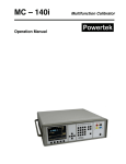
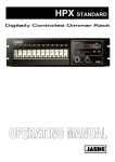
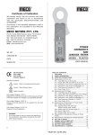
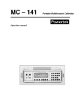
1
AUTOMATIC POWER FACTOR CONTROLLER APFC-03 - USER MANUAL TAS POWERTEK PVT.LTD. VERSION 1.1 Page 1 of 55 Updated on: FEB. 16, 2015. NOTE These instructions do not purport to cover all details or variations in equipment, nor to provide for every possible contingency to be met in connection with installation, operation or maintenance. Should further information be desired or should particular problems arise which are not covered sufficiently for the purchasers purposes, the matter should be referred to our factory. The contents of this User Manual shall not become part of or modify any prior or existing agreement or relationship. Any statements contained herein do not create new warranties or modify the existing warranty. The reproduction, transmission or use of this document or its contents is not permitted without express written authority. Offenders will be liable for damages. All rights are reserved. CAUTIONS: 1. High voltage 2. APFC only be used indoor 3. Make sure that the discharge time set in the controller matches the capacitor discharge time 4. This User Manual corresponds to the APFC-03Controller, Firmware Version 1.0.2. Because of continuous improvements efforts by TAS PowerTek in their Product‟s Features and Specifications, the Product as well as the content of the User Manual is likely to get updated. Therefore, please always refer to the User Manual supplied to the customer along with the Product, at the time of product dispatch. TAS POWERTEK PVT.LTD. VERSION 1.1 Page 2 of 55 Updated on: FEB. 16, 2015. INDEX 1. Index Page --- 3 2. Features --- 4 3. Specifications --- 6 4. Mechanical Dimensions --- 7 5. Terminal Arrangement --- 8 6. Front Plate indications --- 13 7. Keyboard --- 14 8. Installation Control Schematic --- 15 9. PF correction techniques --- 18 10. Front LCD Display --- 20 Basic Configuration --- 23 Changing configuration menu (Basic to Expert) --- 27 Expert Configuration menu --- 29 Changing configuration menu (Expert to Basic) --- 38 12. Display of various parameters --- 40 13. Calculations in Basic configuration --- 43 13. Auto and Manual Modes of operation --- 44 14. Notes --- 46 14. Auto synchronization --- 47 15. Auto bank detection --- 48 16. Commissioning Instructions --- 49 17. Fault finding Guidelines and Troubleshooting procedures --- 50 18. Parameters --- 51 19. Manufacturer‟s Contact details --- 55 11. Menu structure TAS POWERTEK PVT.LTD. VERSION 1.1 Page 3 of 55 Updated on: FEB. 16, 2015. Features: 1. Power Factor Controller for universal application, requires no settings and is self-configuring in basic mode of functioning. 2. Microcontroller based logic for measurements and control. Suitable for balanced 3-Phase Compensation by capacitor switching. 3. 16 Character, 2 Lines, alpha-numeric, dot matrix LCD display with backlight. 4. 7 keys, tactile keypad for user interaction. 5. Front panel flashing LED indication for controller healthy status. 6. Phase-to-Phase input voltage measurement, with transient protection. 7. One phase load current CT secondary input, field selectable for 1Amp or 5Amp range. 8. Various models suitable for 4, 8, 12 & 16 capacitor banks control. 9. Independent fuse protection for control outputs relay commands, for banks 1 to 8 and 9 to 16. 10. Potential free, “normally open” relay contact outputs for external contactor switching control. 11. Two auxiliary outputs, “normally open” relay contacts for external interlocking. 12. THD% measurements of supply voltage and current. Odd harmonics up to 15th. 13. Unequal bank size selection. Including user defined bank values in kVAr in Expert mode. 14. Capacitor banks protection against : o Over / Under voltage at measurement input. o Harmonic overload, both for voltage and current. o Over temperature of controller. o Over / Under AC mains line frequency. 15. DIN Standard 144 x 144 mm Panel Cut-out for flush mounting arrangement. Back side dimensions as 137 x 137 mm with recommended Panel door cutout as 138 x 138 mm. Max. Depth of 76 mm on back side of panel mounting door. 16. Three-Sides Closed Screw Terminal type rear side terminals suitable for fork type lugs for easy field wiring. 17. Optional “Expert Configuration” allows Line-to-Neutral as voltage sensing input. TAS POWERTEK PVT.LTD. VERSION 1.1 Page 4 of 55 Updated on: FEB. 16, 2015. 18. Wide range SMPS for Auxiliary Supply, with externally accessible input fuse protection. 19. The most important and advanced feature is the “BASIC Configuration”. 20. Controller in this configuration has the following features: Automatic detection and usage of the optimum capacitor step. Fully automatic capacitor bank value setting and self-adapting. System parameters (voltage, current, active power, reactive power, apparent power, Maximum values of these parameters, kVAr value of every bank that are connected) are displayed in terms of percentage of its rated values. TAS POWERTEK PVT.LTD. VERSION 1.1 Page 5 of 55 Updated on: FEB. 16, 2015. Specifications: 1. Operating Auxiliary and Measurement voltage: 100V to 500V AC Line-to-Line value with supply frequency as 50 Hz or 60 Hz (nominal). 2. One CT supply current Input (from CT secondary): 1A or 5A, selectable at the terminal block. 3. Relay output N.O. contact rating: Max: 250Vac, 0.5Amp, resistive/inductive load, continuous. 4. Measurement accuracy: Class 1 for Active & Class 2 for Reactive Power. (In measured phase) 5. Unpacked Net Weight of the Unit: 650 gm. 6. Balanced 3-Phase Reactive Power Compensation because of 3 wire balanced Connected Capacitor Bank. 7. Operating temperature: 0 to +55°C 8. Storage Temperature: 0 to +65°C 9. Relative Humidity: 10% to 95% (Non-condensing) 10. Output Stages: Standard Models with 4, 8, 12 or 16 Outputs. 11. AC Mains Auxiliary Input & Measurement supply frequency: 47Hz to 53Hz / 57 Hz to 63 Hz. TAS POWERTEK PVT.LTD. VERSION 1.1 Page 6 of 55 Updated on: FEB. 16, 2015. MECHANICAL DIMENSIONS: 152 mm 137mm 76mm 87mm 152 mm TAS POWERTEK PVT.LTD. VERSION 1.1 Page 7 of 55 Updated on: FEB. 16, 2015. TERMINAL ARRANGEMENT: BACK SIDE TERMINAL: Auxiliary & Measurement Inputs, Fuse, Slow blow, 0.75Amps, 500 VAC. Load C.T. input Auxiliary and measurement supply voltage 100V-500VAC 50 / 60 Hz Common Fuse, for Banks C9 to C16, Fast blow, 5A, 240V AC. Common Fuse, 10011100 for Banks C1 to C8, Fast blow, 5A, 240V AC. Banks C9 to C16. Banks C1 to C8. Auxiliary output 1, N.O. contact TAS POWERTEK PVT.LTD. VERSION 1.1 Page 8 of 55 Auxiliary output 2, N.O. contact Updated on: FEB. 16, 2015. LEFT and RIGHT SIDE Terminal View: As observed from rear side: Left side terminal view TAS POWERTEK PVT.LTD. Right side terminal view VERSION 1.1 Page 9 of 55 Updated on: FEB. 16, 2015. INPUT AND OUTPUT CONNECTOR DETAILS: Auxiliary Supply and Measurement Supply: Auxiliary supply and measurement supply have common terminal. Terminals are marked with L1 &L2. An Auxiliary supply is for powering the internal SMPS. Measurement supply is for measuring the Phase-to-Phase voltage. (Also Phase-to-Neutral voltage, in case of EXPERT Configuration selected). Mains CT load current feedback Terminals: Terminals are marked with COM, 5AMP & 1AMP. These are connected to secondary of the Mains current feedback CT secondary. The rated secondary can be either 5Amp or 1Amp AC. CT secondary standards are 5Amp and 1Amp. In view of the same, the user can use the feedback CTs as per suitability. COM is the common terminal of CT (common to 5Amp or 1Amp). If the CT used is with 5 Amp secondary rated value then use the second terminal (5AMP) with COM terminal of the unit. And If the CT used is with 1 Amp secondary rated value, use the second CT terminal (1AMP) with COM terminal of the unit. Please refer to the terminal arrangement which is shown above (back side terminal view). TAS POWERTEK PVT.LTD. VERSION 1.1 Page 10 of 55 Updated on: FEB. 16, 2015. On / Off Command Output Terminals: Terminals marked with C1 ----- Cnn and COM. COM: This is the Common terminal. The voltage applied to this terminal would appear at the output terminals Cnn if output relay for that “Step” is turned ON. Cnn: These are the Bank On / Off command terminals. When a specific capacitor bank is to be turned on, it connects the relay switch to the COM terminal. Normally, a phase voltage is given to COM terminal. The Cnn terminals are connected to actuation coils of the contactor. The other terminals of contactor actuation coil are connected to Neutral. Please refer the further connection diagrams on page no. 8 & 9, for the terminal connection detail. Note that the external Contactor Coil should be of nominal 230V AC rating. Use of a 320 V, 20 mm Dia. MOV directly across the Contactor Coil is highly recommended to extend the Relay Contact Operational life as well as avoid EMI-EMC related issues. In case, MOV are NOT immediately available, then, Series Connector Resistor-Capacitor Networks as RC- Snubbers are to be placed directly across EACH Contactor Coil. This Resistor & Capacitor are to be connected in Series by soldering the leads and to be covered in an Heat-Shrinkable Insulating Tube. No PCB is required for this assembly. The Specifications for the R-C Components of the Snubber required are: 1] Capacitor: El Ci Ar, India, Make. Capacitor Type = KP 14. Capacitance Value = 0.1 micro-Farad (= 100 nano-Farad = 100 nF). Voltage Rating = 1000 Volts DC (= 1 kV DC), Leads Structure & Shape = Axial Leads, Cylindrical Shape. 2] Resistor: Resistance Value = 330 Ohms (330 E), Resistance Value Tolerance = +/- 5% of the nominal value of 330 Ohms. Resistor Wattage = 1 Watt Resistor Type = Axial Leads, CFR (Carbon Film Resistor). 3] Wires for Connection to the Contactor: 1 Square Milli-Meter, Reputed Make, 7 Centi-Meter Long. The loose flying end of the Wires for the Contactor Connection to have a Fork-Type Lug Soldered to the wire. Note: The Resistor-Capacitor Assembly to be covered in appropriate size Heat-Shrinkable Tube and heat-shrinked. TAS POWERTEK PVT.LTD. VERSION 1.1 Page 11 of 55 Updated on: FEB. 16, 2015. Auxiliary Outputs (Two channels): These are marked as AUX OUT 1 and AUX OUT 2. These are provided for inter-locking with external master controllers such as PLC, Alarm annunciation or equivalent. These are potential free N.O contacts. Rating is 250Vac at 0.5Amp resistive or inductive load. Auxiliary output is user programmable to become “Close” (N.C.) due to any of the following: 1. PF controller tripping off capacitor banks on any fault. 2. Over temperature (Internal to APFC unit). For triggering external cooling fan connection. 3. Out of banks (Insufficient capacitive kVAr – not able to attain target PF). TAS POWERTEK PVT.LTD. VERSION 1.1 Page 12 of 55 Updated on: FEB. 16, 2015. FRONT PLATE INDICATIONS AND KEYBOARD: “I AM OK” LED LCD DISPLAY KEYBOARD TAS POWERTEK PVT.LTD. VERSION 1.1 Page 13 of 55 Updated on: FEB. 16, 2015. KEYPAD DESCRIPTION: SOFT TOUCH KEYPAD: TAS POWERTEK PVT.LTD. VERSION 1.1 Page 14 of 55 Updated on: FEB. 16, 2015. INSTALLATION CONTROL SCHEMATIC: As per this scheme, the load sensing CT is put between the Source and the PF correction Capacitor banks and load. This is as per the diagram shown above. The positioning of the CT in the Power Connection diagram is extremely important. The voltage feedback is taken from the LT bus system itself. This is the most common and conventional scheme. TAS POWERTEK PVT.LTD. VERSION 1.1 Page 15 of 55 Updated on: FEB. 16, 2015. INSTALLATION CONTROL SCHEMATIC: V & I Feedback control wiring: Typical schematic: Quadrature Connection (Default for Basic Configuration) In-Phase Connection (Can be selected in Expert Configuration) In Quadrature Connection, use any two phases for voltage monitoring and use the third phase for the current monitoring. The In-Phase Connection, one phase and neutral is used for voltage monitoring. The current monitoring CT too is put in the same phase. Note that Auto synchronization feature or Manual synchronization feature can internally correct the connection errors by internal configuration and in case the Voltage or Current feedbacks are taken from other phases than shown in the diagram above, physical connections need not be change. Please refer the further section of Auto Synchronization for detailed explanation. TAS POWERTEK PVT.LTD. VERSION 1.1 Page 16 of 55 Updated on: FEB. 16, 2015. INSTALLATION CONTROL SCHEMATIC (DETAILED): Typical Scheme of APFC-03 with Contactor switches: The above APFC connections are shown for Quadrature mode operation. TAS POWERTEK PVT.LTD. VERSION 1.1 Page 17 of 55 Updated on: FEB. 16, 2015. PF CORRECTION TECHNIQUES With Lagging (Inductive) Target Power Factor With Leading (Capacitive) Target Power Factor TAS POWERTEK PVT.LTD. VERSION 1.1 Page 18 of 55 Updated on: FEB. 16, 2015. With Unity Target Power Factor All the three conditions are specified in the diagram. One should take note of “No Action Zone” which is created and prevents from hunting of the capacitor bank (switching ON and OFF every correction cycle). There is a single “TARGET PF” option. “No Action Zone” is preset to minimum kVAr capacitor bank size equal to smallest bank kVAr * 1.5. This band size normally takes care of all the variations in supply voltage, frequency and harmonics changes against the hunting. TAS POWERTEK PVT.LTD. VERSION 1.1 Page 19 of 55 Updated on: FEB. 16, 2015. FRONT LCD DISPLAY: Simultaneous pressing of left key and right key for a second, would put the APFC-03 in auto-initialization mode. Automatic synchronization would start. This feature is common for both “Expert” as well as for “Basic” configuration. On powering up the unit, there is power on discharge time given for the capacitors to discharge completely. However, if the user is sure that the capacitors are discharged, then on pressing the left key would allow the controller to come out of the discharge time and thus user need not wait for the discharge time to get complete and thus saves time. The contrast of the LCD can be adjusted by using the keys. or The left key will make the contrast darker and right key will make it lighter. Multiple continuous operations of these keys will achieve this. The front LCD Display under default condition displays the various parameter readings. There are number of screens that show the various parameters that are measured or derived. These various screens can be displayed by pressing the Scroll keys. Viz. UP key - DOWN key - TAS POWERTEK PVT.LTD. VERSION 1.1 Page 20 of 55 Updated on: FEB. 16, 2015. Power up Display Screen. (Only for first 1 sec) Then the unit should display: This is the factory set default screen. The “PF=” part is to indicate that the value following that is “Power Factor”. This indicates the PF that is sensed by the unit near the load sensing CT position. I.e. the transformer/ supply grid side. The PF is with “+” OR “–” sign. + Sign indicates Power Factor is lagging and – sign indicates Power Factor is leading. The next digit indicates the “configuration”, i.e.in which configuration the controller is operating. There are two configurations in which the controller can operate. Viz, Basic Configuration indicated by “B” OR the Expert Configuration indicated by “E”. The next digit on the upper line of display shows the operational mode. There are two modes. Viz. Auto mode indicated by “A” and Manual mode indicated by “M”. The last digit on the upper line of display shows the Health status of APFC-03. OK indicates that all conditions are fine for normal operation. “I AM OK” (Health Monitor) LED flashing (Amber colour LED) indicates the controller health status is Healthy. This LED is located at the extreme, right-hand side, on the top of the front panel, enclosed by a heart shape as viewed by the user. TAS POWERTEK PVT.LTD. VERSION 1.1 Page 21 of 55 Updated on: FEB. 16, 2015. The last two characters represent the following status: OK Controller status is okay VA Measurement voltage is absent OV Over voltage UV Under voltage VH Voltage Harmonics IH Current Harmonics OT Over temperature (inside APFC unit) OB Out of banks (Insufficient capacitive kVAr) OF Over frequency UF Under frequency AS Auto-synchronization pending The bottom line of the LCD display shows the capacitor bank status. The numbers 1 to 16 below the LCD display are for specific outputs (Capacitor bank number that is controlled by APFC-03).The LCD display above this number gives the status of that specific output/Capacitor bank. During Power Up, till the time all Banks are showing D status, the keyboard would not be operational. This is to ensure that at Power Up, all the Capacitors are allowed to be Discharged. Total blank indicates that the output is not used for control. A small dash indicates that Bank is connected but is in OFF state. A symbol indicates that bank is connected and it is in ON state. A symbol indicates that bank is declared as fixed bank and is ON. A symbol indicates that bank is declared faulty and is OFF. A symbol DD indicates that bank has just turned off and is discharging. TAS POWERTEK PVT.LTD. VERSION 1.1 Page 22 of 55 Updated on: FEB. 16, 2015. Menu structure 1. Basic Configuration menu: The basic configuration is default & user friendly configuration on which the controller operates. There is no parameter editing facility given to the user in this configuration. All the parameters like average values, maximum values & step kVAr values are displayed in terms of %. This configuration can work only in Quadrature connection. Following are the various screens that can be seen in the Basic mode. PF = + 0.998 B A OK –––––––––––––––– CHANGE MODE BASIC : 0 SELECT (BASIC) 1. AUTO MODE SELECT (BASIC) 2. MANUAL MODE SELECT (BASIC) 3. AUTOSETUP MODE SELECT (BASIC) 4. TAS POWERTEK PVT.LTD. TEST MODE VERSION 1.1 Page 23 of 55 Updated on: FEB. 16, 2015. # # SELECT (BASIC) SELECT (BASIC) SELECT (BASIC) SELECT (BASIC) 1. AUTO MODE 2. MANUAL MODE 3. AUTOSETUP MODE 4. TEST MODE # PF = + 0.998 B A OK –––––––––––––––– Operation in Auto mode PF = + 0.998 B M OK ENT TO START –––––––––––––––– AUTO_SETUP Operation in Manual mode CHECKING PH SEQ SUCCESS AUTO_SETUP Auto synchronization and bank detection starts. After the success of auto synchronization, auto bank detection is done in basic mode. It may take some more iterations upto 7 nos if it finds any bank not connected.The screens are as follows: BANK DETECTION SUCCESS TAS POWERTEK PVT.LTD. VERSION 1.1 Page 24 of 55 AUTO_SETUP Updated on: FEB. 16, 2015. # SELECT (BASIC) 4. TEST MODE * VOLT MEAS MODE L-L :1 RATED SUPPLY VTG (L-L) : 0440.0V SELECT PHASE PHASE 0 :0 SAVE PHASE POLARITY POSITIVE :0 # SELECTED PH KW -0000018 % SELECTED PH KVAR -0000055 % TAS POWERTEK PVT.LTD. VERSION 1.1 Page 25 of 55 Updated on: FEB. 16, 2015. TEST mode is to facilitate the user to enter into manual synchronization, specifically if AutoSynchronization shows Failure. Entering into this mode, the first screen shows the mode of operation, that is Line-to-Line for Basic Configuration. After that, the next screen is the selection of Phase. According to the selected phase, the user can see all the kW and kVAr values of the selected phase in terms of percentage. User can also choose the polarity option, in case CT polarity is physically reversed. Once, the user has completed editing, has to press the “SAVE” key and the following screens would be displayed on the LCD display: * # * STEPS CONNECTED : 04 BANK [1] KVAr% : 0000.0 % : 06 BANK [2] KVAr% : 0000.0 % : 06 BANK [3] KVAr% : 0000.0 % : 06 This SAVE command saves all the parameters edited in the TEST mode. Thus, the controller runs on the right sequence by manual synchronization. BANK [4] KVAr% : 0000.0 % TAS POWERTEK PVT.LTD. : 06 VERSION 1.1 Page 26 of 55 Updated on: FEB. 16, 2015. If auto-synchronization was successful then entering into TEST mode will only show the second screen which is above, in which all the bank kVAr values are to be fed in the controller in terms of percentage. The % value would be % ratio of “Capacitor Bank KVAr at rated volt” AND “Rated kVA of supply system”. Note that rated kVA in 3 phase system is “√3 * VL-L * CT primary rated Amp”. A.Changing configuration menu: (From basic to expert configuration) In “CHANGE MODE” screen, there are two configurations: Expert = 1, Basic = 0. The default password for changing configuration is “0001”. PF = + 0.998 B A OK –––––––––––––– –– CHANGE BASIC MODE : 0 CHANGE MODE EXPERT : 1 ENT MODE PWD: **** # TAS POWERTEK PVT.LTD. VERSION 1.1 Page 27 of 55 Updated on: FEB. 16, 2015. # Enter the 4 digit Password by using & keys. INCORRECT MODE PASSWORD YES NO If correct mode password is entered, then expert configuration is enabled. The controller enters into “Expert” configuration and expert configuration parameter gets displayed. Password Correct? TAS POWERTEK PVT.LTD. VERSION 1.1 Page 28 of 55 Updated on: FEB. 16, 2015. 2.Expert Configuration menu: In this menu, all the parameters are user settable. Only a technical person well conversant with electrical engineering and power factor correction should enter into this configuration. All the values of the parameters are displayed on the LCD in their absolute engineering units. PF = + 0.998 E A OK –––––––––––––––– CHANGE MODE Expert : 1 SELECT (EXPERT) 1. PROGRAM MODE SELECT (EXPERT) 2. AUTO MODE SELECT (EXPERT) 3. MANUAL MODE SELECT (EXPERT) 4. AUTOSETUP MODE SELECT (EXPERT) # TAS POWERTEK PVT.LTD. 5. TEST MODE VERSION 1.1 Page 29 of 55 Updated on: FEB. 16, 2015. # SELECT (EXPERT) SELECT (EXPERT) SELECT (EXPERT) SELECT (EXPERT) 1. PROGRAM MODE 2. AUTO MODE 3. MANUAL MODE 4. AUTOSETUP MODE ENT PRG PWD: PF = + 0.998 E A OK PF = + 0.998 E M OK **** –––––––––– –––––––––– Operation in Auto mode Operation in Manual mode # ENT TO START AUTO_SETUP PROGRAM MODE General parameters GENERAL AND IO PROGRAM MODE SYSTEM Grid/transformer/APFC system related parameters PROGRAM MODE Fault trip settings FAULTS PROGRAM MODE STEP Capacitor bank step settings CHECKING PH SEQ Auto-synchronization starts. In Expert configuration, user has to feed the proper bank kVAr values, number of banks that are connected and all the other related parameters. After synchronization, it displays the following screen: CHECKING PH SEQ SUCCESS TAS POWERTEK PVT.LTD. VERSION 1.1 Page 30 of 55 Updated on: FEB. 16, 2015. # SELECT (EXPERT) 5. TEST MODE * VOLT MEAS MODE L-L :1 RATED SUPPLY VTG (L-L) : 0440.0V SELECT PHASE PHASE 0 :0 SAVE PHASE POLARITY POSITIVE SAVE :0 SELECTED PH KW # -000323.9 SELECTED PH KVAR -000095.5 TAS POWERTEK PVT.LTD. VERSION 1.1 Page 31 of 55 Updated on: FEB. 16, 2015. Entering in the TEST mode of Expert Configuration menu allows the user to carry out synchronization manually. For this, first select the mode of operation, whether Line-to-Line (Quadrature) or Line-toNeutral (In-Phase) mode. After that, the next screen is the selection of Phase. According to the selected phase, the user can see all the kW and kVAr values of the selected phase for getting judgement of right selection of Phase sequence & polarity. After selection, Save key is to be pressed. # * STEPS CONNECTED : 04 BANK [1] KVAr: : 06 00000 BANK [2] KVAr: 00000 : 06 BANK [3] KVAr: 00000 : 06 This SAVE command saves all the edited parameters in the TEST mode. Controller runs on the right sequence by manual synchronization. BANK [4] KVAr: 00000 : 06 TAS POWERTEK PVT.LTD. VERSION 1.1 Page 32 of 55 Updated on: FEB. 16, 2015. All the bank kVAr values are to be fed in the controller in their absolute value. kW and kVAr values can be seen in their absolute engineering units. Editing the user defined parameters PROGRAM MODE GENERAL AND IO MODE PASSWORD : 0001 PROGRAM PASSWORD: MODE PASSWORD is basically for changing the mode. The 4 digit number that can act as a pass-word can be changed by changing the value in this parameter. PROGRAM PASSWORD is for entering into the Program mode parameters in Expert mode menu. Only trained person should enter into this mode and edit the values. Program default password is 0002. : 0002 LOAD DEFAULT: No :0 LOAD DEFAULT: There are number of parameters that are loaded at the time of manufacturing. In case, if the user wishes to put these values, the Load default can be put to “Yes” and then “Save” command would put the all parameters as set while manufacturing. AUX OP1 FUNCTION: TRIP FLT: 1 AUX OP1 FUNCTION: Program the auxiliary output to become NC due to any of the following choices: 0=none, 1=Trip on fault, 2=System fault, 3=Out of step. AUX OP2 FUNCTION: OVER TEMP: 2 AUX OP2 FUNCTION: Same as above (As aux. output 1 function). Note: The auxiliary output 1 and output 2 functions are of auto reset types. TAS POWERTEK PVT.LTD. VERSION 1.1 Page 33 of 55 Updated on: FEB. 16, 2015. PROGRAM MODE SYSTEM VOLT MEAS MODE L-L :1 RATED SUPPLY VTG (L-L) : 0440.0V CT RATIO PRIMARY : 1000 PF TARGET [Ind: 1] 0.970 PF TARGET Ind: 1 [0.970] PWR ON AUTO SYNC No TAS POWERTEK PVT.LTD. :0 VOLT MEAS MODE: This is the system parameter that defines the controller‟s connections of operation (auxiliary supply to the controller). These are two types: Line-line (Quadrature) and Line-Neutral (InPhase) RATED SUPPLY VTG: This is the system parameter that defines the controller‟s nominal supply voltage. These are edited as per the Quadrature or In-Phase mode select: Line-line (Quadrature) and Line-Neutral (InPhase) CT RATIO PRIMARY: This parameter tells the controller about the primary current rating of the grid/transformer side connected CT. PF TARGET: User can set the target PF as Inductive: 1 or Capacitive: 0. PF TARGET: The exact value can be set here. User can set the value anywhere in between 0.700 to 1.000. POWER ON AUTO SYNCHRONIZATION: Auto synchronization feature is enabled or disabled. 0=Disable, 1=Enable. If enabled, at every power ON, this feature would get activated. VERSION 1.1 Page 34 of 55 Updated on: FEB. 16, 2015. PROGRAM MODE Fast off action: In this, all the banks that are switched ON, are tripped at one go. FAULTS Fast Off: IF DISABLE D 4 OVER VOLTAGE LIMIT (%) : UNDER VOL FAULT Fast Off: IF DISABLE IF DISABLE 110 IF FAST OFF 4 UNDER VOLTAGE LIMIT (%) : 085 TEMPERATURE FLT Fast Off: OVER VOLTAGE FAULT: This would indicate the over voltage fault, if “Fast off” option is activated. It has two options: 0=Disable, 4= Fast off. OVER VOLTAGE LIMIT: This screen would be visible only if the above screen, i.e. the over voltage fault parameter is set to “Fast off”. In this, user can set the limit in percentage and if the voltage exceeds this limit then “OV” fault would be indicated on the LCD display and corrective action is taken. UNDER VOLTAGE FAULT: This would indicate the under voltage fault, if “Fast off” option is activated. It has two options: 0=Disable, 4= Fast off. UNDER VOLTAGE LIMIT: This screen would be visible only if the above screen, i.e. the under voltage fault parameter is set to “Fast off”. In this, user can set the limit in percentage and if the voltage falls below this limit then “UV” fault would be indicated on the LCD display and corrective action is taken. TEMPERATURE FAULT: This has two options: 0=Disable, 1=Enable. TEMPERATURE LIMIT: This screen would be visible only if the above screen, i.e. the temperature fault parameter is set to “Fast off”. User can set the limit and if the APFC unit internal temperature exceeds this limit, “OT” fault would be indicated on the LCD and corrective action is taken. IF FAST OFF OVER VOL FAULT IF FAST OFF 4 TEMPERATURE LIMIT : 050 IF ENABLE # TAS POWERTEK PVT.LTD. VERSION 1.1 Page 35 of 55 Updated on: FEB. 16, 2015. # HARMONIC OVRLOAD Enable : 1 V-THD THRESHOLD LIMIT (%): 05 I-THD THRESHOLD LIMIT (%): 025 HAR FLT AUTO-RST Enable : 0 HARMONIC FLT RST IF DISABLE D SECONDS # # STEP HEALTH CHK Enable : IF ENABLE 1 BANK KVAr FAULT IF DISABLE D TOLERANCE: 20 % OUT OF BANKS FAULT Enable IF ENABLE : 1 TAS POWERTEK PVT.LTD. : 180 HARMONIC OVERLOAD: This has two options: 0= Disable, 1= Enable. If this parameter is enabled, then only below three screens would get displayed. V-THD THRESHOLD: This is for voltage harmonics. User can set the limits in percentage. If the percentage value of voltage harmonics exceeds the set limit, then “VH” fault would be indicated on the LCD display. I-THD THRESHOLD: This is for current harmonics. User can set the limits in percentage. If the percentage value of current harmonics exceeds the set limit, then “IH” fault would be indicated on the LCD display. HARMONIC FAULT AUTO RESET: This has two options, namely 0-Disable and 1Enable. If this screen is set for enabled, then the following screen appears. HAMONIC FAULT RESET (SECONDS): This allows user to set the reset time for the voltage or current harmonic fault. This can be set within the range of 10 to 180 seconds. STEP HEALTH CHECK: APFC-03 carries out on line monitoring of the KVAr values of every step. This is when the step is put in the circuit. In case the tolerance limit defined here is exceeded, that specific bank is declared faulty. If step health check is enabled, then only its bank tolerance limit screen would be visible. OUT OF BANKS FAULT: This is only with 0= Disable and 1= Enable (Indicative option). If on 1, then unit will indicate this fault as “OB” if PF is inductive beyond set target PF compensation range and all the healthy capacitor banks are in ON state. If this option is enabled, then only this fault can be assigned to auxiliary output 1 or auxiliary output 2 for indication to external system. VERSION 1.1 Page 36 of 55 Updated on: FEB. 16, 2015. PROGRAM MODE STEP CORRECTION TIME SECONDS CORRECTION TIME: Defined in seconds. This is the time between two consecutive kVAr compensations. : 00030 DISCHARGE TIME: Time defined here DISCHARGE TIME SECONDS: is the time for discharge of the capacitors to a level, so that they can be turned ON again at the end of discharge time. 00120 STEPS CONNECTED STEPS CONNECTED: Defines the number of steps operational. Depending on PF system banks, this parameter is set. : 16 FIX-BANK SETTING _____________ CAP BANK VOLTAGE (L-L) : 00500 V BANK [1] KVAr : 00012 BANK [nn] KVAr FIX-BANK SETTING: Defines the banks that are to be declared as fixed. These banks even in spite of overcompensation cannot be turned OFF. The banks can only be turned OFF under fault conditions. CAP BANK VOLTAGE: Defines the capacitor banks voltage at which the bank kVAr value is defined. It is given on the switching Capacitor. BANK kVAr [1….16]: In APFC-03, every bank kVAr is to be defined at rated Voltage. APFC-03 has an in-built intelligent algorithm to select the best possible combination to suit the exact kVAr requirement for compensation. : 00100 TAS POWERTEK PVT.LTD. VERSION 1.1 Page 37 of 55 Updated on: FEB. 16, 2015. B.Changing mode menu: (From Expert to basic configuration) In “CHANGE MODE” screen, there are two configurations: Expert = 1, Basic = 0. PF = + 0.998 E A OK –––––––––––––– –– CHANGE MODE EXPERT : 1 CHANGE MODE BASIC NO : 0 FAULT (VH/ IH/ OV/ UV) PRESENT? FAULT PRESENT PARAM LOST-CONT? No NO MODE CHANGE :0 Controller remains in Expert mode if any of the faults like VH, IH, OV or UV is present. Basic mode will run on only line to line (Quadrature) connection. **** # TAS POWERTEK PVT.LTD. YES VERSION 1.1 Page 38 of 55 Updated on: FEB. 16, 2015. # PARAM LOST-CONT? Yes :1 Changing from Expert configuration to Basic configuration would cause all the parameter settings on the controller made by user to be lost. **** CHECKING PH SEQ SUCCESS CHECKING PH SEQ BANK DETECTION AUTO BANK DETECT SUCCESS While changing the mode from “Expert” to “Basic” mode, a screen “PARAM LOST-CONT?” appears. This indicates that while entering into Basic mode from Expert mode, previous stored (edited) values of parameters in the Expert mode would be lost. If the user still wishes to continue to enter into the Basic mode, then one has to enter and press “Yes: 1” and press the “SAVE” key after which controller would in-corporate all the default parameter values and automatic synchronization would start. After it completes the automatic synchronization functionality, the controller enters into the “AUTO BANK DETECTION” feature which is a unique feature provided in APFC-03. In this, APFC-03 automatically detects all the physically connected capacitor banks without the requirement of user edited values as been done in the Expert mode menu. TAS POWERTEK PVT.LTD. VERSION 1.1 Page 39 of 55 Updated on: FEB. 16, 2015. Display of various parameters Values of various parameters can be viewed by the UP/DOWN key and then pressing the ENTER key. To exit a sub-menu press MODE key. PF = +0.990 B A OK ________________ ___ DISPLAY MEASURED VALUES ___ DISPLAY MAX VALUES ___ DISPLAY HARMONICS ___ DISPLAY STEP KVAR ___ DISPLAY UTILIZATION CNTR ___ SERIAL NUMBER 1234567890123 ___ Measured values give the measured values of the system parameters like V, I, kW, kVAr, kVA and frequency. Max values gives the maximum values of V, I, kW, kVAr and kVA, detected after the last reset. This also has the facility of resetting the maximum values manually which would be the actual instantaneous values and not zero. Displays THD for voltage and current. Also displays odd harmonics up to 15th. Displays the measured kVAr values of each connected output step. Displays the APFC unit’s internal temperature, status and selection of auxiliary input and auxiliary output. DISPLAY AUX - FUNCTION ___ This is factory set default screen giving information on PF, functionality mode, operating mode and controller health status. Displays the bank utilization counter, i.e. number of times the bank is utilized and also displays the clear bank counter to 0. This helps in proper maintenance of the contactors. Displays the unique serial number of the particular APFC controller. Displays the name and version of software. The firmware version number may be different dependent on date of design update. TAS POWERTEK VER. 1.0.2 EXPERT mode will ___have all the values in absolute form whereas BASIC mode will display the values (system parameters) in terms of percentage. TAS POWERTEK PVT.LTD. VERSION 1.1 Page 40 of 55 Updated on: FEB. 16, 2015. Sub menu for display of parameters in Expert configuration: MEASURED VALUES MAX VALUES MEASURED VOLTAGE MAX_VOLTAGE V-THD-F 00415.0V(L-L) 0000.0 V MEASURED CURRENT MAX_CURRENT 000.0% I-THD-F 1000.5A 0000.0 A 000.0% ACTIVE POWER MAX_ KW . . 000000.0KW 0000.0 KW . REACTIVE POWER 000000.0 KVAr APPARENT POWER 000000.0KVA MAX_ KVAR FREQUENCY RESET MAX _VALUES No :0 49.0Hz HARMONICS STEP kVAr STEP[01] KVAr 0001.0 . STEP[16] KVAr 0000.0 0000.0 KVAR MAX_KVA DISPLAY AUXFUNCTION AUX OP1: TRIP FLT STATUS: 0 AUX OP2: OVR TEMP STATUS: 0 DISPLAY UTILIZATION CNTR UTILIZATION CNTR BANK[1]:000000 . . BANK[16]:000000 CLR BANK[1] CNTR INTNo TEMPERATURE 28 Deg C . :0 . 0000.0 KVA CLR BANK[16] CNTR No :0 In Expert configuration, all the values are displayed in their absolute engineering units. Auxiliary function has two auxiliary outputs. It shows the type of the auxiliary output functionality that the user has selected and also displays its status. 0: low signal (Relay contact open) 1: High signal (Relay contact closed) TAS POWERTEK PVT.LTD. VERSION 1.1 Page 41 of 55 Updated on: FEB. 16, 2015. Sub menu for display of parameters in Basic configuration: MEASURED VALUES MAX VALUES HARMONICS STEP kVAr MEASURED VOLTAGE 00085.1 % (L-L) MEASURED CURRENT 0009.5% ACTIVE POWER 000004.0% REACTIVE POWER MAX_VOLT AGE 0087.6 % V-THD-F STEP[01] KVAr 002.5 % 0001.0% 0007.9% MAX_ KVAR . STEP[16]KVAr 000006.4% APPARENT POWER 000008.1 % FREQUENCY 0006.4 % MAX KVA 0002.0% 49.7Hz MAX_CURR I-THD-F ENT 0009.5 % 003.3 % MAX _KW . . . 0008.2 % RESET MAX_ VALUES No 0 DISPLAY AUXFUNCTION DISPLAY UTILIZATION CNTR UTILIZATION CNTR BANK[1]:000000 AUX OP1: TRIP FLT STATUS: 0 AUX OP2: OVR TEMP STATUS: 0 INTTEMPERAT URE 28 Deg C . . BANK[16]:000000 CLR BANK[1] CNTR No :0 . . CLR BANK[16] CNTR No :0 Step kVAr is dependent on the number of banks connected, i.e. step kVAr of only those banks that are detected in the automatic bank detection functionality would be displayed. Note: The line frequency parameter however, is not shown in percentage but in absolute value in Hertz. TAS POWERTEK PVT.LTD. VERSION 1.1 Page 42 of 55 Updated on: FEB. 16, 2015. Calculation in terms of percentage in basic mode: By Example: Suppose the Line-to-Line voltage is 430V, CT used is 100A/5A, i.e. CT ratio as 100 and total numbers of banks that are connected are 2. Both the banks kVAr values are 12 at 430Vac each. For Controller in Basic Configuration: The rated nominal Line-to-Line voltage is 500V.The rated nominal CT ratio is 5000. Rated kVAr or kW or kVA= Rated voltage (500) x Rated current (5000) x √3 / 1000 = 4330 is fixed. Therefore the basic configuration will display the voltage, current and step kVAr values as follows: Line voltage = (430 /500)* 100 = 86% (As the rated voltage in basic mode is 500 V-ac which is the maximum operating controller voltage) Load current= The 100% value considered is 5000Amp. As per the CT used, the calculation would display its corresponding percentage. Thus, Bank % kVAr is calculated & then Displayed is as follows: Bank kVAr at 500Vac is 12 x (500/430)2 = 16.225 kVAr. Used CT primary ratio is 5000: 100 i.e. ratio is “50”. Thus, effective kVAr of the Bank = 16.225 x 50 = 811.25 kVAr at 500V and with normalized CT ratio. Step [01] kVAr= (811.25 / 4330) * 100 = 18.7 % (As bank is of 12 kVAr at 430V and as per CT of 100 Amp is to be defined at 500Vac rated voltage and 5000 Amp CT). However the banks less than 0.5% of Rated kVA of the system cannot be detected. Rated kVA of the system depends upon the maximum voltage and CT ratio. TAS POWERTEK PVT.LTD. VERSION 1.1 Page 43 of 55 Updated on: FEB. 16, 2015. Auto and Manual operation modes: This controller has two modes of operation, “Auto” and “Manual”. Auto Operation: SELECT AUTO OPERATION On this screen, pressing “ENT” key would put the unit in Auto Operation. This mode would continue till alternate option mode is selected or unit is put in Power down condition. This is the mode in which the unmanned operation of automatically putting the capacitor bank, one bank at a time, in and out of circuit is performed. This mode should be normally selected with this controller, once the system is totally commissioned. Here the kVAr compensation values are calculated by this controller and the closest equivalent capacitor combination is inserted in the system so that the PF is maintained within the desired level. This is as per the kW v/s kVAr graphs shown earlier in PF compensation part. On the default display, the status of capacitor banks is seen as performed by this controller. If any capacitor bank is sensed as faulty by this controller, it would mask the said bank and PF relay would search for new nearest value bank combination to maintain the target PF. During the turn-on and turn-off of the capacitor banks, this controller does not turn them ON or OFF simultaneously. Between two successive capacitor switching operation, the delay of about 1 second is provided by this controller. TAS POWERTEK PVT.LTD. VERSION 1.1 Page 44 of 55 Updated on: FEB. 16, 2015. Manual Operation: SELECT MANUAL OPERATION Pressing “ENT” button on this screen will put the controller in Manual mode. This mode will continue to run till it is purposefully changed or Power down. This mode is normally used to perform the operation like: Resetting of faulty banks to healthy status. Declaring specific bank/banks faulty. Masking of the banks so that once auto mode is selected, these faulty declared banks would not be used. Checking the capacitor banks by turning them ON/OFF. While commissioning, all the capacitor banks should be turned ON and should be checked regarding its healthy status. For Declaring banks faulty or Resetting faulty banks: In Manual mode default screen press “ENT”. The cursor above bank 1 will start blinking. Use keys to select the specific bank. Then use bank, bring the blinking cursor to that bank and use key to declare the bank faulty. To reset the faulty key to declare the bank as healthy. Once the specific banks are declared faulty or reset from faulty to a healthy status, press “ENT” key so that cursor stops blinking. Note: As the primary objective of APFC is to control PF, it cannot be left in manual mode forever. Therefore, while the unit is in manual mode and if no key is pressed for two minutes then the APFC will be automatically switched to AUTO mode of control by putting off all the banks first. TAS POWERTEK PVT.LTD. VERSION 1.1 Page 45 of 55 Updated on: FEB. 16, 2015. NOTES: (1) If current CT connections are not connected to the APFC-03unit i.e. if no current is detected or the detected current is below 0.5% of rated load current, then, APFC-03would show the following display on the LCD. PF = + ?.??? E A OK –––––––––––– PF = + ?.??? B A OK ––––––––––– (2) If Harmonics overload fault is enabled and if the voltage or current THD exceeds the set limit, then APFC-03would flash the message “ENT TO (MANUAL) RESET” on the LCD display. PF = + ?.??? E A PF = + ?.??? VH B A VH DDDDDDDD ENT TO RESET DDDDDDDD ENT TO RESET PF = + ?.??? PF = + ?.??? E A IH DDDDDDDD ENT TO RESET B A IH DDDDDDDD ENT TO RESET Pressing the Enter key, would reset the VH/IH fault even if voltage/current THD is above the set limit. The fault indication would continue till the respective THD is above the set limit. In case of THD above limit, all capacitor banks are switched off to protect them. TAS POWERTEK PVT.LTD. VERSION 1.1 Page 46 of 55 Updated on: FEB. 16, 2015. Auto synchronization: The APFC-03 is an intelligent Micro-Controller based Automatic Power Factor Controller, for switching on or off external capacitor banks, to maintain the Power Factor (PF) as close as possible, to the target PF set. In “normal” industrial loads, in the absence of any PF improvement, the load PF is inductive (lagging), the inductive reactive power is compensated by using capacitive reactive power of the right magnitude to bring the PF close to unity. The Quadrature scheme is possible only if the phase to phase voltage and the third phase load current feedback CTs are correctly wired to the PF controller. For example, the current of „B‟ Phase must be connected to the current input channel if „R-Y‟ voltage is connected to the voltage input channel. This should be with proper polarity, as per the wiring diagram shown in this user manual. However, if it is observed that in the field, during initial start-up itself or later during maintenance this proper phase relationships, phase to phase voltage and corresponding third phase current relationship gets disturbed due to wrong connections of CT or of Voltage. In such a situation, a PF controller without Auto Synchronization, will not be able to do its operation correctly, or rather, its operation would be totally erratic and unpredictable. APFC-03 has an in-built intelligence, if enabled; it automatically detects the correct voltage phase sequence as well as current input channel, even if the proper connection order is not followed. It is even intelligent enough to detect the „reverse‟ polarity of CT connections. Even though Auto-Synchronisation success probability is very high (almost 98%), in some cases where load fluctuations are extremely rapid or where system is highly under-loaded (current less than 5% of rated CT current), there is a possibility of Auto-Synchronisation failure. In such case, controller takes user to “TEST MODE” where User is expected to select right phase sequence, CT polarity and Capacitor bank sizing. If the operation was successful, it is indicated on the LCD display. TAS POWERTEK PVT.LTD. VERSION 1.1 Page 47 of 55 Updated on: FEB. 16, 2015. Auto bank detection For individual bank kVAr and total number of banks: APFC-03 has an intelligent algorithm that is “Auto bank detection” when it is set to operate in the basic mode. When the controller is set to operate in the basic mode, then it first incorporates all the load default parameters and starts auto synchronization. After detecting the correct phase, the controller goes in the “Auto bank detection” mode. In basic configuration, controller does not have any edited or saved parameter values in it, as it is there in the Expert configuration. So, it do es not have any information related to capacitor bank size, number of banks connected etc. In this case, the smartest feature that is provided in APFC-03 is the “Auto bank detection”. When the APFC-03 enters into the auto bank detection mode, it displays “CHECKING PH SEQ” and “BANK DETECTION” message on the LCD. In this, it switches ON the first bank and switches OFF the same bank. This is done for all sixteen banks one by one. It detects the number of banks that are physically connected. Sometimes, controller would take some multiple attempts with same banks for sensing bank sizes accurately. Once, the bank detection logic is accomplished, a message “BANK DETECTION SUCCESS” is displayed on the LCD screen. However, the banks that are less than 0.5% of the rated kVA of the system, are declared as not connected bank (zero KVAr). Rated KVA of the system depends upon the maximum voltage and CT ratio. In case of success in the auto bank detection algorithm, the APFC-03 detects the number of banks that are physically connected as well as the kVAr values of the physically connected banks are displayed in the “Step kVAr” menu. PF compensation is done, based on the automatic bank size detected. In basic configuration, user does not have to involve much with manual efforts but can look into all the parameters in a user friendly manner. For this mode to work correctly, it is essential that the user connects all working banks starting from bank 1 in a consecutive manner without leaving any intermediate step unconnected. TAS POWERTEK PVT.LTD. VERSION 1.1 Page 48 of 55 Updated on: FEB. 16, 2015. Commissioning Instructions: Commissioning guidelines - After the panel is powered up (A) Basic Configuration Because the Basic Configuration expects that the wiring in the panel is done perfectly alright, it attempts to switch on and switch off the banks to find the necessary bank kVAr information as well as the total number of banks connected. It is the user responsibility to do thorough checks of the panel wiring before switching on the power. In Basic Configuration, since no user inputs are required, the controller should be put in “Auto-Setup” by pressing Left and Right arrow keys of front keyboard simultaneously for a period of 1 second. (B) Expert Configuration 1. Remove the fuses in series with every capacitor bank. Connect the supply to the controller. Keep the load feedback CTs in shorted condition. 2. Turn On the supply to the panel and set various parameters as per the panel configuration. For using Expert mode, it is essential to understand the meaning of every parameter and then put the appropriate values in them. Wrong values entered can give the wrong performance of the panel. 3. Once the parameterization is complete, put the APFC-03 in Manual mode to check every bank Contactor is operational from APFC-03. This can be carried out by keeping the control supply to contactor coils ON. By checking that on command from APFC-03 is reaching the specific Contactor, by observing their respective ON / OFF operations. 4. Once all the switches are seen to be getting the correct commands, switch off the supply to the panel and replace all the fuses (or turn on MCBs if they are provided instead of fuses). Turn on the panel. 5. Put APFC-03 back in Manual mode and turn ON/Off the individual steps. Use Current measurement clamp-on meter (ac current measurement) to check that current in all the three phase of the corresponding bank are OK. 6. Keep all the banks in off mode. Remove the shorting of Load feedback CT. In case kW value is seen as negative, CT is with wrong polarity. Correct the polarity with proper physical connection. Put the APFC-03 in Automatic mode. Observe the panel performance for a period of about 2hrs after the commissioning. TAS POWERTEK PVT.LTD. VERSION 1.1 Page 49 of 55 Updated on: FEB. 16, 2015. Fault finding Guidelines and Trouble-shooting procedures Fault finding guidelines: Fault Type Unit Does not turn ON. LCD is blank with no Backlit. Probable Reason • Input supply not coming. • Input side fuses blown Action to Take • Check the input supply to restore • Check fuses in the unit for OK. Unit not turning ON any capacitor banks, immediately after Power on. • This is perfectly OK if unit is powered up, there is a delay of correction time that is provided in the unit only after which units can turn on outputs. However if the user is sure that the capacitors are discharged completely and does not want to wait for the discharge time then user can press the “left key” and come out of the discharge time. • As this is normal action, need not take any specific action. Unit will start performing normally after the stipulated time delay. With capacitor banks ON, APFC-03 does not indicate the PF as improved. • Check that Load CT put is in correct phase and on mains source side. Check if CT secondary terminal selected is 5Amp or 1Amp and check if wrongly wired. • Correct the wiring as per the scheme requirements and the CT positioning or run autosynchronization. Contactors controlled by this unit is/are not turning ON/OFF even if front LCD indication shows correct. • Control wiring to contactor is open circuit Internal fuse at relay stage blown off due to some momentary short circuit in control. • Check the continuity for any open circuit. Replace the externally accessible fuse(s) of the unit. While replacing, make sure that the type and rating is the same. • • TAS POWERTEK PVT.LTD. VERSION 1.1 Page 50 of 55 • Updated on: FEB. 16, 2015. Parameter settings: Parameter Min Max Default 0000 0000 9999 9999 0001 0002 0 3 No: 0 1: Trip on fault 0 3 2: Over temperature - - L-L:1 110 63.5 1 0.700 - 500 288.5 6500 0.999 - 440 288 1000 Ind:1 0.999 No: 0 - - 105 - 125 - 70 - 95 - 50 1 65 20 If enable, then action is Fast Off. 110 If enable, then action is Fast Off. 85 If enable, then action is Fast Off. 60 Enable: 1 5 3 150 10 3 180 50 General IO Mode password (Basic or Expert) Program password (Only for Expert configuration) Load default (Yes:1/No:0) Aux OP 1: 0: None 1: Trip on fault 2: Over temperature 3: Out of step Aux OP 2: 0: None 1: Trip on fault 2: Over temperature 3: Out of step System Power meas. Mode (L-N:0/L-L:1) Rated Supply Vtg (L-L) (L-N) CT ratio PF Target (Ind:1/Cap:0) PF Target Power-on auto sync (Yes:1/No:0) Faults Over voltage fault (Enable:1/Disable:0) Over voltage limit (%) Under voltage fault (Enable: 1 /Disable: 0) Under voltage limit (%) Temperature fault (Enable:1/Disable:0) Temperature limit (Deg Celsius) Harmonic overload (Enable: 1/Disable:0) V-THD threshold limit (%) I-THD threshold limit (%) Harmonic Fault Reset(Enable: 1/Disable: 0) Harmonic Fault Reset (Timer- in seconds) Step health check(Enable: 1/Disable: 0) Bank kVAr fault tolerance (% of rated) TAS POWERTEK PVT.LTD. VERSION 1.1 Page 51 of 55 25 Enable:1 180 Disable: 0 20 Updated on: FEB. 16, 2015. Out of step (Enable: 1/Disable: 0) - - Enable: 1 1 1 1 110 1 1200 1200 16 600 65535 30 60 16 440 Step Correction time (seconds) Discharge time (seconds) Steps connected Fix bank setting CAP Bank Voltage (L-L) Bank kVAr [1] …. [16] FAULT Over voltage (OV) FAULT ACTION Fast OFF (All banks simultaneously off) Under voltage (UV) Fast OFF (All banks simultaneously off) Over temperature (OT) Over frequency (OF) Fast OFF (All banks simultaneously off) Normal banks + Fixed banks OFF, one bank off at a time Under frequency (UF) Normal banks + Fixed banks OFF, one bank off at a time Voltage harmonics (VH) Normal banks + Fixed banks OFF, one bank off at a time Current harmonics (IH) Normal banks + Fixed banks OFF, one bank off at a time Action of Fast-off during fault means all banks are simultaneously turned off. For others only one bank is turned off at a time. The “Auto synchronization pending (AS)” fault is seen on the LCD display if any of the system faults like, OV, UV, VH or IH exists and the user enters into auto initialization mode. This fault would continue to exist until the above mentioned faults (if all faults) are cleared. After the fault gets cleared, the controller would start auto-synchronization on its own. Note: The potential transformer (PT) ratio is internally set as 1:1 (primary : secondary). This is for voltage feedback. TAS POWERTEK PVT.LTD. VERSION 1.1 Page 52 of 55 Updated on: FEB. 16, 2015. As on date Parameter As on date As on date General IO Mode password Program password Load default (Yes: 1/No: 0) Aux OP 1: 0: None 1: Trip on fault 2: Over temperature 3: Out of step Aux OP 2: 0: None 1: Trip on fault 2: Over temperature 3: Out of step System Power meas. Mode (L-N:0/L-L:1) Rated Supply Vtg (L-L) / (L-N) CT ratio PF Target (Ind: 1/Cap: 0) PF Target Power-on auto sync (Yes: 1/No: 0) Faults Over voltage fault (Enable: 1/Disable: 0) Over voltage limit (%) Under voltage fault (Enable: 1 /Disable: 0) Under voltage limit (%) Temperature fault (Enable: 1/Disable: 0) Temperature limit (%) Harmonic overload (Enable: 1/Disable: 0) V-THD threshold limit (%) I-THD threshold limit (%) Harmonic Fault Reset(Enable: 1/Disable: 0) Harmonic Fault Reset (Timer) Step health check(Enable: 1/Disable: 0) Bank kVAr fault tolerance Out of step (Enable: 1/Disable: 0) TAS POWERTEK PVT.LTD. VERSION 1.1 Page 53 of 55 Updated on: FEB. 16, 2015. As on Date As on Date As on Date Step Correction time (seconds) Discharge time (seconds) Steps connected Fix bank setting CAP Bank Voltage (L-L) Bank kVAr [1] Bank kVAr [2] Bank kVAr [3] Bank kVAr [4] Bank kVAr [5] Bank kVAr [6] Bank kVAr [7] Bank kVAr [8] Bank kVAr [9] Bank kVAr [10] Bank kVAr [11] Bank kVAr [12] Bank kVAr [13] Bank kVAr [14] Bank kVAr [15] Bank kVAr [16] TAS POWERTEK PVT.LTD. VERSION 1.1 Page 54 of 55 Updated on: FEB. 16, 2015. Contact: The Sales & Marketing / The Customer Support & Service Dept., TAS PowerTek Pvt. Ltd. W-61, C/o. Pawar Industries, Opp. “Machine House”, MIDC Industrial Area, Ambad Nasik – 422 010 (via Mumbai) Maharashtra State, India Land-Line Phones: +0091-253-6694956 (Sales & Marketing) +0091-253-6694955 (Customer Support & Service) Fax: +0091-253-6694 955 Working Hours: 9:30 AM to 6:30 PM Weekly Off: Saturdays E-mail: sales@taspowertek.com Web: www.taspowertek.com This Product is completely Designed, Developed, Manufactured, Assembled, Tested and Calibrated in India by, TAS PowerTek Pvt. Ltd., Nasik – 422 010, India TAS POWERTEK PVT.LTD. VERSION 1.1 Page 55 of 55 Updated on: FEB. 16, 2015.