1
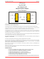
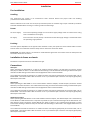
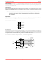
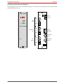
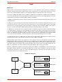
DAC‐4440 Instruction Book
Revision 1
I R T Electronics Pty Ltd A.B.N. 35 000 832 575
26 Hotham Parade, ARTARMON N.S.W. 2064 AUSTRALIA
National: Phone: (02) 9439 3744
Fax: (02) 9439 7439
International:
+61 2 9439 3744
+61 2 9439 7439
Email: sales@irtelectronics.com
Web: www.irtelectronics.com
IRT Eurocard
Type DAC‐4440
AES / 2Mb (E1) G.703
Network Interface Adapter
Designed and manufactured in Australia
IRT can be found on the Internet at:
http://www.irtelectronics.com
www.irtelectronics.com
Page 1 of 14
4440‐DAC_ib_Rev1.doc
DAC‐4440 Instruction Book
Revision 1
IRT Eurocard
Type DAC‐4440
AES / 2Mb (E1) G.703
Network Interface Adapter
Revision History
Revision
0
Date
13/10/2010
By
AL
1
02/06/2011
AL
www.irtelectronics.com
Change Description
Original Issue.
DIP Switch configuration updated to include alarm
settings.
Page 2 of 14
Applicable to:
Firmware version ≥
DAC4440F4V0S4V0
Firmware version ≥
DAC4440F5V0S5V0
4440‐DAC_ib_Rev1.doc
DAC‐4440 Instruction Book
Revision 1
IRT Eurocard
Type DAC‐4440
AES / 2Mb (E1) G.703
Network Interface Adapter
Instruction Book
Table of Contents
Section
Page
Revision History
Operational Safety
General Description
Technical Specifications
Configuration
Link Settings
DIP Switch Settings
Installation
Connections
AES Input
AES Output
AES Reference Input
G.703 (E1) Output
G.703 (E1) Input
Alarm Outputs
RS‐232 Data Port
Front and rear layouts
SNMP – What Is It?
DAC‐4440 SNMP Functions
Maintenance & Storage
Warranty & Service
Equipment return
2
3
4
5
6
6
7
8
8
8
8
8
9
9
9
9
10
11
13
14
14
14
This instruction book applies to units fitted with firmware version ≥ DAC4440F5V0S5V0.
Operational Safety:
WARNING
Operation of electronic equipment involves the use of voltages and currents that
may be dangerous to human life. Note that under certain conditions dangerous
potentials may exist in some circuits when power controls are in the OFF position.
Maintenance personnel should observe all safety regulations.
Do not make any adjustments inside equipment with power ON unless proper
precautions are observed. All internal adjustments should only be made by suitably
qualified personnel. All operational adjustments are available externally without
the need for removing covers or use of extender cards.
www.irtelectronics.com
Page 3 of 14
4440‐DAC_ib_Rev1.doc
DAC‐4440 Instruction Book
Revision 1
IRT Eurocard
Type DAC‐4440
AES / 2Mb (E1) G.703
Network Interface Adapter
General Description
DAC-4440 Block Diagram
DAC-4440
AES
(75Ω or 110Ω)
AES I/P
G.703 O/P
RS232
DAC-4440
AES O/P
E1 O/P
(75Ω)
E1 I/P
(75Ω)
G.703 I/P
DATA I/P
DATA O/P
REFERENCE AES
(75Ω or 110Ω)
AES
(75Ω or 110Ω)
RS232
REF AES I/P
SNMP
SNMP
The DAC‐4440 forms a transmitter/receiver system, which is designed to allow an AES/EBU digital audio signal to
be distributed via a 2Mb G.703 (E1) network.
The DAC‐4440 converts an AES/EBU digital audio signal into a non‐framed 2 Mb G.703 (E1) compatible signal.
The DAC‐4440 combines the 20 bit audio data with either C data, U data or RS232 data into an output stream at
2.048 Mb/s. This stream is then output as a standard G.703 HDB3 encoded 75Ω unframed signal.
The DAC‐4440 also converts a G.703 signal, whose content is formatted as per the output of another DAC‐4440, to
an AES/EBU data stream. The receiver obtains synchronism with the incoming stream and then separates the
audio data from the combined C, U or RS232 data.
The DAC‐4440 allows a local reference AES/EBU signal to be input for rate synchronization of the output. With no
reference signal present, output rate is automatically set to 48 kHz.
The system can handle mono or stereo 20 bit AES/EBU audio at any rate from 25 KHz to 55 kHz, although it is
designed for a nominal 48 kHz.
The system also allows either the Channel (C), User (U) or RS232 data to be conveyed.
Front panel LEDs indicate when an AES/EBU signal and RS232 data is present on the transmit side of the DAC‐
4440, and when a valid 2.048 Mb/s G.703 input signal, and RS232 data, is present and when a valid AES/EBU
reference signal is applied to the receive side of the DAC‐4440.
Relay outputs are provided on the rear assembly for remote status indication for when a valid AES/EBU or E1
signal is present or invalid.
SNMP (Simple Network Management Protocol) remote monitoring is possible when used in conjunction with an
IRT frame fitted with SNMP capability.
Standard features:
•
•
•
•
•
•
Conversion of AES/EBU audio to 2Mb/s G.703 for transport via telecom circuits.
Choice of 75Ω unbalanced or 110Ω balanced AES/EBU line connections.
48 kHz 20 bit default sample rate, 25 – 55 kHz rates supported.
Optional external AES/EBU reference input for rates other than 48 kHz.
Allows Channel (C), User (U) or RS232 data to be conveyed.
Bi‐direction operation possible with independent transmit and receive functions on the one card.
www.irtelectronics.com
Page 4 of 14
4440‐DAC_ib_Rev1.doc
DAC‐4440 Instruction Book
Revision 1
Technical Specifications
IRT Eurocard module
Type DAC‐4440
AES Input:
AES/EBU (75Ω unbalanced or 110Ω balanced).
200 mVp‐p minimum.
AES3‐1992 standard.
25kHz to 55kHz.
>500m 75Ω (Belden 8281).
>200 110Ω (AES digital high quality shielded pair).
Input Level
Format
Sample Rate
Input Cable Length
Data Input:
Type
Rate
RS‐232.
9600 baud.
G.703 Output:
2.048 Mb/s G.703.
75Ω unbalanced terminating.
CCITT G.703 compliant.
Impedance
Format
G.703 Input:
2.048 Mb/s G.703.
75Ω unbalanced terminating.
CCITT G.703 compliant.
Impedance
Format
AES Reference Input:
AES/EBU (75Ω unbalanced or 110Ω balanced).
200 mVp‐p minimum.
AES3‐1992 standard.
25kHz to 55kHz.
>500m 75Ω (Belden 8281).
>200m 110Ω (AES digital high quality shielded pair).
Input Level
Format
Sample Rate
Input Cable Length
AES Output:
AES/EBU (75Ω unbalanced or 110Ω balanced).
AES3‐1992 standard.
Format
Alarms:
MAJOR
MINOR
Settable for either loss of AES or E1. Open circuit on alarm.
Settable for either loss of AES or E1. Open circuit on alarm.
System Performance (End to End):
Dynamic Range
THD + N
Output signal rise and fall times
Frequency Response
Note:
1. Fin =
2. Fout =
120 dB (20Hz to 20kHz, ‐60dB input).
< ‐88 dB (20Hz to 20kHz, full scale input).
(Fin1 & Fout2 between 25 and 55kHz).
< ‐100 dB (1kHz, full scale input ).
(Fin1 & Fout2 between 34 and 55kHz).
< ‐94 dB (10kHz, full scale input).
(Fin1 & Fout2 between 34 and 55kHz).
<20 ns.
±0.05 dB 20Hz to 20kHz.
sample rate of AES/EBU input to DAC‐4440.
sample rate of AES/EBU output from DAC‐4440.
Other:
Power requirement per unit
Temperature range
Connectors Unbalanced
Balanced
Mechanical
Finish:
Front panel
Rear assembly
Dimensions
Accessories supplied with module
28 Vac CT (14‐0‐14) or ± 16 Vdc. (<2 VA).
0 ‐ 50° C ambient.
BNC.
Removable screw terminal blocks.
Suitable for mounting in IRT 19" rack chassis with input output and
power connections on the rear panel.
Grey background, silk‐screened black lettering & red IRT logo.
Detachable silk‐screened PCB with direct mount connectors to Eurocard
and external signals.
30 mm x 3 U x 220 mm IRT Eurocard.
Rear connector.
Due to our policy of continuing development, these specifications are subject to change without notice.
www.irtelectronics.com
Page 5 of 14
4440‐DAC_ib_Rev1.doc
DAC‐4440 Instruction Book
Revision 1
Configuration
Link Settings:
AES Input ‐ Unbalanced 75 Ω:
AES Input ‐ Balanced 110 Ω:
LK2
LK1
LK2
LK1
AES Reference Input ‐ Balanced 110 Ω:
LK4
LK4
LK3
LK3
AES Reference Input ‐ Unbalanced 75 Ω:
AES Output ‐ Balanced 110 Ω:
LK6
LK6
LK5
LK5
AES Output ‐ Unbalanced 75 Ω:
www.irtelectronics.com
Page 6 of 14
4440‐DAC_ib_Rev1.doc
DAC‐4440 Instruction Book
Revision 1
ON
DIP
1 2 3 4 5 6 7 8
SW2
SW1
DIP Switch Settings:
ON
DIP
1 2 3 4 5 6 7 8
SW1‐1 OFF Transmit U data3 (dependent on SW1‐2 setting).
ON Transmit C data4 (dependent on SW1‐2 setting).
SW1‐2 OFF Transmit either C or U data (dependent on SW1‐1 setting).
ON Transmit RS232 data.
SW1‐3
OFF
OFF
OFF
ON
ON
ON
ON
SW1‐4
OFF
ON
ON
ON
ON
OFF
OFF
SW1‐5
X
OFF
ON
ON
OFF
ON
OFF
Alarm Setting
No AES alarm & no E1 alarm.
No AES alarm & E1 as Major (urgent) alarm.
No AES alarm & E1 as Minor (non‐urgent) alarm.
AES as Major (urgent) alarm & E1 as Minor (non‐urgent) alarm.
AES as Minor (non‐urgent) alarm & E1 as Major (urgent) alarm.
AES as Major (urgent) alarm & no E1 alarm.
AES as Minor (non‐urgent) alarm & no E1 alarm.
SW1‐6 OFF DIP switch control.
ON SNMP control.
SW1‐7
Not used.
SW1‐8 OFF Enable major and minor SNMP alarms to the frame Agent (CDM card)5.
ON Disable major and minor SNMP alarms to the frame Agent (CDM card)5.
SW2‐1 to SW2‐8 – Not used.
NOTE: 3
4
5
U data is User application data.
C data is Channel Status Information.
When using TRAPS via SNMP, depending on how system is set up, in order to avoid double reporting
of alarms via the DAC‐4440 card itself and the CDM card (SNMP Agent) of the frame, major and
minor SNMP alarms that are reported to the CDM card of the frame can be disabled.
www.irtelectronics.com
Page 7 of 14
4440‐DAC_ib_Rev1.doc
DAC‐4440 Instruction Book
Revision 1
Installation
Pre‐installation:
Handling:
This equipment may contain or be connected to static sensitive devices and proper static free handling
precautions should be observed.
Where individual circuit cards are stored, they should be placed in antistatic bags. Proper antistatic procedures
should be followed when inserting or removing cards from these bags.
Power:
AC mains supply:
Ensure that operating voltage of unit and local supply voltage match and that correct rating
fuse is installed for local supply.
DC supply:
Ensure that the correct polarity is observed and that DC supply voltage is maintained within
the operating range specified.
Earthing:
The earth path is dependent on the type of frame selected. In every case particular care should be taken to ensure
that the frame is connected to earth for safety reasons. See frame manual for details.
Signal earth: For safety reasons a connection is made between signal earth and chassis earth. No attempt should
be made to break this connection.
Installation in frame or chassis:
See details in separate manual for selected frame type.
Connections:
AES Input:
When operating the DAC‐4440 as an AES to E1 network interface adapter, the AES input (connectors marked
AES I/O) can either be either a 75 Ω unbalanced terminating or 110 Ω balanced terminating as determined by the
links LK1 and LK2 settings as described in the Configuration section of this handbook.
The unbalanced 75 Ω AES connection is via a BNC connector and requires good quality 75 Ω coaxial cable, such as
Belden 8281. The balanced 110 Ω AES connection is via a 3‐pin Phoenix style connector and requires good quality
twisted pair audio cable.
AES Output:
When operating the DAC‐4440 as an E1 to AES network interface adapter, the AES output (connectors marked
AES OUT) can either be either a 75 Ω unbalanced terminating or 110 Ω balanced terminating as determined by the
links LK5 and LK6 settings as described in the Configuration section of this handbook.
The unbalanced 75 Ω AES connection is via a BNC connector and requires good quality 75 Ω coaxial cable, such as
Belden 8281. The balanced 110 Ω AES connection is via a 3‐pin Phoenix style connector and requires good quality
twisted pair audio cable.
AES Reference Input:
When operating the DAC‐4440 as an E1 to AES network interface adapter, the default output rate is automatically
set at 48 kHz. If a different AES rate is required it is possible to input a reference AES signal at the desired rate. The
AES reference input (connectors marked AES IN) can either be either a 75 Ω unbalanced terminating or 110 Ω
balanced terminating as determined by the links LK5 and LK6 settings as described in the Configuration section of
this handbook.
The unbalanced 75 Ω AES connection is via a BNC connector and requires good quality 75 Ω coaxial cable, such as
Belden 8281. The balanced 110 Ω AES connection is via a 3‐pin Phoenix style connector and requires good quality
twisted pair audio cable.
www.irtelectronics.com
Page 8 of 14
4440‐DAC_ib_Rev1.doc
DAC‐4440 Instruction Book
Revision 1
G.703 (E1) Output:
When operating the DAC‐4440 as an AES to E1 network interface adapter, the G.703 (E1) output (connector
marked G.703 OUT) is via a 75 Ω unbalanced terminating BNC connector and requires the use of good quality 75 Ω
coaxial cable, such as Belden 8281.
G.703 (E1) Input:
When operating the DAC‐4440 as an E1 to AES network interface adapter, the G.703 (E1) input (connector marked
G.703 IN) is via a 75 Ω unbalanced terminating BNC connector and requires the use of good quality 75 Ω coaxial
cable, such as Belden 8281.
NOTE: The DAC‐4440 can be used as an AES to E1 network interface adapter (Transmitter) or an E1 to
AES network interface adapter (Receiver) in a uni‐directional link arrangement, or as both an AES
to E1 and E1 to AES network interface adapter at the same time (Transceiver) in a bi‐directional
link arrangement.
Alarm Outputs:
Major and Minor rear assembly alarm outputs are via a 4‐pin phoenix style connector and switch from ground to
open circuit on alarm. See Configuration section of this manual for setting of alarm conditions.
Alarm connections are as follows:
1
Ground.
2
Ground.
3
MAJOR.
4
MINOR.
RS‐232 Data Port:
The RS‐232 data port is via a 10 pin HE14 style of header. Pins 1, 2 and 7 are connected together on the PCB. Pins 9
and 10 are both earthed. Pin 3 is the RS‐232 receive data (RXD) connection. Pin 5 is the RS‐232 transmit data (TXD)
connection. Data rates may be up to 9600 baud. Note that unless the DAC‐4440 is being run in a bi‐directional link
arrangement data transfer is uni‐directional only, i.e. there is no direct data return path.
For connection to a standard RS‐232 9 pin D connector, wire as per the diagram below:
9 Pin D
RS-232
1
CD
2
RXD
RXD
TXD
3
5
7
4
RTS
TXD
6
CTS
8
DTR
RI
GND
9
www.irtelectronics.com
10
Page 9 of 14
1
6
2
7
3
8
4
9
5
Ribbon
Cable
4440‐DAC_ib_Rev1.doc
DAC‐4440 Instruction Book
Revision 1
Front & rear panel connector diagrams
The following front panel and rear assembly drawings are not to scale and are intended to show connection order
and approximate layout only.
D AC-44 40
PL7
PL10
1-GND
2-GND
3–MAJOR
4-MINOR
1
SK 1
3
4
75Ω
AES IN
DATA
AES
Input
or
3
110Ω
G.703
Alarm
Output
2
2
1
SK 2
AES I/O
DATA AES REF.
PL8
75Ω
Reference
AES
RS232
Data Port
or
3
110Ω
2
SK 7
RS232/RS485
1
G.703 (E1)
Input
SK 3
AES IN
G.703 IN
DC
AES
Output
SK 8
75Ω
G.703 (E1)
Output
or
3
110Ω
G.703 OUT
2
AES OUT
PL9
1
N140
www.irtelectronics.com
Page 10 of 14
4440‐DAC_ib_Rev1.doc
DAC‐4440 Instruction Book
Revision 1
SNMP
What Is It?
SNMP stands for Simple Network Management Protocol. It is an application layer protocol for managing IP
(Internet Protocol) based systems. SNMP enables system administrators to manage system performance, and to
find and solve system problems. SNMP runs over UDP (User Datagram Protocol), which in turn runs over IP.
Three types of SNMP exist: SNMP version 1 (SNMPv1), SNMP version 2 (SNMPv2) and SNMP version 3 (SNMPv3).
It is not the intention here to discuss the differences between various versions, only to bring attention to the fact
that IRT Electronics modules, fitted with SNMP capability, use SNMPv1.
An SNMP managed network consists of three key components: Network Management Systems (NMS), agents, and
managed devices.
An NMS is the console through which the network administrator performs network management functions, such
as monitoring status (e.g. alarm states) and remote controlling, of a set of managed devices. One or more NMSs
must exist on any managed network. Generally the NMS is a computer running third party SNMP control software.
There are a number of third party SNMP software applications currently available on the market.
An NMS polls, or communicates with, an agent. An agent is a network management software module that resides
in a managed device. An agent has local knowledge of management information and translates that information
into a form compatible with SNMP. The agent, therefore, acts as an interface between the NMS and the managed
devices. The NMS sends a request message, and control commands for the managed devices, to the agent, which
in turn sends a response message, containing information about the managed devices, back to the NMS.
A managed device contains an SNMP agent and resides on a managed network. Managed devices collect and store
management information and make this information available to NMSs using SNMP.
Managed device agent variables are organised in a tree structure known as a Management Information Base
(MIB). Within the MIB are parameters pertaining to the managed device. An Object Identifier (OID) number within
the MIB defines the managed device type. This is a unique number specific to the model of managed device. Other
information relating to the device is also stored, information such as alarm states, controllable settings, etc. The
MIB tree is organised in such a way that there will be no two MIB files with conflicting placements.
Normally an NMS polls an agent for information relating to the MIB in a managed device to be sent back to the
NMS. When certain conditions are met within the MIB, such as major alarm conditions, for example, the agent
automatically sends what is known as a trap to the NMS without any prompting from the NMS. This allows
automatic notification of a predetermined event.
SNMP Block Diagram
NMS
IP
Network
NMS
www.irtelectronics.com
Page 11 of 14
SNMP Agent
Protocol Engine
MIB
SNMP Agent
SNMP Agent
Protocol Engine
MIB
SNMP Agent
SNMP Agent
Protocol Engine
MIB
SNMP Agent
4440‐DAC_ib_Rev1.doc
DAC‐4440 Instruction Book
Revision 1
SNMP with IRT Products:
IRT Electronics currently employs SNMPv1 with its SNMP capable frames. The frame acts as an agent when fitted
with a CDM‐xxxx module. This module has its own designated slot next to the power supply so as to not affect the
number of modules that the frame will take. Communication between the NMS, the frame and its loaded modules
are via this CDM‐xxxx module. Note that the NMS software is third party and not supplied by IRT Electronics.
Ethernet connection for SNMP operation is via an RJ45 connector on the rear of the frame, below the mains inlet.
Ethernet rate runs at either 10 baseT or 100 baseT.
Frame parameters, such as Name, Address and Location, are set via an RS232 interface, a D9 connector on the
rear of the frame below the mains inlet. A software terminal emulator, such as Tera Term or HyperTerminal, is
used for setting and reading the parameters of the frame.
IRT modules that are SNMP compatible need a plug‐in SMU‐4000 module with a program relevant to the module
that it is plugged into. Depending on the module, besides the module identification, parameters such as alarm
states, inputs and controls etc. are communicated to the CDM‐xxxx agent via a data bus on the rear of the frame.
Thus the CDM‐xxxx collects information on what is loaded within the frame, what positions they occupy, and their
current status for communication to the NMS when the NMS sends a request for information.
In the event of a major alarm from any of the SNMP compatible modules, or power supplies, a trap is
automatically sent by the CDM‐xxxx agent to the NMS without any prompting by the NMS. This alerts the operator
to any fault conditions that may exist that need immediate attention.
110/240 V 50/60 Hz
0.7 A (max.)
FRU-4000
FRAME
FUSES
220/240 Vac
500 mA S.B.
110/120 Vac
1A S.B.
RS232
Alarm
Ethernet
+
48Vdc
AS3260 approval no.: CS6346N
Ass. no.: 804692
IRT SNMP Connections
IRT modules fitted
with SMU-4000
NMS
IP
Ethernet Cable
Network
CDM-xxxx
PSU’s
IRT SNMP Frame
Ethernet Cable
IRT modules fitted
with SMU-4000
CDM-xxxx
PSU’s
IRT SNMP Frame
Ethernet Cable
IRT SNMP Setup
www.irtelectronics.com
Page 12 of 14
4440‐DAC_ib_Rev1.doc
DAC‐4440 Instruction Book
Revision 1
DAC‐4440 SNMP Functions:
With the DAC‐4440 installed in an IRT 4000 series frame with SNMP capability, the DAC‐4440 can be configured
and interrogated by an SNMP Network Management System (NMS).
The following SNMP functions are capable of being configured and monitored by an NMS:
aesInput
‐ An indication that the AES input signal is present.
[notPresent (1), present (2)];
aes48K
‐ An indication if the AES input signal is at 48kHz frame rate.
[notPresent (1), present (2)];
controlSource
‐ An indication that auxiliary data is controlled by DIP switch or via SNMP.
[dipSwitch (1), remoteSNMP (2)];
NOTE: DIP switch SW1‐6 on DAC‐4440 controls this setting.
auxSource
‐ An indication and control of the auxiliary data that is packed in the G.703 (E1).
[userData (1), channelStatus (2), rs232 (3);
NOTE: If DIP switch SW1‐6 is OFF, DIP switches SW1‐1 and SW1‐2 on DAC‐4440 controls
these settings.
eOne
‐ An indication that the G.703 (E1) input is present.
[notPresent (1), present (2)];
aesRef
‐ An indication that the AES reference input signal is present.
[notPresent (1), present (2)];
auxData
‐ An indication of the auxiliary data that is received from the input G.703 (E1).
[userData (1), channelStatus (2), rs232 (3);
irt4440fpgaVersion
‐ An indication of the firmware version of the main FPGA in the format x.y where x is the
major revision number and y is the minor revision number;
irt4440SoftwareVersion
‐ An indication of the software version of the NIOS in the format x.z where x is the major
revision number and z is the minor revision number;
irt4440reset
‐ A set with a value of 2 sent to this OID will cause a system reset to occur. When queried
returns null.
irt4440presAESTrapEnable ‐
irt4440presE1TrapEnable
www.irtelectronics.com
If enabled, traps will be sent when an AES input is present and when it is not present.
[notEnabled (1), enabled (2)];
‐ If enabled, traps will be sent when a G.703 (E1) input is present and when it is not
present.
[notEnabled (1), enabled (2)].
Page 13 of 14
4440‐DAC_ib_Rev1.doc
DAC‐4440 Instruction Book
Revision 1
Maintenance & Storage
Maintenance:
No regular maintenance is required.
Care however should be taken to ensure that all connectors are kept clean and free from contamination of any
kind. This is especially important in fibre optic equipment where cleanliness of optical connections is critical to
performance.
Storage:
If the equipment is not to be used for an extended period, it is recommended the whole unit be placed in a sealed
plastic bag to prevent dust contamination. In areas of high humidity a suitably sized bag of silica gel should be
included to deter corrosion.
Where individual circuit cards are stored, they should be placed in antistatic bags. Proper antistatic procedures
should be followed when inserting or removing cards from these bags.
Warranty & Service
Equipment is covered by a limited warranty period of three years from date of first delivery unless contrary
conditions apply under a particular contract of supply. For situations when “No Fault Found” for repairs, a
minimum charge of 1 hour’s labour, at IRT’s current labour charge rate, will apply, whether the equipment is
within the warranty period or not.
Equipment warranty is limited to faults attributable to defects in original design or manufacture. Warranty on
components shall be extended by IRT only to the extent obtainable from the component supplier.
Equipment return:
Before arranging service, ensure that the fault is in the unit to be serviced and not in associated equipment. If
possible, confirm this by substitution.
Before returning equipment contact should be made with IRT or your local agent to determine whether the
equipment can be serviced in the field or should be returned for repair.
The equipment should be properly packed for return observing antistatic procedures.
The following information should accompany the unit to be returned:
1.
2.
3.
4.
5.
6.
7.
A fault report should be included indicating the nature of the fault
The operating conditions under which the fault initially occurred.
Any additional information, which may be of assistance in fault location and remedy.
A contact name and telephone and fax numbers.
Details of payment method for items not covered by warranty.
Full return address.
For situations when “No Fault Found” for repairs, a minimum charge of 1 hour’s labour will apply,
whether the equipment is within the warranty period or not. Contact IRT for current hourly rate.
Please note that all freight charges are the responsibility of the customer.
The equipment should be returned to the agent who originally supplied the equipment or, where this is not
possible, to IRT direct as follows.
Equipment Service
IRT Electronics Pty Ltd
26 Hotham Parade
ARTARMON
N.S.W. 2064
AUSTRALIA
Phone:
Email:
www.irtelectronics.com
61 2 9439 3744
service@irtelectronics.com
Page 14 of 14
Fax:
61 2 9439 7439
4440‐DAC_ib_Rev1.doc