1
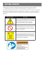
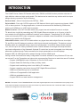
HVWIP-Series (HVWIP-T + HVWIP-R) Installation Manual HDMI LAN Video Wall Matrix Extender 1 TABLE OF CONTENTS Contents Chapter 1: GETTING STARTED.........................................................................................................1 1.1 IMPORTANT SAFEGUARDS............................................................................................................. 1 1.2 SAFETY INSTRUCTIONS................................................................................................................. 1 1.3 REGULATORY NOTICES FEDERAL COMMUNICATIONS COMMISSION (FCC)........................... 2 Chapter 2: INTRODUCTION................................................................................................................3 2.1 PACKAGE CONTENTS..................................................................................................................... 4 2.2 BEFORE INSTALLATION................................................................................................................... 4 2.3 APPLICATION DIAGRAM.................................................................................................................. 5 2.4 PANEL DESCRIPTION...................................................................................................................... 8 2.4.1 INPUT PANEL (Transmitter, HVWIP-T) FRONT ...................................................................... 8 2.4.2 INPUT PANEL (Transmitter, HVWIP-T) REAR ......................................................................... 8 2.4.3 INPUT PANEL (Receiver, HVWIP-R) FRONT .......................................................................... 9 2.4.4 INPUT PANEL (Receiver, HVWIP-R) REAR............................................................................. 9 Chapter 3: INSTALLATION (HVWIP-SERIES)..............................................................................10 3.1 INSTALLATION OF CONTROL SOFTWARE..................................................................................... 10 3.1.1 CONTROL SOFTWARE ........................................................................................................... 10 CONTROL SOFTWARE DEVICES........................................................................................... 11 Chapter 4: SETTING DEVICE PARAMETERS..............................................................................13 MODIFY DEVICE SETTINGS........................................................................................14 Chapter 5: DEVICE SETTING WINDOW GUIDE..........................................................................15 Chapter 6: MATRIX SETTINGS..........................................................................................................16 CREATE SCENE WINDOW...........................................................................................17 SCENE AREA WINDOW................................................................................................17 Chapter 7: VIDEOWALL SETUP.......................................................................................................19 Chapter 8: RS232 REMOTE CONTROL.........................................................................................22 Chapter 9: CONFIGURATION FILE MANAGEMENT.................................................................23 Chapter 10: LOGS ................................................................................................................................24 Chapter 11: SPECIFICATIONS..........................................................................................................25 GETTING STARTED 1.1 IMPORTANT SAFEGUARDS Please read all of these instructions carefully before you use the device. Save this manual for future reference. What the warranty does not cover • Any product, on which the serial number has been defaced, modified or removed. • Damage, deterioration or malfunction resulting from: • Accident, misuse, neglect, fire, water, lightning, or other acts of nature, unauthorized product modification, or failure to follow instructions supplied with the product. • Repair or attempted repair by anyone not authorized by us. • Any damage of the product due to shipment. • Removal or installation of the product. • External causes to the product, such as electric power fluctuation or failure. • Use of supplies or parts not meeting our specifications. • Normal wear and tear. • Any other causes which does not relate to a product defect. • Removal, installation, and set-up service charges. 1.2 SAFETY INSTRUCTIONS The HVWIP-Series, Videowall Matrix IP POE Extender with Audio, RS232 and KVM function has been tested for conformance to safety regulations and requirements, and has been certified for international use. However, like all electronic equipments, the HVWIP-Series should be used with care. Read the following safety instructions to protect yourself from possible injury and to minimize the risk of damage to the unit. Do not dismantle the housing or modify the module. Dismantling the housing or modifying the module may result in electrical shock or burn. Refer all servicing to qualified service personnel. Do not attempt to service this product yourself as opening or removing housing may expose you to dangerous voltage or other hazards Keep the module away from liquids. Spillage into the housing may result in fire, electrical shock, or equipment damage. If an object or liquid falls or spills on to the housing, unplug the module immediately. Have the module checked by a qualified service engineer before using it again. Do not use liquid or aerosol cleaners to clean this unit. Always unplug the power to the device before cleaning. 1 GETTING STARTED 1.3 Regulatory Notices Federal Communications Commission (FCC) This equipment has been tested and found to comply with Part 15 of the FCC rules. These limits are designed to provide reasonable protection against harmful interference in a residential installation. Any changes or modifications made to this equipment may void the user’s authority to operate this equipment. Warning symbo Description ONLY USE THE PROVIDED POWER CABLE OR POWER ADAPTER SUPPLIED. DO NOT TAMPER WITH THE ELECTRICAL PARTS. THIS MAY RESULT IN ELECTRICAL SHOCK OR BURN. DO NOT TAMPER WITH THE UNIT. DOING SO WILL VOID THE WARRANTY AND CONTINUED USE OF THE PRODUCT. THE VIDEO BOARDS ARE VERY SENSITIVE TO STATIC. PLEASE ENSURE IF RACK MOUNTED OR INSTALLED ON A SURFACE, IT SHOULD BE IN A GROUNDED ENVIROMENT. 2 INTRODUCTION The HVWIP-Series, Matrix IP Extender with Audio, RS232 and KVM function provides extension of high definition video and high quality audio. This device can be used into any solution with its unique design allowing connection by the following: Point to Point - (Direct Connection with CAT5/6) - 330ft Point to Multi - Point with CAT5/6 requires a POE Network Switch which supports port based, IGMP v2.0 or above protocol. For large application, we would recommend Dell Networking 5500 series, which use 2 HDMI port or 2 SFP port to cascade. Matrix Function - with CAT 5/6 cable without any signal loss add multiple Sources to multiple TX which links via LAN by cascading any POE Gigabit Ethernet switches up to 3 levels, to the Rx connected to the HD Monitors at different locations on the Network. Transporting Full HD 1080p video and internally JPEG video compression adapts to available network bandwidth if needed while retaining vivid picture with PCM audio. Videowall Function - with CAT 5/6 cable without any signal loss add multiple Sources to multiple TX and RX to the HD displays to achieve a Multi Input videowall configuration. The device ensures flexibility within any videowall design, layout and configuration. Its modular design allows example 1x2 ,2x2 3x3 up to 4x3. Easily controlled via the Control Software to manage and setup the bezel, input and configuration of the Videowall. Optional IP control box to send commands via a third party automation system through Telnet commands for simple presentation on the HD diplays. Support USB 2.0, USB signal will be passed through with the HDMI signal Having a small form factor and easily configurable via control software on any Windows PC the user can set an IP on the Transmitter and choose the corresponding Receiver to match the same IP subnet. • Support 1080P@60Hz up to 100meters in Point-to-Point mode. • Support Seamless Switching in Many-to-Many mode. • Support matrix switching control over LAN by PC software. • Support cascading connection through POE Gigabit Ethernet Switch. • HDMI local Pass-through out in transmitter. • USB over IP supported for KVM application. • HDMI de-embedded audio out. • Support RS232 and web interface management. NOTES: The QUALITY and TRANSMISSION of the video signals depends on the characteristics and quality of the UTP cables and Network Infrastructure. We recommend any Network Switches with 10GB POE IGMP v2.0 support. Tested and configured on the below models. 3 INTRODUCTION 2.1 PACKAGE CONTENTS Before you start the installation of HIP-S, please check the A. STANDARD package contents. 1 HVWIP-Series X 1 2 POWER BRICK (+12V DC 2A) + POWER CORD X1 3 AVAILABLE ON REQUEST FOR INTERNATIONA POWER HVWIP-Series (HVWIP-T + HVWIP-R) 4 USER’S MANUAL X 1 Installation Manual HDMI LAN Video Wall Matrix Extender 1 2.2 BEFORE INSTALLATION • Put the product in a level and stable location. If the product falls, it may cause damage or malfunction to components within the casing. • Do not place the product in temperatures under 0˚C or over 50˚C. High humidity may also cause the unit to malfunction. • Use the DC power adapter with correct specifications supplied with the unit. If the improper power supply is used, this may result in malfunction of the unit and may cause fire. • Do not twist or pull by force the ends of the UTP cable. It will cause malfunction. 4 INTRODUCTION 2.3 APPLICATION DIAGRAM POINT TO POINT KVM FUNCTION 1080p = 100m (330 feet) CAT5 CABLE INDEX 1080p = 100m (330 feet) CAT6 INPUT / OUTPUT AUDIO CAT-5 / CAT-6 USB RS232 LOCAL OUTPUT USB HDMI SOURCE HVWIP-T RS-232 CONTROL AUDIO 100M (330FT) HVWIP-R REMOTE KEYBOARD MOUSE 5 INTRODUCTION IP LAN MATRIX FUNCTION FULL HD1080P (1920X1080) = 100m (330 feet) CAT5/6 WUXGA(1920X1200) = 100m (330 feet) CAT5/6 CABLE INDEX OUTPUT INPUT / SOURCE HDMI Source 1 HDMI Source 2 HDMI Source 3 LOCAL OUTPUT LOCAL OUTPUT HVWIP-T Transmitters can be up to 100m (330ft) from the Network Switch CONTROL SOFTWARE CONFIGURATION GIGABIT SWITCH with IGMP v2.0 HVWIP-R Receivers can be up to 100m (330ft) to HD Display HDMI Source 1 HDMI Source 2 HDMI Source 3 HDMI Source 3 HDMI Source 3 HDMI Source 1 HDMI Source 1 HDMI Source 2 6 INTRODUCTION VIDEOWALL APPLICATION CABLE INDEX INPUT / OUTPUT CAT5E / 6 LAYER 1 HDTV 1 HDTV 2 HDTV 3 LAYER 2 HDTV 4 HDTV 5 HDTV 6 LAYER 3 HDTV 7 HDTV 8 HDTV 9 LAYER 4 HDTV 10 HDTV 11 HDTV 12 GIGABIT SWITCH HVWIP-T HDMI Source 3 HDMI Source 2 HVWIP-T HVWIP-T HDMI Source 1 Web GUI Control PC or Ipad 7 INTRODUCTION 2.4 PANEL DESCRIPTION 2.4.1 INPUT PANEL (Transmitter, HVWIP-T) Front 1 1 2 3 Operation Mode: Normal Mode: Transmit Rs232 signal between Tx/Rx Debug Mode: Use for Debug device 2 Power LED: Indicates Power active. 3 Link LED: Connection is made to the Rx at the HD Monitor 2.4.2 INPUT PANEL (Transmitter, HVWIP-T) Rear 4 5 6 4 Power Connector: 12V DC Power Supply 7 8 9 5 USB Port: Type B female USB connection for PC KVM support. 6 Ethernet Jack: HDMI signal and control data out to RX 7 HDMI IN: HDMI Female 19 Pin port for source device 8 HDMI OUT: HDMI Female 19 Pin port for local out HDMI Monitor 9 RS-232 Jack : 3 pin Terminal Block Connector for serial control 8 INTRODUCTION 2.4.3 Input Panel (Receiver, HVWIP-R) Front 1 1 2 3 4 5 Operation Mode: Normal Mode: Transmit Rs232 signal between Tx/Rx Debug Mode: Use for Debug device 2 Power LED: Indicates Power active. 3 Link LED: Connection is made to the Rx at the HD Monitor 4 USB Port: Type A female USB 2.0 for connecting peripheral devices 5 USB Port: Type A female USB 2.0 for connecting peripheral devices 2.4.4 INPUT PANEL (Receiver, HVWIP-R) Rear 6 7 8 9 10 11 12 6 Power Connector: 12V DC Power Supply 7 USB Port: Type A female USB 2.0 for connecting peripheral devices. 8 USB Port: Type A female USB 2.0 for connecting peripheral devices 9 Ethernet Jack: HDMI signal and control data IN form TX 10 RS-232 Jack : 3 pin Terminal Block Connector for serial control 11 Audio Jack : 3 pin Terminal Block Connector for 5.1 PCM audio out to speakers 12 HDMI OUT: HDMI Femaile 19 Pin port for local out HDMI Monitor 9 INSTALLATION (HVWIP-SERIES) To setup HVWIP-Series please follow these steps for connecting to a device: 1. Turn off all devices including monitors / TV 2. Connect a HDMI source (such as a Blu-Ray Disc player or PC) to the Transmitter HVWIP-T 3. Connect USB cable to the PC (only if PC is the source and your extending KVM function) 4. Connect CAT5/6 from TX to RX CAT5/6 port HVWIP-R 330 feet away 5. Connect Combo USB Keyboard and Mouse Wireless dongle to control PC at Display end 330 feet away. 6. Ensure all cable connections are secure and not loose 7. Plug in 12V DC Power (supplied). 8. Power on HDMI Source 9. Power on the HDMI display 3.1 INSTALLATION OF CONTROL SOFTWARE 3.1.1 Control Software The HVWIP-Series can be controlled via Windows based Laptop/PC by installing the software VWIP ControlPro.exe GENERAL INSTRUCTIONS • Before you begin the installation of the control software ensure the both the HVWIP-Series is connected to AC power. • PC Requirements-Windows® XP/Windows Vista®/Windows® 7/Windows® 8 • Ensure the Laptop/PC is plugged in to AC power during the installation process. It is not recommended to use only battery power during the installation. Do not remove power at any time during the installation process as this could lead to incomplete results. SOFTWARE INSTALLATION • Insert the Installation Disc provided Optional or the Control software can be downloaded from the AG Neovo website. • After installation launch the Control software VWIPControlPro.exe NOTES: If you run the ControlPro tool for the first time on Windows Vista or a later version OS, the Windows Security Alert dialog box is displayed after an attempt to search devices. 10 INSTALLATION (HVWIP-SERIES) In this case, select both check boxes in the dialog box and click Allow access to resolve this issue. If the search has timed out or failed, re-perform the search. The Rx and Tx devices are assigned IP addresses in the Auto IP mode by default. The network segment for their IP addresses is 169.254.x.x and the subnet mask is 255.255.0.0. If no device is searched, check the computers IP address where the HDMI over IP tool is installed and if it resides within the same network segment as the Rx and Tx devices, and whether the computer shares the subnet mask 255.255.0.0. CONTROL SOFTWARE DEVICES GUI ELEMENT DESCRIPTION IMPORT Allows the user to Import past saved FILE settings and layouts for easy setup and Multiple same projects which require the same configuration. EXPORT The user can easily Export the current FILE settings and layouts for easy recall and future setup. SERIAL This enables the RS232 control POP up window and RS232 control function. The USER can simply control the Source device or Monitor from the RS232 Library listed within the Control Software from any PC. INFORMATION This enables the Device Info Window to notify the USER Device Name:/Device Type/IP address. LOG This enables the Device Log Window to notify the USER date and time the unit was searched and what function the unit is set to Single cast or Multicast. HELP Information on the Control Software Version. 11 INSTALLATION (HVWIP-SERIES) SEARCHING DEVICES STEP 1: Click search as shown below in DEVICE LIST SECTION STEP 2: All functions are disabled when in search is in progress STEP 3: When search is completed the discovered devices are displayed in the device list window. The devices will show active “Green Circles”. NOTES: If the Rx and Tx devices have been configured before by this software tool, Check the Restore matrix after search box.This would proceed to search the devices and set the previous matrix configurations automatically after the restore search. 12 SETTING DEVICE PARAMETERS To change or set the device parameters right-click on any device as shown below: OPERATION DESCRIPTION CONFIG User can configure the device parameters. Such as device name and IP preference(AUTO DHCP STATIC). UPDATE Update any changes made with-in the Config. DELETE Deletes the devices that have been searched and is listed below in the devices column. TURN ON OSD Displays ON Screen Display- Info This operation is valid only when a single device is selected. TURN OFF OSD Disables the On Screen Display Info This operation is valid only when a single device is selected. Restores the factory settings for devices. This operation is valid when one or more devices are selected. When this operation is executed, restart the devices RESET DEFAULT for the factory settings to take effect, delete devices displayed in the device list, and search the units again. RESTART Restarts the devices. 13 SETTING DEVICE PARAMETERS MODIFY DEVICE SETTINGS When you right- click a device in the Device List and choose Modify the device setting dialog box is displayed. 14 DEVICE SETTING WINDOW GUIDE GUI ELEMENT ATTRIBUTE DESCRIPTION DEVICES Indicates the current device on which you perform operations. HOST NAME ID Indicates the host name ID, which is generated by the system and cannot be changed. NAME PARAMETER Indicates the user-defined device name that contains a maximum of 80 characters. IP ADDRESS Indicates the device IP address, which can be set only when the static mode is selected. NETMASK Indicates the subnet mask for the device, which can be set only when the static mode is selected. AUTO IP indicates a mode in which the device is assigned an IP address automatically. DHCP OPTION Indicates a mode in which the device is assigned an IP address by using a router or switch. STATIC indicates a mode in which the IP address is assigned manually. OK Saves current settings, applies them to the device, and closes the Device settings dialog box. CANCEL BUTTON APPLY Cancels current settings and closes the Device settings dialog box. Saves current settings and applies them to the device without closing the Device settings dialog box. NOTES: If any changes are made within the window –Example IP Address Settings change to Static, Auto IP or DHCP. STEP1: Power cycle the device STEP2: Search the device again within the Control Software 15 MATRIX SETTINGS In the main GUI of the HDMI over IP tool, the Matrix area displays all the GUI elements related to device connections. GUI ELEMENT ATTRIBUTE DESCRIPTION Creates a New Configuration. Modifies the current Configuration. BUTTON Deletes the current Configuration. Applies the Configuration connection settings to the connected devices. OPTION Specifies that settings are applied immediately after you double-click the intersection between a row and column in the lower part. Indicates the status of the matrix. Indicates that the matrix created by devices is restored. PARAMETER Indicates that the matrix settings are in progress. Indicates that matrix settings are applies successfully. Indicates that matrix settings fail to be applied. 16 MATRIX SETTINGS CREATE SCENE WINDOW After your click in the SCENE area, the Create dialog box is displayed The user can change the configuration layout. Modify Scene – The user can edit the Name or Change the Layout SCENE AREA WINDOW You can also right click to perform other operations in the Scene dialog box. 17 MATRIX SETTINGS OPERATION DESCRIPTION CHANGE TX User can select which TX (source to be displayed) from the search devices on each Monitor- Matrix /Videowall Function . CHANGE RX User can select which RX (Monitor) to be configured Matrix/Videowall Function. REMOVE TX Deletes the TX source from the search devices below in the devices column. REMOVE RX Deletes the RX Monitor from the search devices below in the devices column. SELECT ALL This selects all the Cells in the Scene window dialog box.To perform quick and easy split function (1) one TX to all Monitors. COMBINE After all is selected this function combine al the cells to enable the Videowall Mode. SPLIT This function cancels the combine function to re-enable the Matrix Mode and have each monitor single. The user can easily choose what SOURCE or MONITOR by simply choosing: Change TX or Change RX as shown below: 18 VIDEOWALL SETUP The user can Right-Click in the scene area to open the user configurable options: STEP 1: Choose Select All STEP 2: When all the cells are selected right click and choose combine After the second step is completed Videowall Properties window pops up. 19 VIDEOWALL SETUP STEP 3: Create a Name for the Videowall STEP4: Insert the measurements of the Display Bezel Width and Height NOTE: (All Monitors Must be the Same) OW – Outside width of Monitor/TV in mm OH – Outside height of Monitor/TV in mm VW- Inside width of Monitor/TV in mm VH- Inside width of Monitor/TV in mm STEP 4: Choose which source configuration you would like to setup Single Host Mode: Assign the same video-source to all cells. Multi Host Mode: Allows different cell/rows could be assigned with different video sources Advance Settings Allows the user to precisely adjust the video on each Monitor to perform the correct configuration and outcome for any project. 20 VIDEOWALL SETUP STEP 5: The user can identify the Videowall is created in the Control Software by the double green lines combining all the TVs the user have created in the SCENE settings Example 3x3 STEP 6: The user can easily right click on the Videowall created and choose Change TX, this will allow simple switching of any of the searched TX in the listed devices to be displayed across the Videowall. 21 RS232 REMOTE CONTROL Controller (Commands sent via Control box) Commands Commands TX RX Through RS232 port Through RS232 port From control box to transmitter and receiver (JPEG2000/H.264) TX Bi-directional RS232 Through RS232 port RX Through RS232 port Bi-directional RS232 channel (JPEG2000) 22 CONFIGURATION FILE MANAGEMENT Default file: when the configuration tool is closed, the Windows OS would save the configuration file default.hoi to the working directory of current user: Windows XP by C:\Documents and Settings\#user#\Local Settings\Application Data\ControlPro; Windows Vista or later OS version by C:\Users\#user#\AppData\Local\ControlPro, #user# is current user name of operation system). When start the tool next time, it would automatically read the configuration file default.hoi. Do not modify or delete the default. hoi. Otherwise, errors may be encountered during program running. 1: Save current devices and scene configuration information to specified directory. 2: Import configuration file to specified directory. NOTES: The variable #user# indicates the user name for the OS. In addition, you can click Export to save the configuration file to a specified directory, and click Import to import the configuration file from this directory. 23 LOGS The logs have recorded the tool operation and device communication information. They can be used by technical engineers for troubleshooting. 24 SPECIFICATIONS ITEM UNITS UNIT DESCRIPTION DESCRIPTION HVWIP-T HVWIP-R HDMI Transmitter HDMI COMPLIANCE HDMI Receiver Full HD HDCP COMPLIANCE Yes with Key Code VIDEO BANDWIDTH Single Link 225 MHz (6.75Gbps) SUPPORTED RESOLUTIONS DTV/HDTV; 1080P/1080i/720P/576P/480P/576i/480i RESOLUTION AND DISTANCE @ 8-BIT Full HD: (1080p) ~ 100meter (330feet) (CAT5/6/7) AUDIO SUPPORT Stereo and Digital Audio RS232 SUPPORT Pass Through ONLY within Control Software INPUT TMDS SIGNAL 0.5-1.0 Volts (peak-to-peak) INPUT DDC SIGNAL 5 Volts (peak-to-peak, TTL) ESD PROTECTION - Human body model — ±19kV (air-gap discharge) & ±12kV (contact discharge) - Core chipset — ±8kV INPUT OUTPUT 1 x RJ45 1x USB TYPE B 1 x HDMI 1X 3.5mm 1x 3PIN 1 x RJ45 4x USB TYPE B 1 x HDMI 1 x HDMI 1X 3.5mm 2 x 3PIN HDMI CONNECTOR Type A (19 pin female) RJ45 CONNECTOR WE/SS 8P8C with 2 LED indicators DIMENSIONS (L X W X H) 5.16’’W×4.53’’H×0.98’’D POWER SUPPLY 12V DC POWER CONSUMPTION 5 Watt (max) Environmental OPERATING TEMPERATURE 32˚ ~ 104˚F (0˚ to 40˚C) STORAGE TEMPERATURE -4˚ ~ 140˚F (-20˚ ~ 60˚C) RELATIVE HUMIDITY 20~90% RH (no condensation) 25 SPECIFICATIONS 1. All HDMI over CATx transmission distances are measured using Belden CAT6A (625MHz), 4-Pair,UTP-Unshielded, Riser-CMR, Premise Horizontal Cable, 23 AWG Solid Bare Copper Conductors, Polyolefin Insulation, Patented Double-H spline, Ripcord, PVC Jacket using Quantum 980 signal HDMI Video Generator Module with Video Pattern Testing and shielded ends. 2. The transmission length is largely affected by the type of category cables, also the type of HDMI sources, and the type of HDMI display. The testing result shows solid UTP cables (usually in the form of 300m or 1000ft bulk cable) can transmit a lot longer signals than stranded UTP cables (usually in the form of patch cords). Shielded STP connectors are better suit than unshielded UTP connectors. A solid UTP CAT6A cable shows longer transmission length than solid UTP CAT5E/6E cable. 3. EIA/TIA-568-B termination (T568B) for category cables is recommended. 4. To reduce the interference among the unshielded twisted pairs of wires in category cable, you can use shielded STP cables with shielded connector to improve EMI problems, which occurs in poor wiring environments with unplanned cable runs situated away from EMI interference. 5. Because the quality of the category cables has the major effects in how long transmission distance will be made and how good is the received signal on the display, the actual transmission length is subject to high quality category cables. For resolution greater than 1080i or 1280x1024, a solid CAT6E 250MHz cable is the only viable choice. PERFORMANCE GUIDE FOR HDMI OVER CATEGORY CABLE TRANSMISSION PERFORMANCE RATING WIRING SOLID STRANDED TYPE OF CATEGORY CABLE SHIELDING CAT5 CAT5E CAT6 UNSHIELDED (UTP) SHIELDED (STP) UNSHIELDED (UTP) SHIELDED (STP) TERMINATION PLEASE USE EIA/TIA-568-B TERMINATION (T568B) AT ANY TIME Service Contact: service.nl@agneovo.com 26