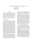
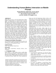
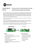
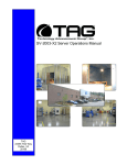
1
SV-101-THS “BRICK” Operations Manual
TAG
22355 TAG Way
Dulles, VA 20166
Operations Manual
1 Copyright © 2009 Technology Advancement Group®, Inc.
(TAG®)
All rights reserved. This publication and its contents are proprietary to TAG. No part of
this publication may be reproduced in any form or by any means without the written
permission of TAG, 22355 TAG Way, Dulles, Virginia 20166-9310.
TAG has made every effort to ensure the correctness and completeness of the material
in this document. TAG shall not be liable for errors contained herein. The information in
this document is subject to change without notice. TAG makes no warranty of any kind
with regard to this material, including, but not limited to, the implied warranties of
merchantability and fitness for a particular purpose.
1.1
Trademarks
All trademarks, marks, names, or product names referenced in this publication are the
property of respective owners, and TAG neither endorses nor otherwise sponsors any
such products or services referred to herein.
SV-101-THS
Part Number:
Page 2 of 63
Version 1.0. 07/09/2008
Operrations Man
nual
2 Ab
bout TAG
G
2.1
Summary of Qualific
cations
TAG hass served as
s a leading provider off IT solution
ns to DoD customers
c
o
over
the passt
20+ yea
ars and has a long-stan
nding and respected
r
h
history
of prroviding Systems
Enginee
ering, Electrronic Equip
pment and Program
P
Ma
anagementt support to
o US Militaryy
warfighters. Headq
quartered in
n Dulles, Viirginia, TAG
G’s state-off-the-art 35,,000 sq. ft.
ng facility prrovides all the
t infrastru
ucture, equipment, and
engineering and manufacturin
wer necessa
ary to engin
neer, design
n, test, man
nufacture, and
a certify products
p
to
o the
manpow
rugged requiremen
r
nts of the ta
actical comb
bat theater. Our facilitties in Dulle
es, VA, San
n
Diego, CA,
C and St. Louis, MO
O, allow for rapid
r
deployment of prroducts and
d support
across the globe.
ently, and cost-effectiv
c
vely tailors rugged
r
solu
utions for la
arge DoD
TAG quiickly, efficie
program
ms with spec
cific MIL-ST
TD requirem
ments. TAG
G’s compre
ehensive Qu
uality
Assuran
nce (QA) po
olicy – enforced throug
gh application of our UL-registere
U
ed ISO
9001:20
000 certified
d processess – enabless TAG to rapidly deploy systems and
a solutions
that relia
ably withsta
and the stre
esses of the
e tactical en
nvironment.. Today, th
here are ove
er
20,000 TAG
T
system
ms deploye
ed across va
arious weap
pons platfo
orms throughout the US
S
Military. TAG effec
ctively balan
nces all corrporate asssets – our people,
p
expe
ertise,
infrastru
ucture, and experience
e – to consisstently and successfully execute and deliver to
the DoD
D.
TAG’s success lies
s in focusing
g on the
corporatte Mission Statement
S
a leverag
and
ging
the tene
ets of our bu
usiness mo
odel to ensu
ure
the customer’s exp
pectations are
a exceede
ed
througho
out lengthy program liffecycles.
TAG’s Misssion is to resolve our custo
omers’ IT challengees with World‐‐Class: • En
ngineering; • Manufacturing
M
g and Integra
ation; and • Lififecycle Manaagement
TAG hass a proven track recorrd in
impleme
enting these
e tenets to serve as a trusted advvisor to ourr Governme
ent custome
ers.
TAG use
es this foun
ndation to ensure
e
risk is mitigated
d, expectations are excceeded, an
nd
the customer can consistently
c
y rely on the
e company,, our equipm
ment, and our
o servicess.
V-101-THS
SV
Part Number:
P
Page
3 of 63
6
Version 1.0. 10/08//2008
Operatio
ons Manuall
2.2
Core Com
mpetences
2.2.1 Eng
gineering
TAG’s engineering
e
methodolo
ogy is built upon
u
Multi--Disciplinaryy Optimizattion (MDO) and
rigorouss design rev
views. Although PMs drive the scchedule at TAG, Engin
neering
leverage
es Compute
er-Aided De
esign (CAD
D) tools, Computationa
al Fluid Dyn
namics (CFD
D)
models, rapid proto
otyping proccesses, and
d diverse te
est equipme
ent and faccilities to ensure
requirem
ments are being
b
met at every step
p of the dessign. TAG Engineering follows a
proven design-revie
d
ew processs, ensuring all entrance and exit criteria
c
are met at each
stage. Rigorous
R
do
ocumentatio
on is compiled to dem
monstrate re
equirement compliance
e,
risks are
e mitigated,, and decisiions are pru
udent – thro
oughout the
e design prrocess.
TAG prid
des itself on its engine
eering
laborato
ories and facilities. Ovver the pastt
three ye
ears, TAG has
h invested
d in several
pieces of
o equipmen
nt that allow
w TAG to te
est
and certtify products
s directly onsite to the
e
harshest environme
ental requirrements of
military standards
s
– including the MIL-ST
TD810F an
nd DO 160D
D.
TAG’s onsite
o
test equipment
e
c
currently
includess a Highly Accelerated
A
Lifecycle
Testing (HALT) Chamber, an
Electrom
magnetic Interference (EMI) test chamber,
c
a a high-//low-temperrature therm
and
mal
test chamber. TAG
G’s facility also
a
provide
es:
•
A flo
oor plan dessigned to su
upport a ce
ellular manu
ufacturing model
m
with
modular assem
mbly lines
•
A ded
dicated 24-hour system
m burn-in ro
oom
•
A mo
odern produ
uction statuss tracking and
a Enterprrise Resourrce Plannin
ng
(ERP
P) system with
w external web collab
boration ca
apabilities
•
Dedic
cated Quality Assurance workstations for syystem comp
pliance and
valida
ation inspecction
2.2.2 Manufacturin
ng and Integration
plements Cellular
C
Man
nufacturing processes through ou
ur compartm
mentalized,
TAG imp
state-of--the-art production faccility to minimize waste
e byproductts and maximize
production efficienc
cy. TAG’s manufacturring facility is physicallly partitione
ed to model the
major ph
hilosophies of Lean Manufacturin
ng. Consisttent with the
e model, ea
ach of TAG
G’s
production cells are
e capable of
o operating
g in isolation
n; howeverr personnel and tools are
a
shared across
a
all cells
c
to strea
amline man
nufacturing operationss, costs, and
d the
V-101-THS
SV
Part Number:
P
Page
4 of 63
6
Version 1.0. 07/09//2008
Operations Manual
production/integration schedule. TAG’s floor technicians are cross-trained in multiple
disciplines so they can be redistributed to any cell that encounters production
bottlenecks, which ensures optimal efficiency.
2.2.3 Lifecycle Management
TAG’s world-class Program Management discipline models the renowned
methodologies of the Project Management Institute (PMI) to ensure successful
completion of the task at hand. Our Program Managers (PMs) serve as the voice of the
customer – driving requirements to which the rest of TAG’s organization answers. As
an explicit tenet of TAG’s corporate mission statement, the PMs not only track cost,
schedule, and technical compliance throughout a project’s period of performance, but
also ensure the customer is supported well beyond it.
SV-101-THS
Part Number:
Page 5 of 63
Version 1.0. 10/08/2008
Operations Manual
Document Revision History
Date
10/08/2008
07/14/2009
Version
Number
1.0
1.1
Updated By
Alan Huckerby
Alan Huckerby
Description of
Changes
Author
Author
SV-101-THS
Part Number: 1007019
Page 6 of 63
Version 1.1. 07/14/09
Operations Manual
3 About This Manual
3.1
Scope and Audience
This Manual provides an introductory overview
of the SV-101-THS. The SV-101-THS can
stand up to the harshest environments, and is
designed specifically to be fully customized to
support unique, mission-critical applications.
3.1.1 Organization:
This manual is divided into the following
chapters:
•
•
•
•
Chapter 1 Provides Cautions and Warnings.
Chapter 2 Provides operational information.
Chapter 3 Contains all relevant Procedures
Appendix “A” Contains the Interconnect
Diagram.
SV-101-THS
Part Number: 1007019
Page 7 of 63
Version 1.1. 07/14/09
Operations Manual
Table of Contents
1 Copyright © 2009 Technology Advancement Group®, Inc. (TAG®) ............................ 2 1.1 Trademarks ............................................................................................................ 2 2 About TAG ................................................................................................................... 3 2.1 Summary of Qualifications ...................................................................................... 3 2.2 Core Competences................................................................................................. 4 2.2.1 Engineering ....................................................................................................... 4 2.2.2 Manufacturing and Integration........................................................................... 4 2.2.3 Lifecycle Management ...................................................................................... 5 3 About This Manual ....................................................................................................... 7 3.1 Scope and Audience .............................................................................................. 7 3.1.1 Organization: ..................................................................................................... 7 4 Safety Instructions ....................................................................................................... 13 4.1 Types of Warnings Used in This Manual ................................................................ 13 4.1.1 Safety Symbols and Labels ............................................................................... 13 4.1.2 Conventions ...................................................................................................... 13 5 SV-0101-THS Overview ............................................................................................... 16 5.1 Product Information ................................................................................................ 16 5.2 SV-101-THS ........................................................................................................... 16 5.2.1 SV-101-THS Specifications ............................................................................... 16 5.2.2 SV-101-THS ...................................................................................................... 18 5.3 SV-101-THS Components ...................................................................................... 19 5.3.1 Motherboard Model and Type ........................................................................... 20 5.4 System Mother Board ............................................................................................. 20 5.4.1 System Mother Board Components .................................................................. 21 5.5 Type MLP 85 ºC Flatpack, Ultra-Long Life, Aluminum Type MLP 85 °C ................ 24 5.6 Power Management ............................................................................................... 27 5.6.1 ATX Power Supply ............................................................................................ 27 5.6.2 ATX Components .............................................................................................. 28 5.6.3 DC-DC Converter Module ................................................................................. 30 5.6.4 DC-DC Converter Module ................................................................................. 30 5.6.5 COTS 28 Vin Filter ............................................................................................ 31 5.6.6 Vin Filter Features ............................................................................................. 32 6 Procedures .................................................................................................................. 34 6.1 Server Startup ........................................................................................................ 34 6.2 Server Shutdown .................................................................................................... 34 7 Identifying Server Components Using Device Manager............................................... 35 7.1 Working with Device Properties .............................................................................. 38 7.2 Installing and Removing Hardware in Windows...................................................... 39 7.2.1 Using the Add New Hardware Wizard ............................................................... 40 7.3 Installing Legacy Peripherals .................................................................................. 41 7.3.1 Removing Legacy Peripherals .......................................................................... 41 SV-101-THS
Part Number: 1007019
Page 8 of 63
Version 1.1. 07/14/09
Operations Manual
7.4 TAG Approved BIOS .............................................................................................. 44 7.4.1 BIOS Configuration for BIOS Version B11-IF-0................................................. 44 8 Appendix A .................................................................................................................. 61 SV-101-THS
Part Number: 1007019
Page 9 of 63
Version 1.1. 07/14/09
Operations Manual
List of Figures
Figure 5-1 SV-101-THS................................................................................................. 16 Figure 5-2 SV-101-THS Layout Drawing ....................................................................... 18 Figure 5-3 SV-101-THS Front View (With Covers) ........................................................ 18 Figure 5-4 SV-101-THS Front View with Covers Removed........................................... 19 Figure 5-5 SV-101-THS Rear View ............................................................................... 19 Figure 5-6 System Mother Board .................................................................................. 20 Figure 5-7 MLP 85 ºC Flatpack ..................................................................................... 24 Figure 5-8 Solid-State Drive .......................................................................................... 25 Figure 5-9 ATX Power Supply ....................................................................................... 28 Figure 5-10 DC-DC Converter Module .......................................................................... 30 Figure 5-11 Vin Filter ..................................................................................................... 31 Figure 7-1 Control Panel ............................................................................................... 35 Figure 7-2 System Properties ........................................................................................ 36 Figure 7-3 Device Manger ............................................................................................. 36 Figure 7-4 Device Manager ........................................................................................... 38 Figure 7-5 Properties Dialog Box .................................................................................. 38 Figure 7-6 Control Panel ............................................................................................... 40 Figure 7-7 Add Hardware Wizard .................................................................................. 41 Figure 7-8 Control Panel ............................................................................................... 42 Figure 7-9 System Properties ........................................................................................ 42 Figure 7-10 Device Manger ........................................................................................... 43 Figure 7-11 Standard CMOS Features.......................................................................... 45 Figure 7-12 Standard CMOS Features.......................................................................... 45 Figure 7-13 Drive A Popup Screen ............................................................................... 46 Figure 7-14 Advanced BIOS Features .......................................................................... 46 Figure 7-15 First Boot Device ........................................................................................ 47 Figure 7-16 First Boot Device Popup ............................................................................ 47 Figure 7-17 Second Boot Device .................................................................................. 48 Figure 7-18 Second Boot Device Settings..................................................................... 48 Figure 7-19 Third Boot Device ...................................................................................... 49 Figure 7-20 Third Boot Device Settings......................................................................... 49 Figure 7-21 Advanced Chipset Features. ...................................................................... 50 Figure 7-22 Advanced Chipset Features ....................................................................... 50 Figure 7-23 Integrated Peripherals ................................................................................ 51 Figure 7-24 OnChip IDE Devices .................................................................................. 51 Figure 7-25 IDE Devices ............................................................................................... 52 Figure 7-26 Onboard Device ......................................................................................... 52 Figure 7-27 USB Keyboard Support .............................................................................. 53 Figure 7-28 USB Keyboard Support .............................................................................. 53 Figure 7-29 USB Mouse Support .................................................................................. 54 Figure 7-30 Super IO Device ......................................................................................... 54 SV-101-THS
Part Number: 1007019
Page 10 of 63
Version 1.1. 07/14/09
Operations Manual
Figure 7-31 Clear NURAM ............................................................................................ 55 Figure 7-32 Power Management Setup......................................................................... 55 Figure 7-33 Power Management Setup......................................................................... 56 Figure 7-34 PnP/PCI Configuration ............................................................................... 56 Figure 7-35 PnP/PCI Configuration ............................................................................... 57 Figure 7-36 Main BIOS Page ........................................................................................ 58 Figure 7-37 PC Health Status ....................................................................................... 58 Figure 7-38 Frequency Voltage Control ........................................................................ 58 Figure 7-39 Frequency Voltage Control ........................................................................ 59 Figure 7-40 Main BIOS Utility ........................................................................................ 59 Figure 7-41 Save Changes and Exit ............................................................................. 60 Figure 8-1 SV-101-THS System .................................................................................... 62 SV-101-THS
Part Number: 1007019
Page 11 of 63
Version 1.1. 07/14/09
Chapter 1
Chapter 1
Cautions and Warnings.
Electronically distributed. Subject to user discretion when printed.
SV-101-THS
Part Number: 1007019
Page 12 of 63
Version 1.1. 07/14/09
Operations Manual
4 Safety Instructions
4.1
Types of Warnings Used in This Manual
Read this manual thoroughly, paying special attention to the cautions
and warnings.
4.1.1 Safety Symbols and Labels
DANGER
WARNING
CAUTION
These warnings and
cautions indicate situations
or practice that might
result in property damage.
4.1.2 Conventions
4.1.2.1 Important Messages
Important
messages
appear
where
mishandling of components is possible or when
work orders can be misunderstood. These
messages also provide vital information
associated with other aspects of system
operation. The word “important” is written as
“IMPORTANT,” both capitalized and bold and
is followed by text in italics. The italicized text
is the important message.
4.1.2.2 Warnings
Warnings appear where overlooked details
may cause damage to the equipment or result
in personal injury. Warnings should be taken
seriously. Warnings are easy to recognize. The
SV-101-THS
Part Number: 1007019
Page 13 of 63
Version 1.1. 07/14/09
Operations Manual
word “warning” is written as “WARNING,” both
capitalized and bold and is followed by text in
italics. The italicized text is the warning
message.
4.1.2.3 Cautions
Cautionary messages should also be heeded
to help you reduce the chance of losing data or
damaging the system. Cautions are easy to
recognize. The word “caution” is written as
“CAUTION,” both capitalized and bold and is
followed by text in italics. The italicized text is the
cautionary message.
4.1.2.4 Notes
Notes inform the reader of essential but noncritical information. These messages should be
read carefully as any directions or instructions
contained therein can help you avoid making
mistakes. Notes are easy to recognize. The
word “note” is written as “NOTE,”
SV-101-THS
Part Number: 1007019
Page 14 of 63
Version 1.1. 07/14/09
Chapter 2
Chapter 2
SV-101-THS.
Electronically distributed. Subject to user discretion when printed.
SV-101-THS
Part Number: 1007019
Page 15 of 63
Version 1.1. 07/14/09
Operations Manual
5 SV-0101-THS Overview
5.1
Product Information
Your system may contain components not
described in this User Manual. For detailed
information on those components, refer to the
manufactures website or contact TAG
Technical Support at tech.support@tag.com.
5.2
SV-101-THS
Figure 5-1 SV-101-THS
5.2.1 SV-101-THS Specifications
Chassis and Power Specifications:
•
•
3.41”H x 8” W (without mounting feet) x 12.5”D.
Weight 11.2lbs.
System Specifications
•
Intel Celeron M Processor (1GHz.).
SV-101-THS
Part Number: 1007019
Page 16 of 63
Version 1.1. 07/14/09
Operations Manual
•
Cache: 2MB L2 Cache.
•
Memory: Capacity 1GB DDR2 RAM.
•
Storage:
•
•
Standard 32 GB Solid State 2.5” SATA
Hard Drive (Removable).
I/O Ports
• (2)USB 2.0 A (Front Accessible).
• (1) RS232 and (3) RS422 Serial ports
(In a single Mil-connector).
• (1) Fast Ethernet Port (RJ45
Connector).
• (1) S-Video Port (38999 Mil-connector).
• (1) Power (38999 Connector)
Maintenance and Repair
•
•
The SV-101-THS” is considered a line
replaceable unit (LRU) and will be maintained
and spared at the LRU level.
HD’s are removable
Operating System Support
•
Microsoft Windows XP Professional.
Power Specifications
•
Power for all the equipment in the system is
from a DC input.
• . The system will operate over the input
DC power voltage of 28V, compliant
with MIL-STD-704A (particularly,
withstand 50ms drop-out)
• Power consumption - max 50 Watts.
Graphics
•
On-Board graphics.
Marking
•
Reference TAG Branding Manual. Silkscreen
generation for identification of interconnections
and buttons are prepared per TAG Procedure
KP-301-B.
SV-101-THS
Part Number: 1007019
Page 17 of 63
Version 1.1. 07/14/09
Operations Manual
Manufacturing
•
This unit is manufactured to the criteria and
procedures per TAG MP-011 and MP-900.
5.2.2 SV-101-THS
Figure 5-2 SV-101-THS Layout Drawing
Figure 5-3 SV-101-THS Front View (With Covers)
SV-101-THS
Part Number: 1007019
Page 18 of 63
Version 1.1. 07/14/09
Operations Manual
Figure 5-4 SV-101-THS Front View with Covers Removed
Figure 5-5 SV-101-THS Rear View
5.3
SV-101-THS Components
This section provides an overview of the most
common components installed in the SV-101SV-101-THS
Part Number: 1007019
Page 19 of 63
Version 1.1. 07/14/09
Operations Manual
THS Information is also provided on how to
identify specific components within your SV101-THS. For detailed information on the
specific components installed, refer the
manufactures website.
5.3.1 Motherboard Model and Type
The version of the SV-101-THS motherboard
can be determined by decoding the last three
digits of the board part number.
For example: For the product C44686-703, the
number following the "-" is as follows:
7 = Fabrication (FAB) Number 03 = Revision 3.
The board part number can be found on the
motherboard.
Figure 5-6 System Mother Board
5.4
System Mother Board
The motherboard is an Intel® Pentium® M/
Celeron™ M CPU equipped with graphics,
SV-101-THS
Part Number: 1007019
Page 20 of 63
Version 1.1. 07/14/09
Operations Manual
Fast Ethernet and audio interface. Designed
with the space-limited applications in mind to
simplify system integration, it packs provisions
such as super I/Os, XVGA, LCD, Ethernet,
solid state disk, all on a single board.
Dependability of the series is enhanced by its
built-in watchdog timer, a special industrial
feature not commonly seen on other
motherboards.
5.4.1 System Mother Board Components
• CPU: Intel® Pentium® M and Celeron®
M
• System Chipset: Intel® 915GM + ICH6M
• Bus Clock: 400/533 MHz
• BIOS:
• Phoenix-Award BIOS, Y2K compliant
• 4Mbit Flash, DMI, Plug and Play
• SmartView for multiple LCD type
selection, display mode option and
application extension features
• RPL/PXE Ethernet Boot ROM
• “Load Optimized Default” to backup
customized Setting in the BIOS flash
chip to prevent from CMOS battery
fail
• System Memory:
• One 200-pin DDR2 SO-DIMM
Socket.
• Maximum up to 1GB
• L2 Cache: Integrated in CPU
• Onboard IDE:
• 2 channels up to 3 devices (1
parallel ATA-100 and 1 serial ATA150)
• PATA-100 as PIO Mode 0-4, DMA
Mode 0-2 and Ultra DMA/33/66/100
• Onboard Serial ATA:
• Independent DMA operation.
• Data transfer rate up to 150 Mbyte/s
• Compact Flash Socket:
SV-101-THS
Part Number: 1007019
Page 21 of 63
Version 1.1. 07/14/09
Operations Manual
•
•
•
•
•
•
•
•
•
Support Compact Flash type-II
Socket jumper selectable as Master
or Slave and DMA mode supported
• Power is 3.3V (Default) or 5V
Option).
Onboard Multi I/O:
• One floppy port supporting up to
one devices (LS-120 or ZIP
Bootable)
• One SPP/EPP/ECP parallel port
with 26-pin 2.0 pitch box-header ;
supports LS-120
• Two 16550 UART-compatible serial
ports with +5V/+12V power output in
Pin 1 or Pin 9 via DIP jumper
setting. 1 x RS-232 1 x RS232/422/485 and selectable via
jumper setting and auto flow control
supported COM3/4 are optional
USB Interface: 4 USB ports with fuse
protection and complies with USB Spec.
Rev. 2.0
Real Time Clock: Integrate Intel®
ICH6M
Watchdog Timer:
• 255 levels as SMI and Reset from
0~255 seconds controlled by
W83627HG
Board Unique ID:
Dallas DS2401 board unique ID
supported for customized application
Hardware Monitoring:
• Integrate Winbond W83627HG
Super I/O.
• Monitoring for CPU/System
temperatures, System Voltage and
Chassis/CPU Fan speeds
Graphics/Streaming:
• VGA On-chip Intel® 915GM
• Supports up to 2048x1536 at 60 Hz
resolution on noninterlaced CRT
minitors
SV-101-THS
Part Number: 1007019
Page 22 of 63
Version 1.1. 07/14/09
Operations Manual
•
•
•
•
•
•
•
Optional Dual LVDS LCD via
Chrontel CH7308A transmitter on
the AX93208 stacking board
• LCD backlight control supported
• 18Bits or 36Bits LVDS LCD
interface.
Ethernet:
• Dual Ethernet
• Fast/Gigabit Ethernet; standard for
single LAN, 2nd is optional from
AX93208 stacking Board
• Wake On LAN (via ATX power
supply)
• Equipped with RJ-45 interface
• optional Intel 82573V as Gigabit
Audio:
• Realtek ALC202A AC’97 codec
audio
• Amplify for speaker-out with 2.5W
for each channel
• MIC-in, Line-in, Line-out/Speakerout (jumper selectable)
Expansion Slots:
• 1*140-pin AMP connector for
SDVO,
• 2*PCI Master,
• 1* PCI-Express and LPC signals
Power Management: ACPI (Advanced
Configuration and Power Interface)
Form Factor: 2.5” Hard Disk drive form
factor
1.2 Utilities Supported
• Chipset Driver
• Ethernet Driver
• VGA Drivers
• Audio Drivers
SV-101-THS
Part Number: 1007019
Page 23 of 63
Version 1.1. 07/14/09
Operations Manual
5.5
Type MLP 85 ºC Flatpack, Ultra-Long Life, Aluminum Type MLP
85 °C
Figure 5-7 MLP 85 ºC Flatpack
The MLP’s high-energy storage and box-shape
make it perfect for voltage holdup or filtering in
military SEM-E modules, telecom circuit
packs and computer cards. The MLP delivers
up to 20 joules of energy storage in a 1/2”
height with 50 year’s life at +45 ºC. You can
readily heatsink it to double the ripple-current
capability. Ratings up to 250 V can operate at
75% of rated voltage up to 125 ºC if clamped
or potted to prevent expanding beyond 1/2”.
Highlights
•
Low-profile replacement for snap-ins
•
Double the ripple capability with a heatsink
•
Nearly hermetic welded seal assures 50-year
life
•
Withstands more than 80,000 feet altitude
Operating Temperature:
•
55 °C to +85 °C up to 250 Vdc, –40 °C to 85 °C
300 Vdc & up
Rated Voltage:
•
7.5 to 450 Vdc
SV-101-THS
Part Number: 1007019
Page 24 of 63
Version 1.1. 07/14/09
Ope
erations Manual
Capacitan
nce:
•
110 μF to 47,000
4
μF ±20%
Leakage Current:
C
•
≤ 0.002 CV
V μA @ 25 °C and 5 min
m
Cold Impe
edance:
•
•
55 ºC multtiple of 25 ºC Z is ≤ 10
0 for up to 20
2 V,
2 for 25 V to 250 V
20 ºC multtiple of 25 ºC Z is ≤4 fo
or 300 V an
nd
up
5.5.1.1 Hard Drives
D
(Sta
andard 32 GB)
G
Figure 5-8
8 Solid-Statte Drive
The SSD offers
o
the in
ndustry's low
west powerr
consumptio
on for rugged, low cosst data stora
age
application
ns. Ideally suited
s
for HDD
replaceme
ent in system
ms that require high
reliability storage
s
in a low profile
e (H-5mm x W68.9 x L-10
00.25) packkage, the in
ndustrial gra
ade
SSD is suited for use as rugged, reliable bo
oot
drives in a wide range
e of commu
unications
application
ns including
g mobile and embedde
ed
computing, medical, automotive
a
, and indusstrial.
f
enhanced reliiability as a
The SSD features
V-101-THS
SV
Page
e 25 of 63
Part Number: 1007019
Version
n 1.1. 07/14
4/09
Operations Manual
result of advanced on-board error detection as
well as correction and comprehensive wear
leveling algorithms that provide consistent
operation throughout the product life cycle.
Compatibility
•
Serial ATA: High-speed serialized AT
attachment, revision 1.0a, Serial ATA working
group
Standard Performance
•
Burst Read/Write: 150MB/sec
•
Sustained Read: up to 40MB/sec
•
Sustained Write: up to 25MB/sec
•
Access time:.2ms (typical)
Physical
•
Form factor: 2.5”
•
Dimensions (mm): 100.25 (L) x 68.9 (W) x 5
(H)
•
Weight: 0.1kg.
Environmental
•
Industrial grade operating temperature: 0ºC to
+70ºC
•
Industrial temp operating temperature: -40ºC to
+85ºC
•
Storage temperature: -65ºC to +150ºC
•
Humidity: 5% to 95%
•
Operating shock: 50G peak @ 2ms
•
Operating vibration: 15G peak to peak
Power
•
Input voltage: 5.0V ± 5%
•
Typical consumption
•
Idle: 60mA
•
Sustained Read/Write: 110mA/130mA
SV-101-THS
Part Number: 1007019
Page 26 of 63
Version 1.1. 07/14/09
Operations Manual
5.6
Power Management
Modern motherboards provide Advanced
Configuration and Power Management
Interface (ACPI) settings such as wake-up,
power button function and standby/suspend
timers. These functions are configured in the
CMOS Setup
Most modern BIOS' allow automatic detection
of parameters. The settings can be individually
configured.
5.6.1 ATX Power Supply
Based on the electrical design of the picoPSU120, the picoPSU-90 is a small yet powerful
and fully compliant ATX power supply
designed to power a wide variety of
motherboard from a single 12V regulated
power source.
The PICOPSU-90 is the only snap power
supply solution for general
purpose motherboards. Compatible with an
entire range of mini-ITX, UATX or full size ATX
motherboards the picoPSU-90 provides cool,
silent power for system. The PICOPSU-90 has
many advantages over a regular power supply:
SV-101-THS
Part Number: 1007019
Page 27 of 63
Version 1.1. 07/14/09
Operations Manual
Figure 5-9 ATX Power Supply
5.6.2 ATX Components
Input Requirements: 12V regulated, min=2A,
max=10A (load dependent). Over-voltage
shutdown will occur at ~13-13.5V.
Size: 44.5mm(L) * 20mm(W) * 30mm (H) (1U
compliant).
Weight: 45gramms, including cable harness,
20 grams without cable harness.
DC-Jack: Female, panel mount, 2.5*5.5*10
mm.
Connectors
•
Molex 39-01-2200 compatible, two 3.5” drive
power connectors (PATA and SATA) and one
P4-12V 4 connector (mini-fit JR 4p). Header
and mating connector for the removable cable
harness can be found at: http://www.jstmfg.com/product/pdf/eEH.pdf.
Overload protection
•
Overload protection will be effected when
either of the loads (+5V & +3.3V) exceeds >
200% Max Load.
SV-101-THS
Part Number: 1007019
Page 28 of 63
Version 1.1. 07/14/09
Operations Manual
Turn-on Delay
•
After turning on, at least 20 ms will be needed
for the rise of +5VSB output voltage (measured
from 10% to 95%) to reach its peak.
Remote ON/OFF control (PS_ON)
•
Logic level is LOW - Output voltage is enabled
(PS_ON pin).
•
Logic level is HIGH - Output voltage is disabled
(PS_ON pin).
•
PWR_GD.
•
Logic level is low: PWR_GD=OK.
•
Logic level is high: PWR_GD=not OK
(10.5V<V(in)>13.5V or other fault
conditions).
Operating environment: Temperature: -20 to
85 degree centigrade.
NOTE: Thermal shutdown occurs at 105-115C.
•
Relative Humidity: 10 to 90 percent, noncondensing.
Efficiency, MTBF: 95%. MTBF=100K hours at
55Celsius.
SV-101-THS
Part Number: 1007019
Page 29 of 63
Version 1.1. 07/14/09
Operatio
ons Manuall
5.6.3 DC-DC Conve
erter Modu
ule
Figure 5-10 DC
C-DC Conve
erter Modulle
5.6.4 DC-DC Conve
erter Modu
ule
This DC-D
DC converte
er module uses
u
advanced power proccessing, control and
de the
packaging technologies to provid
performance, flexibilitty, reliabilityy and cost
effectivene
ess of a ma
ature powerr componen
nt.
High frequency ZCS/Z
ZVS switch
hing
provides high power density
d
with
h low
noise and high efficiency.
4.1 DC-DC Converterr Module Features
5.6.4
• RoHS Com
mpliant (with
h F or G pin
n option).
•
DC input ra
ange: 10 – 36 V.
•
Input surge
e withstand
d: 50 V for 100
1 ms.
•
DC output: 3.3 – 48 V.
V
•
Programm
mable outputt: 10 to 110
0%.
•
Regulation
n: ±0.2% no
o load to full load.
•
Efficiency: Up to 85%
%.
V-101-THS
SV
Part Number: 1007019
e 30 of 63
Page
Version
n 1.1. 07/14
4/09
Ope
erations Manual
•
Maximum operating temp: 100°C
C.
•
Power den
nsity: up to 40
4 W per cubic
c
inch.
•
Height abo
ove board: 0.43
0
in. (10
0,9 mm).
•
Parallelablle, with N+M
M fault tolerrance.
•
Low noise ZCS/ZVS architecture
a
e.
5.6.5 CO
OTS 28 Vin Filter
F
Figure 5-11 Vin Filter
The M-FIA
AM5 is a DC
C front-end module
that provid
des EMI filte
ering and trransient
protection. The M-FIA
AM5 enable
es designerrs
using Vicor’s Maxi, Mini,
M
Micro Series
S
24 V
DC-DC converters to meet cond
ducted
emission/ conducted
c
susceptibility per
MIL-STD-4
461E; and input transie
ents per
MIL-STD-7
704E/F. The
e M-FIAM5
5 accepts an
n
input voltag
ge of 14 – 36
3 Vdc and
d delivers
output currrent up to 20
2 A.
V-101-THS
SV
Page
e 31 of 63
Part Number: 1007019
Version
n 1.1. 07/14
4/09
Operations Manual
5.6.6 Vin Filter Features
• Transient protection-MIL-STD-704E/F.
•
Environments-MIL-STD-810, MIL-STD- 202.
•
Environmental stress screening.
•
Low profile mounting options.
•
Output current up to 20 A.
•
Mini sized package.
•
Inrush current limiting.
•
Reverse polarity protection.
SV-101-THS
Part Number: 1007019
Page 32 of 63
Version 1.1. 07/14/09
Operations Manual
Chapter 3
Procedures.
Electronically distributed. Subject to user discretion when printed.
SV-101-THS
Part Number: 1007019
Page 33 of 63
Version 1.1. 07/14/09
Operations Manual
6 Procedures
The procedures within this Chapter contain
relevant information to ensure the SV-101-THS
maintains its maximum performance potential.
6.1
Server Startup
1. Check to make sure that all the cables are
seated and connected correctly to the unit such
as keyboard, mouse, monitor S-Video cable
and power cables.
2. Then Press the power switch ON to start the
computer (power switch is located in the front
of the unit) .
3. Once the unit starts, System will go thru Power
On self Test (POST) (no action is required at
this time).
4. At windows dialog box press Ctrl+Alt+Delete
at once to login.
5. Type in the correct user name and password
and then press enter to login.
6. Once the operator is logged on to the unit they
could use the computer as they wish.
NOTE: Assuming the SV-101-THS is not
connected to any network.
6.2
Server Shutdown
1. The operator needs to save all data, and then
close all applications.
2. Once all data is saved and applications are
closed, click on Start menu, select shutdown
and then click OK to shutdown the computer.
6.2.1.1 Passwords
In most cases a user (startup) password and a
supervisor (setup) password can be set in the
CMOS. When a Setup password is required,
the computer will prompt for it when you try to
access the BIOS setup. When a Startup
password is configured, the computer will
prompt for it at every startup.
SV-101-THS
Part Number: 1007019
Page 34 of 63
Version 1.1. 07/14/09
Operations Manual
The CMOS password can be reset by
shortening the "CMOS restore to factory
defaults jumper" or by temporarily removing the
CMOS battery.
7 Identifying Server Components Using Device Manager
The Device Manager is one of Windows' most
useful diagnostic tools. It lets you see all of the
devices attached to your computer, and which
resources they are each using. To access the
Device Manager do the following:
1. Click Start, point to Settings, and then click
Control Panel. (Figure 7-1).
Figure 7-1 Control Panel
SV-101-THS
Part Number: 1007019
Page 35 of 63
Version 1.1. 07/14/09
Operations Manual
2. Double-click the System icon in the Control
Panel page to open system properties. (Figure
7-2).
Figure 7-2 System Properties
3. Click the Hardware tab, and then click the
Device Manager button. (Figure 7-3).
Figure 7-3 Device Manger
SV-101-THS
Part Number: 1007019
Page 36 of 63
Version 1.1. 07/14/09
Operations Manual
After opening Device Manager, you will see a
list of all the devices Windows detected on
your system. The Device Manager display is
recreated each time the computer is started, or
whenever a dynamic change to the computer
configuration occurs, such as addition of a new
device while the system is running.
NOTE: To include hidden devices, on the
View menu, click Show hidden devices. A
check mark next to Show hidden devices
indicates hidden devices are showing.
Click it again to clear the check mark.
Hidden devices include non-PnP devices
and devices that have been physically
removed from the computer but have not
had their drivers uninstalled.
The devices shown represent the computer's
current hardware configuration information.
Any non-functioning devices are displayed with
an exclamation point, indicating that a problem
exists with the device; disabled devices are
displayed with a small red "x" over the icon.
You can use Device Manager to enable or
disable devices, troubleshoot devices, update
drivers, use driver rollback, and change
resources such as interrupt requests (IRQs)
assigned to devices.
SV-101-THS
Part Number: 1007019
Page 37 of 63
Version 1.1. 07/14/09
Operations Manual
7.1
Working with Device Properties
To display a device's properties do the
following:
1. Access the Device Manager. (Figure 7-4). As
described in steps 1 through 3.
Figure 7-4 Device Manager
2. In the Device manager dialog box (Figure 7-5),
double-click the device, or select the device
and then click the Properties toolbar button.
Figure 7-5 Properties Dialog Box
SV-101-THS
Part Number: 1007019
Page 38 of 63
Version 1.1. 07/14/09
Operations Manual
In the device's Properties dialog box, there
might be several tabs. You can view the status
and configuration information, as well as the
device manufacturer, device type, and location
in the upper portion of the General tab.
The Device status box in the middle of the
General tab displays the status of the device,
including any errors. If the device has any
problems, the Device Status box briefly
describes the problem, and usually describes
the appropriate course of action to correct the
problem.
3. Click Troubleshoot... to use the built-in
mechanisms for detecting the nature of the
problem.
Other tabs include the Driver tab, which
displays the details of the driver being used.
This tab also lets you update or uninstall the
driver. The Resources tab displays the
hardware resources being used. This tab
allows you to see and resolve any conflicts
caused by non-PnP devices. Along with these
tabs, some devices have additional advanced
settings or tabs for device-specific settings.
7.2
Installing and Removing Hardware in Windows
Plug and Play (PnP) is a standard that makes
installing new hardware devices easier. Prior to
PnP, installing new hardware meant finding
and installing peripheral drivers and making
sure the new device didn't conflict with another
device. Theoretically, if you have a computer
designed for PnP and are using a PnP
operating system (like Windows), installing a
printer, sound card, modem, or other peripheral
is a simple matter of plugging in the device.
It's not always quite this simple. Assuming you
are using a PnP computer, when you attach a
PnP device, you may see a message indicating
that Windows has recognized the new deviceSV-101-THS
Part Number: 1007019
Page 39 of 63
Version 1.1. 07/14/09
Operations Manual
either immediately or the next time you start up
your system. If Windows needs a driver that is
not currently installed, you may at that point be
asked to insert a disk or the Windows CDROM. If you don't see a message but the
device appears to be working, you can assume
that everything is fine.
7.2.1 Using the Add New Hardware Wizard
If the device is not working properly, try using the
Add New Hardware Wizard. To run this wizard, do
the following:
1. From the Start menu, point to Settings and then
click Control Panel. (Figure 7-6).
Figure 7-6 Control Panel
SV-101-THS
Part Number: 1007019
Page 40 of 63
Version 1.1. 07/14/09
Operations Manual
2. Double-click the Add Hardware icon. (Figure
7-7).
Figure 7-7 Add Hardware Wizard
7.3
Installing Legacy Peripherals
When you install what Microsoft calls a legacy
peripheral, you will need to use the Add
Hardware Wizard, as described to let Windows
know about the new device.
NOTE: The term legacy refers to anything
that's no longer on the cutting edge.
7.3.1 Removing Legacy Peripherals
When removing a legacy peripheral from your
system, you need to let Windows know that the
device is gone. This enables Windows to reuse
the resources (places in memory and internal
communications channels) that it previously
allocated to that device.
To tell Windows that you have removed a
legacy device, perform the following steps:
SV-101-THS
Part Number: 1007019
Page 41 of 63
Version 1.1. 07/14/09
Operations Manual
1. From the Start menu, point to Settings and then
click Control Panel. (Figure 7-8).
Figure 7-8 Control Panel
2. Double-click the System icon. (Figure 7-9).
Figure 7-9 System Properties
3. Click the Hardware tab.
SV-101-THS
Part Number: 1007019
Page 42 of 63
Version 1.1. 07/14/09
Operations Manual
4. Click the Device Manager button. (Figure 710).
Figure 7-10 Device Manger
5. Click the name of the item you have removed
from your system. If you don't see the item,
look for a category heading that describes the
type of device you removed, and then click the
plus sign to its left to display a list of items in
that category.
6. From the Action menu, click Uninstall.
7. Click OK.
SV-101-THS
Part Number: 1007019
Page 43 of 63
Version 1.1. 07/14/09
Operations Manual
7.4
TAG Approved BIOS
The BIOS (basic input/output system) is the
program stored on the CMOS that the server's
microprocessor uses to get the system started
after you turn it on. The BIOS also manages
data flow between the computer's operating
system and attached devices such as the hard
disk, video adapter, keyboard, and mouse.
CAUTION: The BIOS installed on your
server was loaded and tested with all the
devices initially installed in your system. If
you desire to have the BIOS updated,
consult TAG technical support in advance
as updates to your approved BIOS may
cause your system to become unstable or
inoperable.
7.4.1 BIOS Configuration for BIOS Version B11-IF-0
Load the Intel BIOS version B11.IF0.0. Enter
BIOS by pressing F2 when prompted in POST.
Once the BIOS Configuration Utility has been
entered scroll to the exit tab using the arrow
keys. Under the exit menu option select “Load
Optimal Defaults” when prompted select OK to
load optimal defaults. Scroll back to the Main
menu and ensure that all of the settings seen
in the screenshots below are set. Upon exit
ensure that settings are saved upon exit.
SV-101-THS
Part Number: 1007019
Page 44 of 63
Version 1.1. 07/14/09
Operations Manual
1. On the Main BIOS Setup Utility screen select
Standard CMOS Features and Press Enter.
(Figure 7-11).
Figure 7-11 Standard CMOS Features
2. On the Standard CMOS Features screen
ensure System Time and Date are correct.
Scroll down to Drive A and Press Enter.
(Figure 7-12).
Figure 7-12 Standard CMOS Features
SV-101-THS
Part Number: 1007019
Page 45 of 63
Version 1.1. 07/14/09
Operations Manual
3. On the Drive A Popup that appears on the
Standard CMOS Features screen select
None. Press Enter. (Figure 7-13).
Figure 7-13 Drive A Popup Screen
4. Press Escape to return to the Main BIOS
Setup Utility screen. Scroll down to
Advanced BIOS Features, Press Enter.
(Figure 7-14).
Figure 7-14 Advanced BIOS Features
SV-101-THS
Part Number: 1007019
Page 46 of 63
Version 1.1. 07/14/09
Operations Manual
5. On the Advanced BIOS Features screen
scroll down to First Boot Device and Press
Enter. (Figure 7-15).
Figure 7-15 First Boot Device
6. On the First Boot Device Popup that appears
select USB-FDD. Press Enter. (Figure 7-16).
Figure 7-16 First Boot Device Popup
SV-101-THS
Part Number: 1007019
Page 47 of 63
Version 1.1. 07/14/09
Operations Manual
7. On the Advanced BIOS Features screen
scroll down to Second Boot Device and Press
Enter. (Figure 7-17).
Figure 7-17 Second Boot Device
8. On the Second Boot Device Popup select
USB-CDROM. Press Enter. (Figure 7-18).
Figure 7-18 Second Boot Device Settings
SV-101-THS
Part Number: 1007019
Page 48 of 63
Version 1.1. 07/14/09
Operations Manual
9. On the Advanced BIOS Features screen
scroll down to Third Boot Device and Press
Enter. (Figure 7-19).
Figure 7-19 Third Boot Device
10. On the Third Boot Device Popup select Hard
Disk. Press Enter. (Figure 7-20).
Figure 7-20 Third Boot Device Settings
SV-101-THS
Part Number: 1007019
Page 49 of 63
Version 1.1. 07/14/09
Operations Manual
11. Press Escape to get back to Main BIOS Utility
page. Select Advanced Chipset Features,
Press Enter. (Figure 7-21).
Figure 7-21 Advanced Chipset Features.
12. On the Advanced Chipset Features page. No
Change for Advanced Chipset Features.
Press Enter. (Figure 7-22)
Figure 7-22 Advanced Chipset Features
SV-101-THS
Part Number: 1007019
Page 50 of 63
Version 1.1. 07/14/09
Operations Manual
13. Press Escape to get back to Main BIOS Utility
page. Select Integrated Peripherals, Press
Enter. (Figure 7-23).
Figure 7-23 Integrated Peripherals
14. No changes for OnChip IDE Devices. Press
Enter. (Figure 7-24).
Figure 7-24 OnChip IDE Devices
SV-101-THS
Part Number: 1007019
Page 51 of 63
Version 1.1. 07/14/09
Operations Manual
15. No change for IDE Devices. Press Enter.
(Figure 7-25).
Figure 7-25 IDE Devices
16. On the Integrated Peripherals screen
scroll down and Select Onboard Device
and Press Enter. (Figure 7-26).
Figure 7-26 Onboard Device
SV-101-THS
Part Number: 1007019
Page 52 of 63
Version 1.1. 07/14/09
Operations Manual
17. On the Onboard Device screen select
USB Keyboard Support and Press
Enter. (Figure 7-27).
Figure 7-27 USB Keyboard Support
18. Select Enabled on the Popup screen.
Press ENTER. (Figure 7-28).
Figure 7-28 USB Keyboard Support
SV-101-THS
Part Number: 1007019
Page 53 of 63
Version 1.1. 07/14/09
Operations Manual
19. On the Onboard Device screen. Scroll
down and select USB Mouse Support
and Press Enter. Select Enabled on the
Popup screen. Press Enter. (Figure 729).
Figure 7-29 USB Mouse Support
20. On the Integrated Peripherals screen.
Scroll down and select Super IO Device
and Press Enter. (Figure 7-30.
Figure 7-30 Super IO Device
21. On the Super IO Device page. No
Change. Press Enter. (Figure 7-31).
SV-101-THS
Part Number: 1007019
Page 54 of 63
Version 1.1. 07/14/09
Operations Manual
Then Press Escape to return to the
Main BIOS Utility page.
Figure 7-31 Clear NURAM
22. On the Main BIOS Utility page. Select
Power Management Setup, Press
Enter. (Figures 7-32).
Figure 7-32 Power Management Setup
SV-101-THS
Part Number: 1007019
Page 55 of 63
Version 1.1. 07/14/09
Operations Manual
23. On the Power Management Setup
page. No change. Press Enter. (Figure
7-33).
Figure 7-33 Power Management Setup
24. Scroll down to PnP/PCI Configuration
and Press Enter. (Figure 7-34).
Figure 7-34 PnP/PCI Configuration
SV-101-THS
Part Number: 1007019
Page 56 of 63
Version 1.1. 07/14/09
Operations Manual
25. On the PnP/PCI Configuration screen.
No Change and Press Enter. (Figure 735).
Figure 7-35 PnP/PCI Configuration
26. Press Escape to return to the Main
BIOS page. Scroll down to .PC Health
Status and Press Enter. (Figure 7-36).
SV-101-THS
Part Number: 1007019
Page 57 of 63
Version 1.1. 07/14/09
Operations Manual
Figure 7-36 Main BIOS Page
27. On the PC Health Status screen. No
Change and Press Enter. (Figure 7-37).
Figure 7-37 PC Health Status
28. Press Escape to return to the Main
BIOS screen. Select Frequency
Voltage Control. Press Enter. (Figure
7-38).
Figure 7-38 Frequency Voltage Control
SV-101-THS
Part Number: 1007019
Page 58 of 63
Version 1.1. 07/14/09
Operations Manual
29. On the Frequency Voltage Control
screen. No Change and Press Enter.
(Figure 7-39).
Figure 7-39 Frequency Voltage Control
30. Press Escape to return to the Main
BIOS Utility page. Scroll down and
select Save and Exit Setup. Press
Enter. (Figure 7-40).
Figure 7-40 Main BIOS Utility
SV-101-THS
Part Number: 1007019
Page 59 of 63
Version 1.1. 07/14/09
Operations Manual
31. Select Y on the Save to CMOS Popup
screen and Press Enter. (Figure 7-41).
Figure 7-41 Save Changes and Exit
SV-101-THS
Part Number: 1007019
Page 60 of 63
Version 1.1. 07/14/09
Operations Manual
8 Appendix A
Electrical Drawing
SV-101-THS
Part Number: 1007019
Page 61 of 63
Version 1.1. 07/14/09
Operations Manual
Figure 8-1 SV-101-THS System
SV-101-THS
Part Number: 1007019
Page 62 of 63
Version 1.1. 07/14/09
CONTACT
22355 TAG Way
Dulles, VA 20166
Tel: 1-800-824-7693
www.tag.com
Technical Support
USA 1-800-824-7693
Outside USA
While every precaution has been taken
to ensure the accuracy and completeness
of this literature. TAG assumes
no responsibility and disclaims and liability
for damage resulting from use of this information
or for any errors or omissions.