1
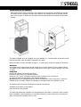
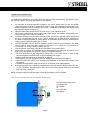
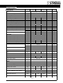
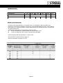
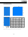
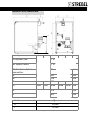
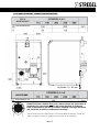
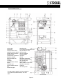
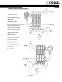
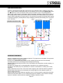
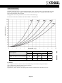
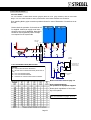
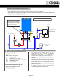
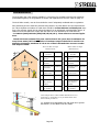
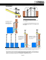
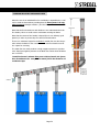
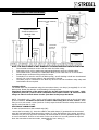
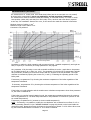
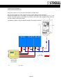
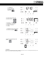
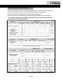
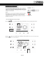
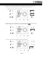
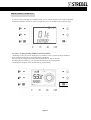
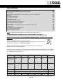
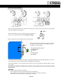
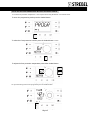
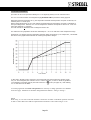
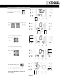
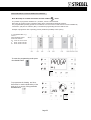
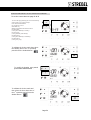
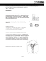
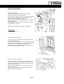
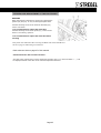
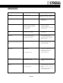
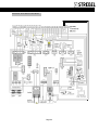
Strebel Condensing Boiler Range S-AF INSTALLATION & SERVICE MANUAL S-AF inst07:12DT Page NOTES Page 2 SAFETY GUIDELINES YOUR SAFETY IS OF PARAMOUNT IMPORTANCE. BE AWARE OF WHAT IS HAPPENING AROUND YOU AT ALL TIMES AND CONSIDER YOUR SAFETY AND THE SAFETY OF OTHERS. IN ADDITION ALWAYS ADHERE TO YOUR OWN COMPANY’S HEALTH AND SAFETY RULES Do not use in ear sound equipment other than hearing aids BE AWARE Beware of trip hazards. If in doubt ASK Do not carry out technical or cleaning work before disconnecting the Boiler from the electrical supply. Always position the general switch of the system and the main switch of the Boiler to “OFF”. Also switch off the gas and water supply, but only when the Boiler is not firing. Do not modify the safety or control devices without the authorization and the instructions of Strebel. Do not pull, remove, twist the electrical cables from the Boiler, even if they are disconnected from the electrical supply. Do not block or reduce the size of ventilation openings of the Boiler and of the room where the Boiler is installed. These openings are essential for proper combustion. Do not block the condensate drain. Do not leave containers with flammable substances in the room where the Boiler is installed. In case of a water leak isolate the Boiler from the electric supply, close the water supply and promptly inform the installer. When the Boiler is not used for a long period, carry out the following operations after consideration of frost protection of the Boiler and system. Position the main switch of the Boiler and the general switch of the system in the “OFF” position close the gas and water valves and drain the Boiler. Always consider frost protection. This manual is an integrated part of the Boiler. It must always accompany the Boiler, even if it is sold to another owner or user or transferred to another plant, Keep this manual save if it is damaged or lost, ask Strebel for another copy. WORK SAFELY Page 3 INDEX SAFETY ON DELIVERY OF THE PRODUCT THE S-AF BOILER DESCRIPTION SAFETY AND CONTROL DEVICES IMPORTANT INFORMATION 3 6 7 7 8 . 9 &10 11 12 13 14 15 TECHNICAL DATA TABLES BOILER DIMENSIONS & WEIGHT HYDRAULIC & GAS CONNECTIONS FLUE & AIR INTAKE CONNECTIONS S-AF EXPLODED VIEW SENSOR & CONTROL DEVICE POSITIONS 16 17 18 18 NEW INSTALLATION OR REPLACING AN EXISTING BOILER HEATING SYSTEM CONDITION SYSTEM WATER .. REQUIRED WATER CONDITION 19 19 20 21 22 to 26 AIR & DIRT SEPARATORS CONDENSATE DRAINAGE CIRCULATING PUMP LOW LOSS HEADERS SYSTEM LAYOUTS FLUES AND AIR INTAKES FLUE INFORMATION ... INSTRUCTIONS FOR THE ELECTRICIAN CONTROL CONNECTIONS EXPLAINED OUTSIDE SENSOR & COMPENSATION 0 TO 10 VOLT CONTROL ON OFF CONTROL CONTROL DISPLAY 27 28 to 30 31 32 & 33 33 34 35 36 Page 4 CONTROL AND GAUGE POSITIONS CONTROL BUTTONS 37 38 SETTING THE MODE OF ON/OFF OPERATION ON/OFF OPERATION FROM AN EXTERNAL CONTROL USING THE INBUILT TIMER CLOCK CONTROL 39 39 40 CONTROL COMMISSIONING TIME DISPLAY SET UP 41 42 & 43 SETTING IMPORTANT INITIAL PARAMETERS STARTING UP THE BOILER 44 45 & 46 ERROR SCREEN AND RE-SETS FAULT CODE TABLE 47 45 & 48 COMMISSIONING THE PREMIX MICRO-FLAME GAS BURNER INPUT GAS VALVE ADJUSTMENT 48 49 FROST PROTECTION TEMPERATURE 50 0 TO 10 VOLT CONTROL PROGRAMMING 0 TO 10 VOLT CONTROL 51 52 USING THE INBUILT CLOCK OPERATING PERIODS SETTING THE INBUILT CLOCK OPERATING PERIODS 53 54 TO 56 INFORMATION DISPLAYS CONTROL PARAMETER SETTING PROCEDURE/PROGRAMMING PARAMETERS 57 58 59 MAINTENANCE CLEANING THE BURNER CLEANING AND REPLACING THE ELECTRODES 60 61 62 PROBLEM SOLVING 63 INTERNAL ELECTRICAL DIAGRAM 64 Page 5 ON DELIVERY OF THE PRODUCT After reading all the safety instructions the installer should unpack and immediately check that the Strebel S-AF is complete and without any defects. Any damage should be reported immediately to the supplier or Strebel Ltd. The Boiler should be protected and re packed until the Boiler is fitted. The Boilers STREBEL S-A F are supplied in a single package on a wooden pallet, protected by cardboard and wooden crate. The Boiler is supplied in one piece. Beware the Boiler is Heavy see table on page 11. To avoid injury consider the weight of the Boiler. WARNING Use suitable safe working equipment and devices to remove the package and to handle the Boiler. The staples on the wooden crate should be made safe to avoid injury or cause damage to the boiler casing. HANDLING Remove the package and proceed as follows: Remove the front door (1) to facilitate handling. Insert two (2) 1” pipes of suitable strength into the housings or use a fork lift etc. (3) under the Boiler lift and handle it with suitable equipment. Do not dispose of the packaging material without consideration of the environment. It can be a potential source of danger. Dispose of packaging in accordance with the regulations in force. The Strebel S-AF includes the following documents and accessories: Installation instructions for the installer. User instruction (incorporated). The manual provided with the Boiler is an integrated part of the Boiler. It should be read carefully before installation and commissioning of the Boiler and kept for future reference or for when the Boiler is transferred to another owner or user. Page 6 THE S-AF BOILER DESCRIPTION These instructions are written for the installer of Strebel S-AF Boilers and contain all the necessary information for the specifying of S-AF boilers. Please read all these instructions fully. If you require further help please contact Strebel Ltd on 01276 685422 HIGH EFFICIENCY OPERATION The heating boilers from the Strebel S-AF series are heating boilers with maximum high efficiency. High performance is reached by using a special aluminium body of low water content and high heat exchange area to maximise energy efficiency and thermal output. The heat exchanger allows flue gases to cool down below condensation point, condensing the flue gases and releasing extra heat resulting in efficiencies of over 100%net calorific. The Boiler includes a stainless steel, total premix micro-flame burner that allows high modulation ratios, combustion stability, and low pollutant emissions NOx class=5 Also included is a variable speed fan for modulation of the air/gas mixture which also enables the Boiler to be flue and air intake “type C” room sealed) or “type B” chimney and Boiler room ventilation, both depending on the layout of the flue/ventilation adopted during the installation The control is provided with self-diagnosis with a display of error codes and operating parameters when a failure occurs. During design engineering, specific solutions have been adopted to obtain an optimum air/gas mix on a continuous basis reducing emissions and reducing noise . A control (stand alone Boiler ) that, if provided with an external sensor (at extra cost) located on a North Wall , allows compensation of the flow temperature based on the outdoor temperature. SAFETY/CONTROL DEVICES S-AF Boilers are provided with the following safety and control, devices. 1) Water pressure switch that stops the boiler operation when the pressure of the hydraulic circuit is lower than 1.3 (normal operating pressure is 1.5 bar) bar. 2) Condensate pressure switch that actuates when the flue pressure in the condense water trap exceeds 0.5 mbar. 3) Flue safety sensor that activates when the flue temperature is too high. 4) Gas pressure switch: that activates if the pressure of the supply gas is lower than 14 mbar. Note Gas pressure must be to current regulations. 5) Diagnosis of the hydraulic circuit: it protects the Boiler against any over temperature, checking the difference in temperature between flow and return (ΔT). If ΔT increases to 35°C: the gas input is reduced to the minimum value. If ΔT continues to increase the Boiler makes 5 re start attempts. If ΔT still increases to 35°C after 5 attempts the Boiler goes to lock out. 6) Manual reset safety thermostat: Max 110°C (0/-6). The Strebel S-AF Boiler adjusts to the demand for heat by using flame modulation and/or external controls, possibilities are 1) Built in 0 to 10 volt (0 to 10 volt signal from others) control. 2) Strebel optimiser control at extra cost. 3) Built in weather compensation (stand alone Boiler) with an outside sensor 4) Connection for any volt free ( the control circuit is 230volt ) control device. The boiler control is equipped with: Control for a DHW Cylinder (stand alone Boiler) with a diverter valve (spring return) or a pump ( a 3ph pump would require a relay DHW primary pump and relay not supplied) Connection for a Boiler pump, Pump included where quoted. Page 7 IMPORTANT INFORMATION For trouble free operation of the boiler, and to be assured of the full guarantee, the following items are required together with other stipulations in this manual: A. B. C. D. E. F. G. H I J K L M An automatic air and dirt separator installed in the return system side of a low loss header (alternative pages 25 & 26) or Strebel Boiler Guard (page 19) combined low loss header & air and dirt separator must be installed in the system . Installation of ancillaries and devices must be installed as shown on pages 21. Minimum static water pressure must be more than 1.5 bar. Maximum 6 bar . The system is fully flushed, free of water leaks, water tested, and additive utilised where necessary see pages 16 to 19 for information . The Boiler must be level. The Boiler must be vented, the auto air vent cap (where fitted) must be open. This automatic air vent is only used for bleeding the air from the heat exchanger of the boiler. External automatic air vent(s) and/or air separators must always be mounted in the heating system. Open all system auto air vents . Low and high water cut out pressure switches (usually in the fill unit) connected in the Boiler control circuit in series with other controls on terminals 1 & 2 ( 31&32) or by 0 volt when using external 0 to 10 volt control by others. See 34 Control of Boiler on/off must never be by interruption of the mains supply. When using a common flue (separate flues recommended) note when all the boilers are at high fire the flue system (see page 30) must be in negative pressure. S-AF flue gases have a low temperature (below 85°C), the boiler needs to have a high efficiency approved stainless steel or approved plastic flue system . Suitable condensate pipework as described on page 19 A gas supply to current regulations with local isolation. Gas connection see page 12 A pressure relief valve (PRV) is not provided with the Boiler. A PRV should be chosen to suit the system. A suitably sized expansion vessel (at extra cost) is required on all sealed systems. A flue gas test point (not on a bend) positioned twice the flue diameter distance from the Boiler flue connection. Example 200mm flue, site the test point 400mm away from the Boiler flue connection, see below. NOTE: A purpose made flue gas test point is normally provided by the flue supplier. Flue piece above the dotted line is not included in Strebel supply. 2D D Page 8 Flue gas test point by others D=200mm Flue 2D=400mm Or D=150mm Flue 2D=300mm TECHNICAL DATA Description 115 Fuel 150 unit II2H3p Boiler type Min gas consumption G20 G31 280 EU Boiler category Net efficiency at max Pn (80°-60°) Net efficiency at min Pn (80°-60°) Net efficiency at max Pn (50°-30°) Net efficiency at 30% (30° return) Max gas consumption G20 G31 240 G20 (20 mbar) -G31 (37 mbar) Destination country/countries Nominal input max (Qn) Input min (Qmin) Nominal output (80°-60°) (pn) Nominal output (50°-30°) Output min (80°-60°) (pmin) Efficiency 200 B23, B33, C43, C53, C63, C83 115.9 21.0 111.8 119.0 20.0 150.0 30.0 146.7 156.1 29.0 200.0 35.5 196.0 207.8 34.7 240.0 42.5 234.0 249.1 41.5 280.0 49.5 271.9 290.6 48.3 kW kW kW kW kW 96.5 95.0 102.7 107.6 12.26 9.01 2.17 1.59 97.8 96.5 104.1 107.5 15.87 11.66 2.91 2.14 98.0 97.7 103.9 107.5 21.16 15.54 3.76 2.76 97.5 97.6 103.8 107.5 25.40 18.65 4.50 3.30 97.1 97.5 103.8 107.5 29.63 21.76 5.24 3.85 % % % % m3/h kg/h m3/h kg/h Emissions Flue temperature (80°-60°) max 65 -70 °C Flue temperature (80°-60°) min 60 -65 °C Flue temperature (50°-30°) max/min Flue gas mass flow at Qn (80°-60°) Flue gas mass flow at Qmin (80°-60°) Condensate production max CO2 max G20 G31 40 -45 0.054 0.0101 15 0.074 0.0144 19 CO2 min G20 G31 CO NOx 15 20 NOx class 0.094 0.0170 25 °C 0.112 0.0204 30 0.131 0.0237 36 kg/s kg/s l/h 9.0 -9.3 % 10.6 % 8.7 -9.0 % 10.3 % 20 -50 ppm 18 18 18 5 ppm - Electrical Data Electrical power absorbed 225 260 Power supply voltage 320 320 320 230 ~ 50 Protection degree W Volt ~ Hz X0D IP Maximum heating pressure 6 bar Maximum operating temperature 90 C° Boiler Heating water content Pressure Loss water side ∆T 20 15.3 18 22.9 25.6 28.4 l 80 80 90 90 100 mbar ΔT IDEAL /MAXIMUM Flow / Return 20 / 35 Water flow rate ΔT 20 4.98 Water flow rate ΔT 10 9.97 Flue Exhaust Chimney connection 150 °C 6.45 8.60 10.32 12.04 m3/h 12.90 17.20 20.64 24.08 m3/h 150 200 200 200 Ø Page 9 Page 9 TECHNICAL DATA Description 115 150 Air connection Maximum length of flue & Air Intake 200 240 280 100 28 24 20 unit Ø 16 10 m RESIDUAL FAN PRESSURE For Boilers using individual flues ( not common flues ) it is possible to utilise the Boiler’s fan pressure to overcome the resistance of longer flue runs and smaller diameter flues, in this case the flue could be in a pressure condition. The air supply and the flue exhaust must be in an equal pressure area IE same wall. Looking at the table below a 115 Kw Boiler could have either A) 28 mts of 150mm flue exhaust and take air from the Boiler room. B) 14 mts of 150mm flue and 14 mts of 100mm ducted air intake. 90 & 45 degree bends are equivalent to 1.5 mts of flue See flue and air connection sizes on page 13. See Flue information on pages 27 TO 30. Page 10 BOILER DIMENSIONS & WEIGHT SIDE H W D MODEL WIDTH W mm DEPTH D mm HIGH H mm WEIGHT KG 120-4 640 1100 1200 180 160-5 640 1100 1200 190 200-6 640 1320 1200 240 240-7 640 1320 1200 257 280-8 640 1320 1200 274 PLAN Please Note: The above plan drawing includes the vertical flue connection in measurement D Page 11 HYDRAULIC & GAS CONNECTIONS J G H Description 115 150 200 240 280 MI System flow 2” M RI System return 2” M AS Condense Siphon connection A 25 mm 400 mm B 728 mm C 160 160 230 230 230 mm D 848 848 1088 1088 1088 mm E 279 mm F 363 mm G Gas connection 11/2” H 624mm J 245mm Page 12 FLUE AND AIR INTAKE CONNECTION DIMENSIONS STREBEL S-AF FLUE DIMENSIONS Internal Diameter F F Flue AirIntake Intake Air Air Intake: S = 60 mm AIR INTAKE Spigot Diameter AI s STREBEL S-AF 100 IT Install horizontal exhaust Flue parts with at least 5.2% (more than 5 centimetre for every linear metre) fall in the direction of condense traps. A maximum of 2.5 mt run of flue is allowed if no traps are fitted and the boiler is used for condensation drainage. AI The air intake can be if required used to room seal the Boiler according to current regulations or Boiler room air (to regulations) can be used in the normal way. Page 13 S-AF EXPLODED VIEW 1 Front door 2 Gas valve 3 Gas pressure switch 4 Siphon pressure switch 5 Water pressure switch 6 Return probe 7 Manometer connection 8 Return manifold 9 Fill and drain cock 10 Foot 11 Wheel 12 Condensate exhaust siphon 13 Water trap 14 Flue exhaust connection 15 Gas feed pipe 16 Boiler body 17 Cleaning and inspection door 18 Automatic air vent 19 Flow probe 20 Flow manifold 21 Upper panel 22 Burner 23 Fan 24 Ignition electrodes 25 Flame detection probe 26 Terminal strip 27 Side panel 28 Air intake or Connection 29 Boiler component container 30 Control panel The gas pressure switch 3 can be mounted in one of the two positions shown, see next page. PLAN VIEW Page 14 SENSOR & CONTROL DEVICE POSITIONS 1 Automatic air vent 2 Flow temperature sensor 4B 3 Boiler body 4 Gas pressure switch 4B Alternative position of Gas pressure switch located at gas valve 5 Pressure gauge connection 6 Return temperature sensor 7 Water pressure switch 8 Boiler drain cock 9 Condensate drain siphon 10 Safety thermostat 11 Boiler body sensor 12 Flue temperature sensor M1 Water flow R1 Water return Page 15 NEW INSTALLATION OR REPLACING AN EXISTING BOILER Select the position for the Boiler Select a position in the building with adequate access to the front and side of the boiler (for future maintenance and servicing) mounting on a non combustible floor. On every side of the boiler at least 50cm of clearance should be applied to walls or wall units, 50 cm above the top side of the boiler CONSIDER THE FOLLOWING Determine the positions for the flow and return . The Boiler is Heavy see table on page 11. To avoid injury consider the weight of the Boiler, The Boiler must be level. The following should be considered: Flue System. Confirm that the flue system (see pages 27 to 30) is suitable for the new condensation Boiler, designed and built in accordance with the regulations, as straight as possible but sloping to drains, room sealed, insulated, without obstructions or narrowing and fitted with connection drains for the condensate Gas pipe connections . Confirm that the gas supply pipework is in accordance with the specific regulations. Air supply system and connections. Confirm the ventilation is to regulations. Flow and return pipe connections. Check that the hydraulics are sound, the system is washed, clean of mud and build ups and the supply water system is as described Pages 16 TO 19 The system is provided with efficient devices removing air and impurities up to 5 μm e.g. , micro impurity separators and micro air bubble separators or a Strebel Boiler Guard see page 19 . Check that the Hydraulic system is installed correctly and is to current regulations. If the system is: 1) Old and has leaks resulting in poor water quality 2) Unable to handle 1.5 bar 3) Utilising plastic material for the flow and return from the radiators or under floor heating and is not oxygen diffusion proof to DIN standard 4726/4729, a separation between the central heating water of the boiler and the system will be required, using a plate heat (see Illustrations on page 25 & 26 ) exchanger . This will prevent contamination of the boiler heat exchanger with magnetite, dirt etc. In the instances 1,2 &3 failure to provide such separation could void the warranty. It is essential to prevent possible air intake and water leakage of the central heating system. Fresh oxygenated water could damage the heating system and the heat exchanger of the boiler and should therefore be prevented! Check that the electrical system is carried out by qualified engineers in accordance with current regulations. Condensate and pressure relief valve drainage notes see notes on page 19 Power supply: preferably the electrical isolator should be positioned near the boiler. The Boiler pump is fitted on site by others to suit site conditions The pump should have local isolation by others and connected to the Boiler terminal strip preferably via a relay by others see page 31. Confirm that the electrical system is carried out by qualified engineers in accordance with current regulations. Check that the Expansion vessel is sized correctly for the system Page 16 NEW INSTALLATION OR REPLACING AN EXISTING BOILER The safety valve outlet must route to the drainage system. The manufacturer is not responsible for any flooding due to the breakdown of the safety valve. The choice and the installation of the system components are made by the Installer who must comply with the standards in force and the rules of good practice. Always install isolating valves so that the boiler can be isolated from the heating system when needed. Make sure that the safety valve is mounted between the boiler and the isolation valves. The pressure relief valve/ safety valve must always be installed in such a way that it cannot be isolated from the boiler by a valve. The specifications and size of the safety valve should be determined by the installer/designer and must comply with all applicable regulations . By-pass There is no inbuilt By Pass in the Boiler. Low loss headers (or Strebel Boiler Guard page19) should be used for the S-AF See page19 & 21, if this is not practical contact Strebel. Pump function The Boiler pump controlled from the boiler starts running when there is a heat demand. When a heat demand stops, the pump will continue to run for a programmed time . . Frost protection The boiler has built-in frost protection, that automatically activates the boiler pump (in a frost condition when the Boiler (water) temperature drops below 5°C (programmable). When the boiler return temperature drops below the 3°C (programmable), the burner is also ignited. The pump and/or burner will shut down as soon as the return temperature has reached 10°C (programmable) this function protects the Boiler. The stated temperatures are related to the temperatures measured by the RETURN sensor of the boiler. This frost protection function will not fire up the boiler in case of a “general blocking” of the burner This “Frost Protection” function is for the boiler and not for the whole central heating system. A boiler or system damaged by frost is not covered under warranty. Fill the condensate drain siphon Item 9 page15 before firing the boiler. Heating System Water Condition The natural chemical constituents found in supply water can vary in identity and concentration over a large range of values depending on the source location or season. The supply water may have effects on the efficiency of heating systems. Some constituents may be detrimental depending on their concentrations. The effects of constituents in water can result in metal corrosion, circulating particulate debris, settled sludge, poor water flow or blockage and degradation of boiler parts. These effects can be avoided by cleaning and flushing and the application of water treatment and periodic system water maintenance. Cleaning Heating circuits should be thoroughly cleaned and flushed prior to commissioning or following major remedial works .The type and extent of debris, dirt and fouling commonly found inside central heating circuits largely depend on the age and nature of the system. A thorough system clean not only restores system efficiency and effectiveness, but is critical in preparing interior surfaces for effective corrosion and scale inhibition that effect the Boiler. Before cleaning, the system should be examined to determine the system configuration, the age and overall condition of components and the nature of the contamination that needs to be cleaned in order to decide the most appropriate cleaning agent and cleaning method. Chemical corrosion inhibitors should be added during the final fill of the system at a concentration recommended by the inhibitor manufacturer. It is important that full circulation and homogenous distribution of the additive is achieved before sampling system water to confirm the correct inhibitor concentration, and subsequent adjustment if necessary. Strebel recommend Sentinel Products Page 17 SYSTEM WATER Before opening the Boiler isolation valves always confirm that the system is acceptable, one or more the following options should have been observed. 1) Fully power flushing of the complete hydraulic system 2) The use of the water already present in the plant is good as it complies with notes on Water Condition and notes on pages 16,17 and below. 3) Chemical washing of the plant, by using mains water with the addition of a detergent because of a clogged system . In the case of 1 or 3 above fill the system with new treated water. REQUIRED WATER CONDITION The pH must stay between 6.5 and 8.5. The maximum permissible content of chloride is 250 mg/l. The total quantity of water to be used, including topping up, with a total water hardness of 20°F, must not exceed 20 litres/kW. If the water hardness exceeds 20°F, use the following formula to calculate the total quantity of water to be used: (20°F/hardness in °F) x 20. Example with water hardness of 30°F: (20/30) x 20 = 13.5 l/kW In this example if the total quantity of water (system + topping up) is higher than 13.5 l/kW, it is necessary to soften the water. The water may only be partly softened until a value of 25% of the initial value, so if the initial hardness is 30°F, it may only be softened to 7.5°F. NOTE: If the water hardness is expressed in °D, the conversion factor is 1°D=0.56 x °F. If the analysis of a sample of water that will be used to fill the system is within the values indicated, the system can be used, otherwise an inhibitor must be used. For systems operating at low temperature only, add an inhibitor against bacterial proliferation. WARNING Do not soften the water according to the principle of ion exchange. Never fill the plant with distilled or demineralised water because it corrodes the aluminium heat exchanger severely. If the plant is filled and topped up with softened water to reduce the total hardness the water must be conditioned in order to keep the pH within the correct threshold to avoid any corrosion. Use a log book to record water filling, refilling and topping up, water quality measurements, and water treatment. Install a water meter to check the amount of filled, refilled and topping up water. The conductivity of the non treated plant water must not exceed 600 µs/cm. If the water of the system is treated, the instructions of the manufacturer of the product used must be followed. The conductivity must not exceed 2000 µs/cm. NOTE: If the conductivity is higher than the values indicated above, flush the system, rinse, and fill with clean tap water, adding the recommended products. If an automatic filling system is used, a water meter should be provided in order to identify any leak . Do not drain the water from the system during ordinary maintenance, even if the quantity is small for example, for filter cleaning, Always provide the Hydraulic system with suitable isolation valves. Systems filled with anti-freeze agent require the use of a plate heat exchanger Page 18 AIR & DIRT SEPARATORS Consider a Strebel Boiler Guard (BG) combined low loss header/dirt and air separator (shown below) or install a strainer (water filter) and/or a dirt separator in the return pipe system side of the low loss header in such a way that the water going to the boiler is free of any debris/particles. When using a water strainer or BG always check a week after installation to determine the strainer/ BG cleaning interval. Mount valves before and after all devices, Fit air bleed valves. Even when fitting air and dirt separators the system water is very important (see page 16) blocked and/or partially blocked exchangers, including failures and/or damages caused by such blockage are not covered by the warranty. STREBEL BOILER GUARD The Strebel Boiler guard acts as a low loss header dirt and air separator and if a magnet set is (at extra cost) fitted a magnetite separator. CONDENSATE DRAINAGE Points to remember when routing condense pipework. The pipework must be plastic. Run pipework sloping to outside as steeply as possible. Be aware that condensate can freeze so where possible pipework should route internally. Increasing pipework size could help prevent blockage from freezing. Pipework running externally should be as short as possible and insulated also consider avoiding exposed positions. Consider trace heating which is thermostatically controlled for the condensate pipework. Consider an automatic pump unit specifically for removal of condensate if no drain point is easily accessible. Ideally condensate should route to the sewer drain complying with local and national regulations. BS 6644 states Alternatively, the condensate can be discharged into the rainwater system or a purpose-made soak-away. Always comply with local and National regulations and if in doubt contact the appropriate authority. Strebel will commission Boilers on the understanding that the suitability of the condense drainage system is checked by others and that compliance is always checked by others. Page 19 CIRCULATING PUMP The Boiler pump must always be energised from the Boiler as the advanced control system checks that the pump starts up when energised. The pump is connected to the boiler (terminals 3 & 4, see page 31) by others using relays and local isolation where required. The graph below shows the pressure loss curves of the S-AF Boiler range. PRESSURE DROP mbar PUMPS PROVIDED BY STREBEL ARE MATCHED TO THE BOILER FLOW RATE m3/h STREBEL S-AF Description 115 150 200 240 280 Water flow rate m /h @ ΔT 20 degrees 4,98 6,45 8,60 10,32 12,04 m /h Water flow rate m /h @ ΔT 10 degrees 9,97 12,90 17,20 20,64 24,08 m /h 3 3 WARNING Non compliance with the water flow rates recommended may cause malfunctioning of the Boiler. Upon commissioning check the rotation of the pump shaft. DO NOT operate the pump without water. Replacement pumps must have an amperage below the fuse installed in the control board (3.15A). Page 20 3 3 LOW LOSS HEADERS Low Loss Header Low Loss Headers or Strebel Boiler Guards (page19) MUST be used (page 25differs) with the S-AF Boiler Range. Low Loss Header details are below, Strebel Boiler Guard details available from Strebel ltd. Floor standing Boilers ,pipe connection positions shown for ease of illustration. Connections are at the rear. Please check the quotation for items that will be supplied. Strebel can supply most items shown at extra cost if applicable. Note NRV’s should be used supplied by others. Pumps are required for the system side Pcontrol Pcontrol S-CB Boiler S-CB Boiler On Board Boiler Pump On Board Boiler Pump LOW LOSS HEADER AAV SV SV CO SV CO AAV GAS DOC DP DAS H1 H3 GAS D1 DOC H2 D4 D1 DOC Strainer Interlock with boiler DOC Pressurisation Unit With High & Low Pressure Switches Low Loss Header & Flow/Return sizes Legend: H1 = System Flow & Return Dimension. H2 = Flow & Return Header Dimension (boiler side of LLH) H3 = Low Loss Header Height D4 = Low Loss Header Diameter D1 = Diameter of common Flow & Return Headers AAV LNE Heating Expansion Vessel DOC DOC Boiler Connection Sizes see page 12 Note to Design Engineer: See quotation for equipment supplied Please check regulations in force relating to fill systems Also see information on pages 16 to 18 Page 21 TYPICAL SINGLE BOILER SYSTEM LAYOUT Floor standing Boilers ,pipe connection positions shown for ease of illustration. Connections are at the rear of the Boiler. The Low Loss Header could also be in a vertical position with the AAV in the correct place at the top. Also see information on pages 16 to 18 P control S-CB Boiler Please note that all equipment connected below the dotted line is not supplied with the boilers as standard. These are available at extra cost from Strebel . On Board Boiler Pump Interlock with boiler LNE Pressurisation Unit With High & Low Pressure Switches GAS LINE CO DOC Heating Flow & Return SV DOC AAV LNE AAV P1 Low Loss Header Heating Expansion Vessel DOC DAS Strainer See pages 21 for more Hydraulic information & Low Loss header Sizing LEGEND: DAS = Dirt & Air Separator P1 = Heating Pump/s SV = Safety Valve - ¾” - 3bar CO = Condense Drain in plastic via a tundish AAV = Automatic Air Vents DOC = Drain Off Cocks Boiler Connection Sizes see page 12 Please check regulations in force relating to fill systems DOC DOC System Notes: S-AF Boilers must be installed using a Low Loss Header and the use of an Dirt & Air Separator (ALTERNATIVE SEE PAGE 19 ) is compulsory. A Strainer must be installed on the Return Pipe-work. The use of a Temperature Gauge on the Flow is advisable. The boiler is fitted with an Air Vent to vent the Boiler not the system. Also needed are Auto Air Vents as shown and fitted to all high points, and recommended are Drain Off Cocks fitted to all low points of the system. Minimum system Pressure is 1.5 bar. if less pressure is available, see page 25 & 26 or contact Strebel Technical Department for further advice. Page 22 2.2 TypicalCASCADE Cascade Boiler System Layout TYPICAL SYSTEM Pcontrol Pcontrol S-CB Boiler Please note that all eq u ip men t con n ect ed below the dotted line is not supplied with the boilers as standard. These are available at extra cost from Strebel. S-CB Boiler On Board Boiler Pump AAV AAV DOC CO DOC SV DOC SV GAS DOC DAS On Board Boiler Pump CO DOC SV GAS DP S-CB Boiler On Board Boiler Pump CO DOC SV Pcontrol S-CB Boiler On Board Boiler Pump CO FTS Pcontrol GAS DOC GAS DOC DOC LOW LOSS HEADER Strainer Interlock with boiler DOC Floor standing Boilers ,pipe connection positions shown for ease of illustration. Connections are at the rear. Pressurisation Unit With High & Low Pressure Switches AAV LNE Heating Expansion Vessel Also see information on pages 16 to 18 DOC See page 19 for more Hydraulic information & Low Loss Header Sizing LEGEND: DAS = Dirt & Air Separator FTS = Flow Temperature Sensor SV = Safety Valve - ¾” - 3bar CO = Condense Drain in plastic via a tundish AAV = Automatic Air Vents DOC = Drain Off Cocks DP = Dosing Pot Boiler Connection Sizes see page 12 Please check regulations in force relating to fill systems DOC System Notes: S-AF Boilers must be installed using a Low Loss Header or Strebel Boiler Guard., note special exception relating to plate heat exchanger use as shown on page 25 & 26 could apply, consult Strebel. The use of an Dirt & Air Separator is compulsory. A Strainer must be installed on the Return Pipework. Or consider a Strebel Boiler Guard. The use of a Temperature Gauge on the Flow is advisable. The boiler is fitted with an Air Vent. To vent the Boiler not the system .Auto Air Vents should be fitted as shown to all high points, and Drain Off Cocks fitted to all low points of the system. Minimum system Pressure is 1.5 bar if less pressure is available, see page 25 & 26 and contact Strebel Technical Department for further advice. Page 23 ROOF TOP BOILER ROOM Pipework layout for a roof top plant room with pipework and AAV’s higher than the Boilers by at least 0.5 Mt Pcon- Pcon- Floor standing Boilers ,pipe connection positions shown for ease of illustration. Connections are at the rear. Boiler Connection Sizes see page 12 Please check regulations in force relating to fill systems Page 24 BOILERS WITH SEPARATION FROM THE SYSTEM Floor standing Boilers ,pipe connection positions shown for ease of illustration. Connections are at the rear. Flow Proving Please check regulations in force relating to fill systems Strebel recommend using a low loss header on this type of system as shown on page 26 therefore no flow proving or closed loop would be required. If space dictates otherwise see below. Size the primary loop circuit pump to cater for the total mass flow of all the Boilers at 20c delta T. The pump head is sized to overcome the plate resistance. The Boilers should not start up until the main loop pump is proved by the Flow Proving switch, supply, fitting and control connection logic by others Size the Common flow & return headers using the information on page 21. Boiler connection sizes see page 12 System side pumps are sized to overcome the Plate Heat exchanger and any system side resistance Any difficulty with existing system pump’s can be overcome by using a pumped Low Loss Header. At the system side and existing system pumps. The system side can be open vented with normal precautions (we strongly recommend sealing the system to prevent any possibility of pump over) or sealed using the relevant equipment. Page 25 SIMPLE SEPARATION OF BOILERS FROM THE SYSTEM System side pumps are not shown but they should be sized to overcome the system resistance and the plate resistance. A further low loss header and pump could be used (system side of the low loss header) if the system side pumps cannot overcome the plate resistance ,contact Strebel. Pcon- Pcon- Pcon- Please check regulations in force relating to fill systems Floor standing Boilers ,pipe connection positions shown for ease of illustration. Connections are at the rear. Boiler Connection Sizes see page 12 Page 26 FLUES AND AIR INTAKES NON ROOM SEALED BOILERS Ventilation to BS6644 (2005) IGE/UP/10 (ed 2) SEE CURRENT REGULATIONS. BS5440 is not applicable to the S-AF. ROOM SEALED BOILERS (Type C as defined by B.S 6644 2005 ) Installation in a boiler room. The ventilation provided shall be adequate to ensure that the boiler room temperature meets the requirements as follows: The air supplied for boiler room ventilation shall be such that the maximum temperatures within the boiler house shall be as per current regulations: — 25 °C at floor level (or 100 mm above floor level); — 32 °C at mid-level (1.5 m above floor level); and — 40 °C at ceiling level (or 100 mm below ceiling level). Ventilation must be to BS 6644 MULTIPLE BOILER INSTALLATIONS separate flues provide the most efficient operation on any multiple Boiler system. Common flues must be in negative pressure see pages 28 to 30. When the boiler room or fitting space complies with the relevant ventilation requirements, boilers can be non room sealed i.e. exhaust only, providing ventilation complies with current regulations Alternatively S– AF Boilers can be used in a room sealed application. See page 13 for flue connection details. WARNING The Boiler normally intakes air from the boiler room IT MUST BE PROVIDED with ventilation in accordance with regulations in force. If the Boiler is room sealed the Boiler room must have compartment ventilation. DO NOT block or reduce the size of ventilation openings of the boiler room or of the Boiler. It is recommended to use flue’s complying with EN1856-1 and EN 1856-2. The flue must comply with the regulations in force, and be fitted with condensate drains. The flue should give a negative pressure at the connection with the Boiler The boiler condensate must only drain the condensate from the boiler and a short flue run. Flues over 2.5 mts need extra syphon u traps. Supply and route the discharge pipework from the Boiler water trap to a drain. The Flue system must be suitably sized for condensing units. Unsuitable or wrongly sized flue systems can generate combustion problems and create noise. Tilt the flue exhaust by 5.2% and towards condense traps. The BOILERS STREBEL S-AF are provided with 1) A flue exhaust temperature sensor that in case of abnormal increase in temperature immediately stops the operation of the unit. 2) A Condensate pressure switch that actuates when the flue pressure in the condense water trap exceeds 0.5 mbar. See page 19 relating to condense Page 27 FLUE INFORMATION The S-AF Boiler has a fan pressure capable of overcoming Flue resistance and Air inlet resistance (both added together) for single Boilers or Boilers with separate flues. See the Table on page 10. The S-AF Boiler usually uses air from the Boiler room if adequately ventilated and to regulations. Flue positioning should avoid flue products being drawn in by other Boilers see the information below. When Separate air intakes are used these should be at least 600 mm and ideally 1mt away from a flue exhaust. Supply Air can always be taken from an adequately ventilated Boiler Room. Installers must check that Flues comply with the clean air act as defined by the local authority . See BS6644 (2005) BS5440 (2000) IGE/UP/10 (ed 2) Flues must be to current regulations. Install horizontal exhaust Flue parts with at least 5.2% (more than 5 centimetre for every linear metre) fall in the direction of condense traps. If the boiler is used for condensation drainage a maximum of 2.5 mt run of flue is allowed when no extra condensate traps are fitted . Above 70 Kw net input Below 70kw net input Distance from Distance from G P P D W V C A M 2000mm G W Side of opening 1000 mm Window. W Side of opening 300mm Window. A Adjacent to a Terminal. A Adjacent to a Terminal. V Vertically from 1500 mm a Terminal. V Vertically from 1500 mm a Terminal. C Internal or External Corner. 300 mm C Internal or External Corner. 300 mm P Roof Line. 600 mm P Roof Line 600 mm Co axial flue/air 600mm inlet, above a window. D Co axial flue/air 500mm inlet, above a window. M Below an open- 600mm ing window. M Below an open- 300mm ing window. G D 600mm 600mm Above Ground 600 mm Above Ground 2000mm 300 mm This example shows a Flue exhaust distance from a Co axial flue. Co Axial flues or any air intake must never draw exhaust products in. Co Axial flue is for information only The S-AF has a separate flue and air ( or uses Boiler room air ) intake Page 28 FLUE OPTIONS 600mm 600mm 600mm 600mm C Through the wall flue, room sealed with compartment ventilation as regulations E A Flue distances from Walls & Air Intakes C = Co-Axial Flue E = Exhaust (also 600mm from a parapet wall) A = Air Inlet Co Axial flue is for information only. The S-AF has a separate flue and air ( or uses Boiler room air ) intake. Through the roof flue room sealed with compartment ventilation as per regulations. Through the roof flue with Boiler room ventilation from outside as per regulations. > 300mm The air intake must be from a correctly ventilated room or consider a ducted (plastic flue pipe complies) air inlet from a position on the same wall 600mm away from the exhaust and 300mm from ground level. Check the flue and air inlet information for Boilers having there own (not common flues) flue, see pages 13, 27 to 30. Flue positioning should avoid flue products being drawn in by other Boilers . When Separate air intakes are used these should be at least 600 mm and ideally 1mt away from a flue exhaust. Supply Air can always be taken from an adequately ventilated Boiler Room. Page 29 COMMON NEGATIVE PRESSURE FLUES When the use of an individual flue for each Boiler is impossible the S-AF can be used as shown below providing that the flue system is in negative pressure (draught condition ) and has adequate condensate drain points. Note that the flue branches to each Boiler are not underneath the main flue header, this is to avoid excess condensate entering the Boiler. Note that the common flue header is sloped (this is now industry good practice) in order to protect any flue seal from deterioration. There is no minimum height for the Boiler’s vertical flue riser but the position where the Boiler’s riser connects to the main flue header must allow space for servicing. The main flue riser must produce enough negative pressure to produce more than 3pa negative pressure at the Boiler flue outlet when all Boilers are on full fire. Install horizontal exhaust Flue parts with at least 5.2% (more than 5 centimetre for every linear metre) fall in the direction of condense traps. 60mm Page 30 600 mm INSTRUCTIONS FOR THE ELECTRICIAN ALARM INDICATION (WHEN PROGRAMMED) 230v TB ON/OFF CONTROL 230volt terminal 1 out REMOVE LINK TA NOT USED BOILER PUMP OUTSIDE SENSOR See note INTERNAL USE NOTE: THE BOILER PUMP IS NOT NORMALLY THE MAIN HEATING CIRCULATION PUMP The electrical connections to the S-AF are within the boiler casing. Connections must only be made using appropriate diameter multi core flexible cables. The outside sensor (normally for a stand alone Boiler) is not used with 0 to 10 volt control. Strebel always recommend using relays for Pumps. Terminals 3 & 4 must be used for the Boiler pump ( as self checking is built into the advanced control) 3 & 4 can energise relays in the main panel if required. The Boiler pump is connected to the Boiler by others to suit site conditions using relays and local isolation where required. Connector Block The stated items may be attached using the connections above, use relays (not supplied) for a 3 PH Boiler pump. Please pay attention to the Earthing of all components Important: Interruption of the mains supply for On/Off control must not be used. Safety devices (volt free ) can be series connected in the control circuit 1 & 2 but not when using 0 to 10 volt control where 0 volts (less than 3volts) stops the Boiler. NOTE :Terminals 1 & 2 ( 230v ) are for on/off control and safety devices such as low & high water pressure switches. Terminals 1 & 2 have no effect when using 0 to 10 volt control. When using 0 to 10 volt control 0 volts (less than 3 volts) stops the boiler therefore safety devices should signal 0 volts (less than 3 volts). ELECTRICAL CONNECTIONS In order to have access to the terminal strip (MC): remove the front casing (1); insert the cables in the cable clamps (2) positioned over the terminal strip (MC) and make them pass through the conduit (3) in the internal part of the casing. An electrical knock out (K.O.) box (by others if wanted) can be mounted on the rear galvanised casing to cover item 3 termination. First use a hole cutter on the rear of the K.O. box and grommet as required. Once the connections have been made, reassemble the front casing (1). Page 31 CONTROL CONNECTIONS EXPLAINED 1&2 ON—OFF CONTROL OF THE HEATING BOILER After removing the link in terminals 1 & 2 a volt free control devices can be connected (not usable with 0 to 10 volt control see pages 13 & 14) The circuit is 230v live out from terminal 1. 3&4 BOILER PUMP The Boiler pump is energised from these terminals. The pump is sited to suit site conditions and requires materials and connection by others. 3 phase pumps require connections and a relay by others. Strebel recommend relays for pumps 5&6 NOT USED These terminals output 230v for an external device (0.5 amp) but not when the boiler is switched off. 7&8 ALARM INDICATION OR DHW PRIMARY PUMP The outputs of the terminals 7-8 parameter 04 can : 1) be configured to control .the management of an alarm signal .PM 04 = 7 alarm management 2) be for a stand alone Boiler and power a (sensor required at extra cost) DHW primary pump. For DHW PM 04 = 4 pump control 9 & 10 OUTSIDE SENSOR Direct compensation on (stand alone boiler) boiler using a sensor at extra cost. See next page. 11 & 12 CALORIFIER SENSOR or THERMOSTAT WHEN PM4 =PUMP CONTROL When a calorifier is installed and the primary pump is controlled by terminals (7 & 8) on the Boiler (single Boiler installation) a hot water sensor must be connected to these terminals when PM 04 = 4 pump control . Not normally used on multiple boiler installations. 13 & 14 0 to 10 VOLT CONTROL A 0 to10 volt (see page 34) source ( from others ) will modulate the boiler temperature. 0 volts (less than 3 volts) being Off & 10 volts being maximum boiler temperature as programmed. 0 to 10 volt control is recommended for BMS . Terminals 1 & 2 have no function when using 0 to 10 volts. 15 & 16 Not used Page 32 OUTSIDE SENSOR (OPTIONAL) The outside sensor is usually used with stand alone boilers (and is not used with 0 to 10v control) for direct boiler compensation, but is not required for normal operation if unwanted The outside sensor must be installed outside the building, on a flat wall surface, on a north or north -west position (colder side) and away from flue hoods, doors, windows and areas directly exposed to sun rays. For installation: Remove the cover, fix the sensor then make the electrical connections Boiler Temperature Minimum section of cables: 1 mm2 Maximum length of the cables: 50 m. Connectors non polarized External Temperature Procedure to enable the boiler operation with an external sensor (variable temperature) and night set back, if required, it is necessary to change parameters. See page 58. Set parameter 15 by choosing a curve with a suitable coefficient K see the graph above. Set parameter 23 (Night function) at a value (e.g. 10°C). The parameter 23 reduces the set temperature calculated by the boiler, according to the curve K chosen and the degrees set in this parameter. The night reduction is activated by opening the contact TA ( 1 and 2) or selecting the operating period on the boiler panel. If necessary, set parameter 7 by choosing the maximum temperature of the boiler regardless of the temperature calculated. If necessary, set parameter 27 by choosing the minimum temperature of the boiler regardless of the temperature calculated. If the boiler is in night reduction and the outside sensor calculates a temperature lower than parameter 27, the boiler is switched off. If the boiler is in comfort (normal Heating) mode, the temperature maintained becomes the temperature set by parameter 27. The boiler stays switched on until parameter 21 intervenes (summer to winter outside temperature). If necessary, set parameter 21 (summer to winter outside temperature). NOTE: If necessary, it is possible to modify the set calculation with a selected curve offset of +15 or 15°C by actuating trimmer P3 (see “WIRING DIAGRAM” on page 64) directly on the board inside the electrical housing. Rotate the trimmer clockwise to the maximum to obtain a +15°C offset. When rotating the trimmer anticlockwise to minimum a -15°C offset is obtained. Page 33 0 TO 10 VOLT CONTROL Simple control idea for 0 to 10 volt control of One Boiler or Multiple Boilers Note: No power supplies etc. shown. All Boilers require a power supply etc and local isolation. Common fault indication 230v on terminals 7 & 8 .Terminals 1 and 2 have no function when using 0 to 10 volt operation. The Boiler pump is wired back to the Boiler control panel with isolation (all by others) to suit site conditions and requirements. A parameter change is required PM 18 to display 07 see page 51 and 52. Pcon- Pcon- Pcon- 0 to 10v control wiring BMS CONTROL with 0 to 10v control regime BY OTHERS BMS Control and wiring by others Page 34 13 14 ON/OFF CONTROL The following drawing shows a simple control idea for the S-AF . Simple Relay control (using volt free contacts ) of the S-AF. The relay makes terminals 1 & 2 (230volt )in each Boiler. All other control and safety devices control the relay. Common fault indication 230v on terminals 7 & 8. One or an unlimited number of Boilers can be activated using this control system providing each Boiler has its own clean relay contacts. No external temperature sensor fitted therefore no compensation. No function when using 0 to 10 volt control Note: No power supplies or isolation etc. shown. All Boilers require an individual power supply etc. and local isolation. The Boiler pump is wired back to the Boiler control panel with isolation (all by others) to suit site conditions and requirements. Pcon- Pcon- Pcon- Relay with clean contacts Relay & optimiser by others Page 35 CONTROL DISPLAY Internal clock operation is defeated in HEATING STAND BY DHW mode. ENERGISED FAULT NOT USED BOILER ON BOILER OFF HALF HOUR 1 SEGMENT ONE HOUR 2 SEGMENTS VALUES TIME OR SELECTED PARAMETER FLAME LEVEL DAY OF WEEK AUTOMATIC OPERATION SLEEP MODE CONTROL OPERATION USING TERMINALS 1& 2 OR 0 to 10 VOLT OPERATION WHEN PROGRAMMED Page 36 NOT USED CONTROL AND GAUGE POSITIONS Tp1 Control Option Position lu User interface lp On/Off switch with indication light Fu Main fuse (6.3 A) Mn Pressure gauge TST Manual reset thermal safety thermostat Sca Not used unless indicated see page 41 Fpc Boiler pump fuse (3.15A) Fpb HWS pump fuse (3.15A) If the main screen is not displayed and the red light of the main switch (Ip) is lit up, press the selector (Sca). Page 37 Page 37 CONTROL BUTTONS TECHNICAL LEVEL Parameters TEMPERATURE SETTINGS Increase & Decrease of Heating Temperature DISPLAY SETTINGS & INFORMATION RUN Standard Operation INFO Information PROG Programming & Parameter Access See Page 50 WORKING MODE SELECTION AUTOMATIC ON OFF USING TERMINALS 1 & 2 or 0 to 10volts WHEN PROGRAMMED OFF/STAND BY/FROST PROTECTION IF SET SETTING OF OPERATING TIMES Clock Regulation + To enter Parameters settings press DAY + CONFIRMATION OF SETTINGS SETTING OF FUNCTIONS WINTER Heating & DHW i SUMMER DHW only i NON Frost Protection if Enabled i Only if DHW controlled by the Boiler Page 38 SETTING THE MODE OF ON/OFF OPERATION Pressing selects or defeats the inbuilt on off timer. Press once, twice or three times to select a mode Pressing once selects the inbuilt on/off timer. The symbol in the display for internal clock control is . When an external sensor is fitted (On a stand alone Boiler ) the Boiler will compensate. ON/ OFF OPERATION FROM AN EXTERNAL CONTROL PANEL Note. Terminals 1 & 2 are sometimes referred to as TA in this manual. Pressing again, will select in in the display. This is for control using terminals 1 & 2 for on/off operation . If using 0 to 10 volt (if programmed) this mode should also be selected. When an external sensor is fitted (On a stand alone Boiler ) the Boiler will compensate but not on 0 to 10v control. To select stand by Press once again. The Symbol in the display will be The Boiler will be off . When an external sensor is fitted (On a stand alone Boiler ) the Boiler will go to a night depression temperature in this mode. Page 39 USING THE INBUILT TIMER CLOCK CONTROL Selectable functions are for a stand alone Boiler SUMMER, WINTER and OFF NOTE :When is selected and the control of the Boiler on/off is from terminals 1 & 2 or 0 to 10 volt operation the inbuilt timer and selectable functions below should not be used. DOMESTIC HOT WATER (domestic hot water only stand alone Boiler) according to the inbuilt timer. Press the shaded button shown in the illustration until the shaded icon is displayed. Below WINTER MODE (Heating and hot water according to the inbuilt timer.) Press the shaded button shown in the illustration until is displayed. OFF (if programmed “off “will give frost protection to the Boiler.) Press the shaded button shown in the illustration below until the blank shaded box is displayed. Page 40 CONTROL COMMISSIONING PRELIMINARY CHECKS BEFORE ANY COMMISSIONING The S-AF leaves the factory set for G20 (natural gas) operation, but can also operate with G31 (propane) with a parameter setting see page 44. Before commissioning of the Boiler, define the type of gas used and also check that: The fuel and water system shut-off valves are open. The mains gas pressure is suitable and the gas line is vented. The cold hydraulic circuit pressure is higher than 1.5 bar and the circuit is bled of air. The expansion vessel is installed, suitably sized and preloaded. The flue exhaust and the air inlet openings are suitable . The type of on/off control is by terminals 1& 2 or 0 to 10v or the inbuilt timer control. The safety valve and its rating are compatible with the system and maximum operating pressure of 6 bar. The condensate drain siphon is filled and the pipework is installed correctly. The wiring connections have been carried out properly. Everything is according to this manual. Electrically power up the Boiler by positioning the on/off switch of the plant (IG) and the main switch of the BOILER (Ip) to ON. The Main Screen will be displayed (if not see below) If the main screen is not displayed and the red light of the main switch (Ip) is lit up, press the selector (Sca). Make sure that the boiler is in stand by after pressing the button several times to select the stand by function. Page 41 TIME DISPLAY SET-UP Set the time as follows: Press the shaded button shown in the illustration below until the read out is shown in the display. Use the shaded buttons to select and adjust what is required. PROGRAMME To enable the setting of the current time press To set the current time press either button which sets the hours To validate the time set, memorize it, and then set the minutes press To set the current time press either button which now sets the minutes Page 42 To validate the time set, memorize it, and then set the day press To select the day of the week Press either button 1= Monday 2= Tuesday 3 =Wednesday 4 =Thursday 5= Friday 6 =Saturday 7= Sunday To validate the day of the week set and memorize it press To leave the programming mode press WARNING The change from daylight saving time to summer time (and vice versa) is not managed automatically by the Boiler. It is necessary to make the change manually. Page 43 SETTING IMPORTANT INITIAL PARAMETERS Checking of parameters relating to Gas, Alarm signal/Calorifier. The parameters PM01 to PM06 are set in accordance with the table below. Check all parameters before commissioning CHECK THE PARAMETERS BELOW BEFORE STARTING COMMISSIONING . SEE PAGE 58 FOR THE PARAMETER SETTING PROCEDURE .SEE PAGE 59 FOR PARAMETERS Do not change parameters unless they are shown below or later in this manual as serious danger or damage could result. If an alarm is connected to terminals 7 & 8 in the Boiler connection block Set parameter PM 04 to 07 If G31 (propane) is used set parameters PM05 & PM06 to 07 these parameters automatically set the fan revolutions according to the table below The values above cannot be changed they are for checking with a suitable meter connected to X23 Page 44 STARTING UP OF THE BOILER To fire up the Boiler Make sure that there is link (or external closed control contacts TA) between terminals 1 and 2. or 10 volts if 0 to 10 volt control. See page 51 and 52 for programming 0 to 10 volt control NOTE When using 0 to 10 Volt control terminals 1 and 2 have no effect on the Boiler operation therefore no link would be required between terminals 1 and 2 when using O to 10 volt control , thus a voltage above 3 volts would be needed on terminals 13 and 14 for the Boiler to start firing. EXTERNAL CONTROL 13 14 0 to 10 volt from others Press the shaded button in each case below Selecting is for a stand alone Boiler using the inbuilt Boiler controls for Heating & Hot Water. Selecting mode is for external control of the Boiler using terminals 1 & 2 (TA ) or 0 to 10volt control when programmed. 0 to 10 volt see page 51 Page 45 The Boiler will carry out the light up phases and will operate until the set boiler temperature is reached (e.g. 72°C). We suggest reducing the temperature value as follows to speed up the “off “ test. To display the set value, press either shaded button To modify the value to a lower temperature e.g. 53°C (to test the Boiler going off) hold the shaded button in. The final set temperature can be Increased when required by using the button To input the setting and exit the setting programme press the shaded button Page 46 ERROR SCREEN AND RE-SETS In the case of incorrect light up or malfunctioning an error code is displayed. For example: Blockage (sometimes referred to as lock out ) due to no light up ( 01 E) see the fault codes on the next page. To restore normal operating conditions proceed as follows: Depending on the type of error displayed, it is possible to restore normal operating conditions: By pressing the button OK on the control panel of the Boiler By removing the voltage to the Boiler then switching back on after 10 seconds By addressing the failure (e.g. reset the safety thermostat on the control panel); Checking then fixing the reason for the blocking, then resetting Page 47 FAULT CODE TABLE The boiler does not light up Safety thermostat intervention/Gas pressure switch General failure Water pressure switch/Siphon pressure switch (with boiler SHUTDOWN) Fan check NTC sensor heating flow NTC sensor boiler body External NTC sensor Flue NTC sensor (interruption) Condensate drain intervention probe Ghost flame detected by the probe Return sensor Siphon pressure switch/Water pressure switch (with boiler firing) ∆T flow-return High temperature of the boiler body Gas pressure/switch problem Electrical voltage/frequency 01E 02E 03E 04E 05E 06E 07E 08E 09E 10E 11E 12E 15E 18E 19E 16E 69E NOTE: for alarm signalling to the main control panel see pages 31 & 32 COMMISSIONING THE PREMIX MICRO-FLAME BURNER GAS INPUT CARRY OUT FULL SAFETY CHECKS BEFORE COMMISSIONING THEN SEE PAGE 38 THEN PROCEED. TESTS To make the functional checks proceed as follows: Enter the parameter menu (see page 59) and select parameter 12 and set it to 255 the Boiler then operates at its Maximum Output. Measure the gas flow rate and gas pressure considering any corrective factors. Measure CO2 and CO using an analyser. The test hole for flue analysis must not be on a flue bend and should be positioned at a flue diameter X 2 from the outlet of the Boiler, example 200mm flue the test hole should be 400mm from the Boiler flue connection, see pages 8 or 49. Compare the values measured with those of the table below considering a ± 5% tolerance. Strebel S-AF 115 150 200 240 280 Unit Maximum gas 11.96 consumption G20 15.87 21.16 24.97 29.10 Cu/mt HR Minimum gas 2.22 consumption G20 3.17 3.76 4.50 5.24 Cu/mt HR CO 2 Max G20 9.3 % CO 2 Min G20 9.1 % CO 25 30 35 30 28 ppm If the values are not as shown on the table below adjust the gas vales as shown on the next page Page 48 GAS VALVE ADJUSTMENT S-AF 200, 240 and 280 S-AF 115 and 150 Adjust the MAX gas adjusting screw positioned on the gas valve (page 14 item 2) until the correct combustion values are displayed on the analyser. Enter the parameters, menu (see page 59), select parameter 12 and set it to 0 (the Boiler operates at its Minimum Output). Measure the gas flow rate considering any corrective factors. 2D D Measure CO2 and CO by means of the analyser. Compare the values measured with those of the table on page 48 considering a ± 5% tolerance. Flue gas test point by others D=200mm Flue 2D=400mm Or D=150mm Flue 2D=300mm If the values do not correspond to the table on page 48 gradually adjust the MIN gas adjusting screw on the gas valve until the correct combustion values are displayed on the analyser. Select again parameter 12, as previously carried out and set it to 250 and make sure that the Boiler is at maximum output Re check the combustion readings and if necessary, make adjustments at both maximum and minimum output. WARNING If the values cannot be achieved check that: The flue exhaust ducts or the air inlet ducts have no obstructions; The gas pressure is not lower than 18 mbar (G20 U.K. mains gas) and 25 mbar (G31); The number of revolutions of the fan is correct (see page 40). Page 49 FROST PROTECTION TEMPERATURE WITHOUT EXTERNAL SENSOR To set the frost protection temperature . Not required when using the Boilers own outside sensor To enter the programming mode press the shaded button. To select the frost protection function press the shaded button 3 times To adjust the frost protection temperature press either shaded button To input the setting and exit the programme press the shaded button Page 50 0 to 10 VOLT CONTROL The boiler can be set for operation utilising a 0 to 10V signal (by others) from an external control. . The 0 to 10V control function is managed through parameter 18.See parameter setting page 58 With active function (parameter 18=7), the temperature demand and temperature set-point are directly controlled by the 0 to 10 volt input. With a voltage higher than 3V, the heat demand is activated and the temperature set-point is calculated as the input voltage varies between 3v to 10V the temperature variation corresponds to what is set in the control as the minimum or maximum . The heat demand is deactivated with a voltage less than 3 Vdc. The solid line in the graph below shows the relationship of > 3v to 10v with 35C to 85C temperature range. BOILER TEMPERATURE If Parameter 7 is changed from the default 85c maximum boiler temperature to, for example 60c , the dashedline shown in the graph below illustrates the resulting temperature changes. VOLTAGE In this mode, all Boiler control functions, such as domestic hot water production, climatic regulation, etc. are managed by the external 0 to 10v control. Therefore, in order to avoid any problems of overlapping of operating periods, the boiler must be in mode (see page 39) when utilising 0 to 10 volt control of the Boiler. To set the programme for 0 to 10 volt operation it is necessary to change parameter 18 as detailed on the next page . Parameter 18 should be changed from the default 1 setting to setting 7. NOTE When using 0 to 10 Volt control the terminals 1 and 2 have no effect on the Boiler operation therefore no link or control function would be required between terminals 1 and 2 when using 0 to 10v Page 51 PROGRAMMING 0 to 10 VOLT OPERATION To enter the parameter area press for 4 seconds To enter the adjustable parameter area Press together To scroll through the parameters Press either Or To change the parameter setting Press either Or To input the setting press To exit the programme press Power down the Boiler to activate the new settings. Page 52 USING THE INBUILT CLOCK OPERATING PERIODS Note. Normally for a stand alone Boiler and not usable in mode It is possible to programme the Boiler on / off times, if there is heat demand. Note when an external sensor is fitted the Boiler will be compensated with night reduction. The programmable operating periods are a maximum of 4 over 24 hours. Each of them must be identified by a start time (ON) and an end time (OFF). The minimum programming interval is half an hour. T° of regulated flow: e.g. 70.0°C First operating period From 6.30 to 8.00 2nd From 11.00 to 13.00 3rd From 17.00 to 20.00 4th From 22.00 to 23.00 1st operating period Example of programme with 4 operating periods (maximum possibility of the system). To enter the programming mode press the shaded button. To programme the heating and shutdown time for each individual day of the week or for a groups of days press the shaded button Page 53 SETTING THE INBUILT CLOCK OPERATING PERIODS To set the current time see page 42 & 43 To select the programming for each individual day of the week or for groups of days. Press either shaded button It is possible to select: Individual day MON TUE WED THU FRI SAT SUN Or MON-FRI (Group from Monday to Friday) Or SAT-SUN (Group Saturday and Sunday) Or MON-SAT (Group from Monday to Saturday) Or MON-SUN (Group every day) To validate the choice made then select the Heating time of the 1st operating period Press the shaded button To modify the Heating start period press either shaded button To validate the choice made and then select the shut down time of the 1st operating period Press the shaded button Page 54 SETTING THE INBUILT CLOCK OPERATING PERIODS To modify the shutdown time of the 1st operating period press either shaded button To validate the above then select the 2nd operating period Press the shaded button To modify the heating time of the 2nd operating period Press the either shaded button To memorize the above then select the shutdown time of the 2nd operating period Press the shaded button Page 55 SETTING THE INBUILT CLOCK OPERATING PERIODS To modify the shutdown time of the 2nd operating period Press either shaded button To memorize the above then select the shutdown time of the 3rd operating period Press the shaded button Continue in this manner until the end of the first day or group of days is programmed. For example, if only three operating periods are used in a day, set both ON and OFF times (start and end) of the 4th operating period at 24:00. To select another day or group of days Press either shaded button To exit programming Press the shaded button Page 56 INFORMATION DISPLAYS To enter the information mode press the shaded button for 4 seconds CH SL To scroll though the information press the shaded button. CH O> To change language settings 0 = ENGLISH To display the outside temperature measured select “EXT °C” in the menu INFO. Page 57 CONTROL PARAMETER SETTING PROCEDURE/PROGRAMMING PLEASE SEE THE PARAMETER LIST ON THE NEXT PAGE To enter the parameter area press for 4 seconds To enter the adjustable parameter area Press together To scroll through the parameters ( PM ) Press either Or To change the parameter setting Press either Or To input the setting press To exit the programme press Power down the Boiler to activate the new settings. WARNING The parameters COMFR, ECONM and SHOWR are not active and haven’t any influence on the operation of the Boiler regardless of the value displayed/set. Page 58 PARAMETERS Parameter Number 1 Power down the boiler to activate parameter adjustments Value Range Default 45..85 85 - - These parameters are typical of each model of Boiler (see “Check of initial parameters/change of gas on page ). 2 3 4 5 6 7 Maximum Boiler temperature 8 1 or 7 only - 10 NOT USED Activation of the chimneysweep function Pos. 1 The Boiler lights up normally and reaches the minimum output. Pos. 7 The Boiler lights up normally and reaches the maximum output. Heating re-lighting timing (AFCT) Pos. 0÷255 = 0÷510 sec. 0..255 88 11 Heating post-circulation timing Pos. 0÷255 = 0÷255 sec. 0..255 44 0..255 255 1 or 4 or 7 only 1 9 12 Maximum heating and domestic hot water output Pos. 0÷255 = 0÷100% Pump mode Pos. 1 = Calorifier pump runs on demand TB (7 & 8 calling if pro- gramed see page 29 Boiler pump runs on demand of TA (terminals 1 and 2 calling or 0 to 10v at >3 volts) Boiler lights up on demand of TB or TA 13 Pos. 4 = Calorifier pump ON on demand of TB Boiler pump always ON (at the end of the domestic hot water production) Boiler lit up on demand of TB or TA Pos. 7 = Calorifier pump ON on demand of TB Boiler pump ON on demand of TB or TA Boiler lit up on demand of TB or TA 14 Lighting output Pos. 0÷255 = 0÷100% 0..255 90 15 Setting of the coefficient K of the climatic curve 0..255 0 16 17 NOT USED NOT USED Input 0 to10V Control 1 = Not active input 7 = Active 0 to 10 Control NOT USED - - 1 or 7 only 1 - - - - 0..30 15 0..100 100 0..40 0 18 19 20 21 NOT USED External temperature of automatic change summer/winter 23 Domestic hot water output reduction Pos. 100 = max. -50 = 50% Night reduction 24 NOT USED - - 25 NOT USED - - 26 NOT USED - - 27 Minimum Boiler temperature 25..45 25 22 Page 59 When the S-AF is used as a stand alone Boiler controlling DHW, Parameter 22 sets the maximum power of the Boiler during the domestic hot water phase. The power is adjusted in % of the maximum power of the Boiler and is limited to the domestic hot water phase only (TB demand). (PM 04 = 4 pump control MAINTENANCE Periodic maintenance is essential for safety, efficiency, and long life of the Boiler. Internal cleaning of the Boiler and removal of the combustion deposits from the exchange surfaces is an operation to be carried out at least once a year. It is an essential requirement to reduce Gas consumption and pollutant emissions and maintain performance. Before starting maintenance and/or cleaning: Position the On/Off switch and the main switch (Ip) of the Boiler to OFF. Close the gas isolating valve EXTERNAL CLEANING The casing can be cleaned with water and soap. In case of stains use specific products. After cleaning carefully dry the Boiler. Do not use abrasive products, petrol or trichloethylene. INTERNAL CLEANING OF THE BOILER BODY AND THE BURNER For correct operation of the Boiler, it is necessary to periodically clean the burner and the flue ducts in the heat exchanger. Fully remove any dirt from the exchanger in order to avoid possible calcifications of the exchanger during the life of the boiler. If necessary, chemically remove the residues with products compatible with aluminium, i.e. the material of the boiler. At the end of the cleaning operations, remove/suck the residues from the water trap by opening the inspection door and also clean the condensate siphon. REMOVAL OF THE CASING Open and remove the front (1), side (2) and upper (3) panels. Page 60 Ip CLEANING THE BURNER To clean the burner: Remove the fan and the gas valve connections Unscrew the joint (4) of the gas pipe. Unscrew the four fixing screws (5) and remove the burner-fan-gas valve assembly (6) from the boiler body. Be careful not to damage the gasket (7). Remove the combustion head (8) and clean it carefully by using blown air. After cleaning, reassemble all components by carrying out the above in reverse. Replace and position new gaskets, if necessary. IMPORTANT! Make a gas soundness test .. 4 Cleaning of the heat exchanger. Unscrew the nuts (9) and remove the inspection doors (10) and the relevant gaskets (11). Use a tube-brush or another tool to clean the channels of the exchanger. Strebel can supply, as an accessory, a suitable tool (metal blade 12) to mechanically clean the flue duct. At the end of cleaning operations, check the gaskets and if necessary, replace them. Re assemble. Cleaning of siphon and water trap Unscrew the nuts (13) and remove the inspection door (14). Check and clean the water trap. At the end of cleaning reassemble the inspection door and check for soundness. If necessary, replace the gasket. Unscrew the ring nuts (15) and (16) and remove the siphon. Check for any water leak. Unscrew the ring nut (17) and carefully clean the internal parts of the siphon. Re assemble. Page 61 CLEANING AND REPLACEMENT OF THE ELECTRODES WARNING When removing the electrodes be careful not to damage the gaskets (18) and (19). If they are damaged replace them. Unscrew the fixing screws of the electrode assembly (20), remove and check . It is recommended to replace the electrodes Unscrew the fixing screws of the probe (21), remove it and check it. If necessary, replace it. It is recommended to replace the electrodes when servicing Fully check the combustion after servicing the Boiler The values should be as shown on page 47 within the given tolerance. Fault codes are show on page 47 of this manual. Stand alone boiler with an external sensor . Any fault of the external sensor can be detected by selecting “EXT °C” in the menu INFO. “- -,-“ will be displayed instead of the value of the external temperature detected. Page 62 PROBLEM SOLVING PROBLEM Cause Remedial Action Gas smell Gas supply circuit Check for soundness of gaskets and check that the pressure nipples are closed. Un—burnt substance smell Flue circuit Check: Gasket seals Flue obstructions Irregular combustion Supply gas pressure Dirty burner and/or exchanger Dirty suction and/or outlet ducts Gas valve settings Fan revolutions Check the setting Check the conditions Check the conditions Check the frequency (see page 33 connector X23) Delays in firing with pulses to the burner Firing power (Parameter 14) to be set in a more accurate manner Check the setting (expressed in % of the Boiler) The Boiler does not reach the correct temperature Dirty Boiler body Insufficient burner output 0 to 10 volt (if used) not correct Set temperature incorrect Clean the combustion chamber Check the burner setting Try normal operation using terminals 1 & 2 note programme change required The Boiler has reached the right temperature but the heating system is cold External circulation problem Vent the plant Check the heating pump Replace the pump Frequent actuation of the Boiler safety valve Safety valve of the plant Plant pressure Check its setting or efficiency Check the air cushion pressure Check the pressure reducer Check the load valve Check the efficiency Plant expansion vessel The Boiler pump does not work Pump blocked, electrical connections External/Boiler controls Check pump and connections Check the controls and the connections Calorifier pump (when fitted) not running Pump blocked, electrical connections Check the pump Check the electrical connection between the pump and the control panel Check the function and the position of the thermostat Calorifier thermostat Page 63 INTERNAL ELECTRICAL DIAGRAM Page 64 Page 65 Declaration of Conformity Under the EC DIRECTIVE on machinery (89/392/EEC, 91/386/EEC, 93/68/EEC) and the EC DIRECTIVE ON ELECTROMAGNETIC COMPATIBILITY (89/336/EEC, 91/263/EEC, 92/31/EEC, 93/68/EEC) have been constructed in conformity with the applicable provisions of the EC DIRECTIVE on machinery and the EC DIRECTIVE on EMC. Strebel Ltd Strebel Ltd 1F Albany Park Industrial Estate Frimley Road Camberley Surrey GU16 7PB Tel: Fax: Email: Website: 01276 685 422 01276 685 405 info@strebel.co.uk www.strebel.co.uk We are pleased to inform you that additional information and literature is also available on our website. Page