1
SERVICE MANUAL
Color Inkjet Printer
EPSON Stylus Photo R800
SEIJ03012
Download Service Manual And Resetter Printer at http://printer1.blogspot.com
PRECAUTIONS
Precautionary notations throughout the text are categorized relative to 1)Personal injury and 2) damage to equipment.
DANGER
Signals a precaution which, if ignored, could result in serious or fatal personal injury. Great caution should be exercised in performing
procedures preceded by DANGER Headings.
WARNING
Signals a precaution which, if ignored, could result in damage to equipment.
The precautionary measures itemized below should always be observed when performing repair/maintenance procedures.
DANGER
1. ALWAYS DISCONNECT THE PRODUCT FROM THE POWER SOURCE AND PERIPHERAL DEVICES PERFORMING ANY MAINTENANCE OR REPAIR
PROCEDURES.
2. NO WORK SHOULD BE PERFORMED ON THE UNIT BY PERSONS UNFAMILIAR WITH BASIC SAFETY MEASURES AS DICTATED FOR ALL
ELECTRONICS TECHNICIANS IN THEIR LINE OF WORK.
3. WHEN PERFORMING TESTING AS DICTATED WITHIN THIS MANUAL, DO NOT CONNECT THE UNIT TO A POWER SOURCE UNTIL INSTRUCTED TO
DO SO. WHEN THE POWER SUPPLY CABLE MUST BE CONNECTED, USE EXTREME CAUTION IN WORKING ON POWER SUPPLY AND OTHER
ELECTRONIC COMPONENTS.
WARNING
1. REPAIRS ON EPSON PRODUCT SHOULD BE PERFORMED ONLY BY AN EPSON CERTIFIED REPAIR TECHNICIAN.
2. MAKE CERTAIN THAT THE SOURCE VOLTAGES IS THE SAME AS THE RATED VOLTAGE, LISTED ON THE SERIAL NUMBER/RATING PLATE. IF THE
EPSON PRODUCT HAS A PRIMARY AC RATING DIFFERENT FROM AVAILABLE POWER SOURCE, DO NOT CONNECT IT TO THE POWER SOURCE.
3. ALWAYS VERIFY THAT THE EPSON PRODUCT HAS BEEN DISCONNECTED FROM THE POWER SOURCE BEFORE REMOVING OR REPLACING
PRINTED CIRCUIT BOARDS AND/OR INDIVIDUAL CHIPS.
4. IN ORDER TO PROTECT SENSITIVE MICROPROCESSORS AND CIRCUITRY, USE STATIC DISCHARGE EQUIPMENT, SUCH AS ANTI-STATIC WRIST
STRAPS, WHEN ACCESSING INTERNAL COMPONENTS.
5. REPLACE MALFUNCTIONING COMPONENTS ONLY WITH THOSE COMPONENTS BY THE MANUFACTURE; INTRODUCTION OF SECOND-SOURCE
ICs OR OTHER NON-APPROVED COMPONENTS MAY DAMAGE THE PRODUCT AND VOID ANY APPLICABLE EPSON WARRANTY.
Download Service Manual And Resetter Printer at http://printer1.blogspot.com
About This Manual
This manual describes basic functions, theory of electrical and mechanical operations, maintenance and repair procedures of the printer. The instructions and
procedures included herein are intended for the experienced repair technicians, and attention should be given to the precautions on the preceding page.
Manual Configuration
This manual consists of six chapters and Appendix.
CHAPTER 1.PRODUCT DESCRIPTIONS
Provides a general overview and specifications of the product.
CHAPTER 2.OPERATING PRINCIPLES
Describes the theory of electrical and mechanical operations of
the product.
CHAPTER 3.TROUBLESHOOTING
Describes the step-by-step procedures for the troubleshooting.
CHAPTER 4.DISASSEMBLY / ASSEMBLY
Describes the step-by-step procedures for disassembling and
assembling the product.
CHAPTER 5.ADJUSTMENT
Provides Epson-approved methods for adjustment.
CHAPTER 6.MAINTENANCE
Provides preventive maintenance procedures and the lists of
Epson-approved lubricants and adhesives required for servicing
the product.
APPENDIX Provides the following additional information for reference:
• Connector pin assignments
• Exploded diagram & Parts List
• Electric circuit boards components layout
• Electrical circuit boards schematics
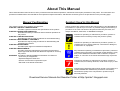
Symbols Used in this Manual
Various symbols are used throughout this manual either to provide additional
information on a specific topic or to warn of possible danger present during a
procedure or an action. Be aware of all symbols when they are used, and
always read NOTE, CAUTION, or WARNING messages.
Indicates an operating or maintenance procedure, practice or
condition that is necessary to keep the product’s quality.
Indicates an operating or maintenance procedure, practice, or
condition that, if not strictly observed, could result in damage to,
or destruction of, equipment.
May indicate an operating or maintenance procedure, practice or
condition that is necessary to accomplish a task efficiently. It may
also provide additional information that is related to a specific
subject, or comment on the results achieved through a previous
action.
Indicates an operating or maintenance procedure, practice or
condition that, if not strictly observed, could result in injury or loss
of life.
Indicates that a particular task must be carried out according to a
certain standard after disassembly and before re-assembly,
otherwise the quality of the components in question may be
adversely affected.
Download Service Manual And Resetter Printer at http://printer1.blogspot.com
Revision Status
Revision
Date of Issue
A
December 16, 2003
B
May 27, 2004
Description
First Release
Correction of the misspellings
Download Service Manual And Resetter Printer at http://printer1.blogspot.com
CONTENTS
Chapter 1 PRODUCT DESCRIPTION
1.1 Overview.................................................................................................. 9
3.1 Overview ............................................................................................... 38
3.1.1 Troubleshooting according to panel messages ............................ 38
3.1.2 Superficial Phenomenon-Based Troubleshooting ......................... 62
1.2 PG Setting ............................................................................................. 10
1.3 Functions .............................................................................................. 11
1.3.1 Control Panel ................................................................................ 11
1.3.2 Switches ........................................................................................ 11
1.3.3 Indicators ....................................................................................... 11
1.3.4 Switch Functions ........................................................................... 11
1.3.5 Indicator Display in Normal Mode ................................................. 12
1.3.6 Error Status ................................................................................... 13
Chapter 4 DISASSEMBLY & ASSEMBLY
1.4 Casing Specifications .......................................................................... 14
4.2 Disassembly ......................................................................................... 77
4.2.1 Removing the Housings ................................................................ 78
4.2.2 Stacker Assy. ................................................................................ 82
4.2.3 Waste Ink Pads ............................................................................. 84
4.2.4 ASF Assy. ..................................................................................... 86
4.2.5 Removing the Boards ................................................................... 90
4.2.6 Disassembling the Printer Mechanism .......................................... 96
4.2.7 Removing the Motors .................................................................. 130
4.2.8 Removing the Sensors ................................................................ 133
1.5 Accessories .......................................................................................... 14
Chapter 2 OPERATING PRINCIPLES
2.1 Overview................................................................................................ 16
2.2 Printer Mechanism ............................................................................... 16
2.2.1 Carriage Mechanism ..................................................................... 17
2.2.2 Printhead Specifications ................................................................ 20
2.2.3 Paper Feeding Mechanism ........................................................... 20
2.2.4 Paper Loading Mechanism ........................................................... 24
2.2.5 Ink System Mechanism ................................................................. 26
2.2.6 Ink Sequence ................................................................................ 28
2.2.7 Paper Cutter Mechanism .............................................................. 30
2.2.8 Power-On Sequence ..................................................................... 32
4.1 Overview ...............................................................................................
4.1.1 Precautions ...................................................................................
4.1.2 Tools to Be Used ..........................................................................
4.1.3 Screw List .....................................................................................
4.1.4 Pre-Shipment Checks ...................................................................
73
73
74
75
76
Chapter 5 ADJUSTMENT
5.1 Adjustment Items and Overview .......................................................
5.1.1 Servicing Adjustment Item List ....................................................
5.1.2 Replacement Part-Based Adjustment Priorities ..........................
5.1.3 Required Adjustment Jigs, Tools and Like ..................................
140
140
143
145
2.3 Electrical Circuitry Operating Principles............................................ 33
2.3.1 Power Supply Circuit Operating Principle ..................................... 33
2.3.2 C550 MAIN Circuit Operating Principle ......................................... 34
5.2 Adjustments........................................................................................ 145
5.2.1 PF Belt Tension Adjustment ....................................................... 145
5.2.2 PG Adjustment ............................................................................ 147
Chapter 3 TROUBLESHOOTING
Chapter 6 MAINTENANCE
Download Service Manual And Resetter Printer at http://printer1.blogspot.com
6.1 Overview.............................................................................................. 153
6.1.1 ROM Replacement ...................................................................... 153
6.1.2 Cleaning ...................................................................................... 153
6.1.3 Service Maintenance ................................................................... 154
6.1.4 Lubrication ................................................................................... 155
Chapter 7 APPENDIX
7.1 Connector Summary .......................................................................... 162
7.1.1 Connectors and Pin Layouts ....................................................... 162
7.2 Exploded Diagram .............................................................................. 163
7.3 Parts List for EPSON Stylus Photo R800 ......................................... 170
7.4 Component Layout............................................................................. 172
7.5 Circuit Diagram................................................................................... 174
Download Service Manual And Resetter Printer at http://printer1.blogspot.com
1
CHAPTER
PRODUCT DESCRIPTION
Download Service Manual And Resetter Printer at http://printer1.blogspot.com
EPSON Stylus Photo R800
Revision A
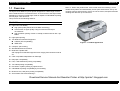
1.1 Overview
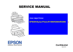
The Stylus Photo R800 is a photo printer designed for a wide range of users
from individual users to commercial users. As a successor to the Stylus Photo
950/960, this consumer middle high model is capable of CD-R/DVD-R printing
and roll paper cutter functions.
This product has the following features.
Note"*1": When user performs the "Auto nozzle check and cleaning", Prints
nozzle check pattern and automatically checks print head nozzles. If they are
clogged, performs head cleaning. If they are not recovered, and performs head
cleaning and detection up to tree times.
FEATURES
High Color Print Quality
High photo quality thanks to Photo Mach technology
Achievement of higher quality using microweaves and super
microweaves
High resolution printing of 5760 x 1440dpi, world's minimum dot 1.5pl
MSDT
High-speed printing
Two Different Interfaces Supported
USB 2.0 (HS compatibility)
IEEE-1394
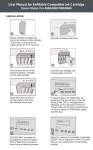
Figure 1-1. Product Appearance
Compact, space saving
Windows/Macintosh Exclusive
Multi-size Capable ASF
ASF equipped as standard supports forms ranging from business cards to
A4.
CSIC-compatible Independent Ink Cartridge
Roll paper compatibility
Fast, 4-side borderless printing compatibility
Two-sided printing compatibility
Prevention of platen printing by optical sensor
CD-R/DVD-R printing compatibility by front loading
Business card, card photo printing compatibility
Auto Nozzle Check and Cleaning*1
Download Service Manual And Resetter Printer at http://printer1.blogspot.com
PRODUCT DESCRIPTION
Overview
9
EPSON Stylus Photo R800
Revision A
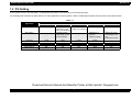
1.2 PG Setting
As this printer uses an Auto PG (APG), an appropriate PG position is set according to the used paper type.
The following table indicates the PG positions, the main applications of each position, and the relationships between the two sensors used with the APG.
Table 1-1.
Application
Printing
PG Position
PG (-)
• Special thick paper
Non-printing
–
PG (0)
PG (+)
PG (++)
• Plain paper
• Envelope
• CD-R/Board paper
• Special thin paper
• PG(0) rub avoidance
• PG(-) rub avoidance
• Standby position
after power-on (For
bottom stacker)
–
• Initialization at
power-on
• Cleaning (wiping)
Release
–
• Waiting for CD-R/
Board paper to be
fed
• Paper jam removal
PG value
1.2mm
1.7mm
2.1mm
4.5mm
–
Sensor
PG (-)
PG (Typ.)
PG (+)
PG (++)
Release
APG Sensor 1
OFF
OFF
OFF
OFF
OFF
APG Sensor 2
ON
ON
ON
OFF
OFF
Download Service Manual And Resetter Printer at http://printer1.blogspot.com
PRODUCT DESCRIPTION
PG Setting
10
EPSON Stylus Photo R800
Revision A
1.3 Functions
1.3.4 Switch Functions
1.3.1 Control Panel
FUNCTIONS IN NORMAL STATUS
Table 1-2. Normal-status Functions
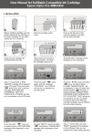
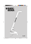
The appearance of the control panel is shown below.
Switch
Ink LED
Paper LED
Power LED
Roll paper switch
Power switch
• Power On/Off
Paper switch
• Loads or Ejects the Paper.
• In the condition of printing, cancel the print job.
Ink switch
• Starts the Cleaning of head with 3 second pushing.
• Moves the Carriage to ink cartridge change position.
• When Carriage is on the ink cartridge change position, return
carriage from ink cartridge change position.
Power switch
Ink switch
Paper switch
Function
Roll paper
switch
Figure 1-2. Control Panel Appearance
•
•
•
•
•
Loads the Roll paper.
Back out the roll paper with 3 second pushing.
Move to tear off position / Return from tear off position.
When the cutter is set, cuts the paper.
When the photo album is used, ejects the paper forwards only.
(At this mode, the printer can't move the cutter and can't move
backwards.)
Note : When the printer has frozen, hold down the Power switch and Ink switch for 7
seconds to forcibly switch power off.
1.3.2 Switches
Power switch
Paper switch
FUNCTION AT POWER-ON
Ink switch
Table 1-3. Power-on Function
Roll paper switch
Switch
Paper switch
1.3.3 Indicators
Power LED
: Green
Paper LED
: Red
Ink LED
: Red
Function
Starts status
printings.*1
Note "*1": Status printings prints firmware version, ink counter and nozzle check
patterns.
Download Service Manual And Resetter Printer at http://printer1.blogspot.com
PRODUCT DESCRIPTION
Functions
11
EPSON Stylus Photo R800
Revision A
1.3.5 Indicator Display in Normal Mode
Table 1-4. Printer Condition and LED Status
Printer status
Error status
Idle
Data Processing
Pause *1
Indicators
Power
Paper
Ink
Priority
–
On
–
–
20
–
Blink
–
–
19
Status 05h
–
–
–
18
Ink Sequence Processing
–
Blink
–
–
17
Ink Cartridge Change Mode
–
Blink
–
–
16
PG Release Processing
–
Blink
Blink
Blink
15
Ink Low (warning)
–
–
–
Blink
14
Tear Off Status
11h
–
Paper Mismatch Error
0Ch
–
–
13
Fast Blink
–
12
Paper Out
06h
–
On
–
11
Ink Out
05h
–
–
On
10
No Ink Cartridge or Ink Cartridge Error
05h
–
–
On
9
Paper Jam Error
04h
–
Blink
–
8
Card Loading Error
2Ah
–
Fast Blink
–
7
Cutter Jam Error
1Dh
–|
Blink 2
–
6
Cover Open Error
02h
–
Blink 2
Fast Blink
5
–
On
On
On
Å|
Fatal Error
00h
Off
Fast Blink
Fast Blink
4
Cutter Position Error
1Ch
Off
Blink 2
Blink 2
3
Maintenance Request
10h
Off
Blink
Alternately 1
Blink
Alternately 2
2
–
Fast Blink
Off
Off
1
Reset Input
Power Off
Note:
• "–"
• Blink
• Blink 2
• Fast Blink
• Blink alternately 1
• Blink alternately 2
: Don't care
: 0.5sec on + 0.5sec off repetition
: 0.2sec on + 0.2sec + 0.2sec on + 0.4sec off repetition
: 0.1sec on + 0.1sec off repetition
: 0.5sec on + 0.5sec off repetition
: 0.5sec off + 0.5sec on repetition
Note"*1": When the Photo album paper is end, the printer goes to this status.
Download Service Manual And Resetter Printer at http://printer1.blogspot.com
PRODUCT DESCRIPTION
Functions
12
EPSON Stylus Photo R800
Revision A
1.3.6 Error Status
Table 1-5. General error
If any of the following states is detected, this printer is put in an error status and
turns the interface signal -ERROR "Low" and BUSY "High" to inhibit data input.
At this time, the printer is automatically disabled from printing. However, when
communication is being made using the IEEE1284.4 protocol, communication
with the printer is enabled.
General error
After the cause of this type of error is removed, the printer can resume its
operation from where it stopped due to the error
Error Status
Occurring Condition
Resuming Condition
Cutter Jam Error
When Cutter can't cut the paper, it
goes Cutter Jam Error.
Switch power off and
recheck the cutter state.
When a paper jam has
occurred, clear the
paper.
Cover Open Error
When the cover is opened at
Economy printing mode, the printer
goes this error.
Close the cover.
Table 1-5. General error
Error Status
Paper Mismatch
Error
Paper Out
Ink Out
No Ink Cartridge/
CSIC Error
Paper Jam Error
Card Loading
Error
Occurring Condition
If the paper path specified by the
print data is different from the
printer's real paper path, the printer
goes to this error.
Resuming Condition
Change the printer's
paper path to the one
specified by the data.
Table 1-6. Fatal error
When printer fails to load a sheet, it
goes Paper Out Error.
Set the paper to the ASF
and push the Paper
switch.
When the printer runs out the most
part of the ink of any one color, it
warns Ink Low and keeps printing.
When the printer runs out the whole
ink of any one color, it stops printing
and indicates Ink Out Error. User is
requested to install a new InkCartridge in this state.
Install the new Ink
Cartridge.
When printer detects that Ink
Cartridge comes off, it goes this error
mode.
Install the new Ink
Cartridge.
• Failure of ejecting a sheet
• Failure of loading a sheet to the
loading position
When the card was loaded to the
wrong position, the printer goes this
error.
Fatal error
After the cause of this type of error is removed, the printer cannot return to
normal unless it is powered off and then on again
Error Status
Occurring Condition
Resuming Condition
Fatal Error
When detecting a Fatal Error such as
a carriage control error, the printer is
placed in an error status.
Turn off and turn on.
Cutter Position
Error
When Cutter can't return to cutter
home position, it goes Cutter Position
Error.
Switch power off and
recheck the cutter state.
When a paper jam has
occurred, clear the
paper.
Maintenance
Request
When the total quantity of ink wasted
through the cleaning and flushing is
reaches to the limit, printer indicates
this error and stops.
Replace the Waste Ink
Pads in the printer
enclosure by a service
person.
Remove the jammed
paper.
Set an A4 paper to the
ASF, and press the
Paper switch. If the card
couldn't eject at your first
try, repeat again the
same method.
Download Service Manual And Resetter Printer at http://printer1.blogspot.com
PRODUCT DESCRIPTION
Functions
13
EPSON Stylus Photo R800
Revision A
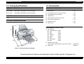
1.4 Casing Specifications
1.5 Accessories
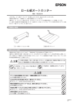
EXTERNAL DIMENSIONS
STANDARD ACCESSORIES
When tucked
: 495 (width) x 305 (depth) x 193 mm (height)
Setup guide
: 1 set
When used
: 495 (width) x 644 (depth) x 322 mm (height)
Ink Cartridge (one for each of 8 colors)
: 1 set
CD-ROM (Printer driver utility)
: 1 set
WEIGHT
CD/DVD tray
: 1 set
7.0kg
CD/DVD print position check sheet
: 1 set
8cm CD/DVD attachment
: 1 set
Roll paper holder
: 1 set
Power cord
: 1 set
EXTERNAL DIMENSION DIAGRAM
CONSUMABLES AND OPTIONS
Ink cartridges
322
193
305
644
495
Gloss Optimizer: T0540
Black
: T0541
Cyan
: T0542
Magenta
: T0543
Yellow
: T0544
Red
: T0547
Matte Black
: T0548
Blue
: T0549
Roll paper auto cutter
(Cutter, paper support basket, instruction manual)
: PMA4RAC3
USB cable
: USBCB2
Figure 1-3. External Dimension Diagram
Download Service Manual And Resetter Printer at http://printer1.blogspot.com
PRODUCT DESCRIPTION
Casing Specifications
14
2
CHAPTER
OPERATING PRINCIPLES
Download Service Manual And Resetter Printer at http://printer1.blogspot.com
EPSON Stylus Photo R800
Revision A
2.1 Overview
The basic structure of the mechanism has the following features.
This chapter explains the operating principles of the mechanical sections and
electrical circuits in this product. The main components of this product are as
follows.
Control circuit board
: C550 MAIN
Power supply circuit board
: C550 PSB/PSE
Control panel board
: C550 PNL
The sensor dedicated to Auto Bi-D adjustment and auto nozzle check is
installed.
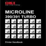
The following shows the outline of the printer mechanism.
PF Encoder
Sensor
PF Scale
Paper Eject
Roller (front)
PG Release
Sensor
2.2 Printer Mechanism
APG Sensors
PF Motor
Like the conventional model, this product uses DC motors as power sources.
The following table describes the motor types and their applications.
Paper Eject
Roller (rear)
APG Motor
Table 2-1. Various Motors
Motor Name
CR Motor
PF Motor
Type
PF Roller
Applications/Functions
DC motor with
brushes
Used for carriage driving. Makes little noise
during driving. The CR linear scale and CR
encoder sensor are used to control the motor.
DC motor with
brushes
Power source to drive the Paper loading rollers
at the time of fixed-value paper loading or paper
feed/eject operation. To grasp the paper feed
pitch, the precision gear surface is fitted with the
PF scale and the PF encoder sensor is used to
control the motor.
CR Encoder
Sensor
DC motor with
brushes
Power source to drive the Carriage Unit at the
time of PG setting. The two APG Sensors and
Carriage Shaft are driven vertically to control the
motor.
ASF Motor
4-phase, 48-pole
PM type
stepping motor
Performs the paper feed operation of the ASF.
Because of a stepping motor, this motor does
not require a scale, photo sensor and like to be
fitted to grasp the driving conditions.
Pump Motor
4-phase, 48-pole
PM type
stepping motor
Drives the pump, wiper, etc. of the Ink System.
Because of a stepping motor, this motor does
not require a scale, photo sensor and like to be
fitted to grasp the driving conditions.
APG Motor
Timing Belt
PW Sensor
LD Roller
Ink Mark
Sensor
Retard
Roller
Carriage
Unit
CR Scale
PE Sensor
Ink System
Unit
ASF Motor
Pump Motor
Carriage
Shaft
CR Motor
Figure 2-1. Printer Mechanism Outline
Download Service Manual And Resetter Printer at http://printer1.blogspot.com
OPERATING PRINCIPLES
Overview
16
EPSON Stylus Photo R800
Revision A
2.2.1 Carriage Mechanism
The Carriage mechanism consists of the Carriage Motor (CR Motor), Carriage
Shafts, Platen Gap Adjustment Mechanism, Carriage Lock Mechanism, and
others.
2.2.1.1 Carriage Mechanism
The following indicates the Carriage driving DC motor specifications.
The above control and sequences correct the drive current value of the CR
Motor according to not only the mechanical load but also the variations of the
motor and like. In addition, the resultant CR drive current value is used to
calculate a heating value, and when the specified heating value is reached,
wait time is provided per CR path for printing.
Table 2-2. CR Motor Specifications
Item
Specifications
Type
DC motor with brushes
Drive voltage
CR measurement sequence
To set the appropriate drive current value according to the variation of the
CR mechanical load, the mechanical load is measured in a CR
measurement sequence and saved into the EEPROM A4<H>, A5<H> in a
power-on or IC change sequence. However, if 46 is saved at the EEPROM
A4<H> and 05 at A5<H>, Fatal error will occur since too large load is
applied to the CR drive system.
+42V ± 5% (voltage applied to driver)
Winding resistance
24.4Ω ± 15%
Inductance
17.5mH ± 25%
Drive method
PWM, constant-current chopping
Drive IC
A6615
Closed loop control based on the CR Motor (DC Motor) and CR Encoder
Sensor has advantages in stabilized print quality and silent operation.
Heat generation control
Using low-cost DC motors, this product grasps the variations of the torque
constants, coil resistances and power supply board output voltages of the
individual DC motors adequately to carry out heat generation control
according to individual differences.
CR variation measurement sequence
The variations of the torque constant, coil resistance and power supply
board output voltage of the motor are measured in a CR variation
measurement sequence when the CR mechanical load is in the initial
status and saved into the EEPROM (A6<H>). According to the variations
(individual differences) measured in this sequence, the voltage is corrected
to make the drive current value constant (without an individual difference)
according to the variations (individual differences) measured in this
sequence.
Download Service Manual And Resetter Printer at http://printer1.blogspot.com
OPERATING PRINCIPLES
Printer Mechanism
17
EPSON Stylus Photo R800
Revision A
2.2.1.2 Carriage Home Position Detection
2.2.1.3 Sequence Used for PW Detection
As in the conventional model, the Carriage Home Position is detected using the
drive current of the CR Motor and the speed/position signal of the CR Linear
Encoder.
The basic home position detection sequence is as described below.
The PW (paper width detection) Sensor installed on the Carriage Unit bottom is
used to control the printer according to various sequences.
1. The CR linear encoder pulse counter in the CPU is reset by the
initialization operation performed at power-on.
2. When the CR Motor rotates counterclockwise, the Carriage Unit moves
from left to right. When the following conditions are satisfied, the CPU
assumes that the Carriage Unit made contact with the right frame.
The ASIC detects 862/1500 counts or more in the PWM output under
CR Motor load positioning control.
P1 (number of output pulses from when power is switched on until the
Carriage Unit makes contact with the right frame) is 12 steps or less.
3. When the CR Motor rotates clockwise, the Carriage Unit moves from right
to left. When the following conditions are satisfied, the CPU assumes that
the Carriage Unit reached the CR lock confirmation position.
The ASIC detects 483/1500 counts or more in the PWM output under
CR Motor load positioning control.
A difference between P1 and P2 (number of output pulses from when
the Carriage Unit made contact with the right frame until it reaches the
Carriage lock confirmation position) is 12 steps or less.
4. When the CR Motor rotates counterclockwise to move the Carriage from
left to right and the CPU detects 862/1500 counts or more in the PWM
output under CR Motor load positioning control, the printer judges it as
contact with the frame.
The following briefly describes the PW Sensor operating principle.
A dark voltage is measured by the PW Sensor in three places on the right end
plane (area without the absorber) of the Front Paper Guide every time power is
switched on, and the measurement values are saved into the EEPROM as
threshold values.
Threshold value > detection voltage: Paper present
Threshold value < detection voltage: Paper absent
The following sequences are performed.
Off-paper printing prevention control
Before start of printing (immediately after the end of paper locating), or
during printing, whether paper is present or not is detected to prevent offpaper printing on the Paper Guide by borderless printing used in a wrong
way. (This applies to only the left or right end of the paper.)
This control applies to only the four-side borderless mode.
CD-R center detection control
When printing is not being performed, the PW detector is used to detect
the center of CD-R. Refer to "2.2.3.4 CD-R Printing Mechanism (p.23)" for
details.
Board paper/roll paper leading edge detection control
Control exercised to detect the user-preset board paper leading edge, or
control carried out to detect the roll paper edge. Therefore, the PW sensor
does not detect a paper leading edge at the time of ASF cut sheet feeding.
5. When a difference between P1 and P3 (number of output pulses from
when the Carriage Unit reached the Carriage lock confirmation position
until it makes contact with the right frame) is 4 steps or less, the printer
judges that the Carriage Unit is in the home position.
The IC14 (ASIC) sets the drive current value adequate for the Carriage Unit
motion and outputs it to the motor driver.
Based on the signal output from the IC14 (ASIC), the IC5 (Motor Driver)
outputs the CR Motor drive current to the CR Motor.
Download Service Manual And Resetter Printer at http://printer1.blogspot.com
OPERATING PRINCIPLES
Printer Mechanism
18
EPSON Stylus Photo R800
Revision A
Off-range restriction control
At the time of frameless printing, a paper leading edge is detected using
the PW Sensor to restrict the frameless off-range amount.
Complete frameless mode
Control is performed to print the print data 3mm larger at top, 5mm
larger at bottom, and 2.5mm lager at left and right than the detected
paper size.
Roll paper mode
In the left and right frameless mode, control is performed to print the
print data 2.5mm lager at left and right than the detected paper size.
PW sensor dark voltage (VH) measurement
PW sensor dark voltage (VH) measurement is performed at the following
timings and locations and used to calculate the threshold value of whether
paper is present or not.
Cut sheets, Roll paper
The dark voltage is measured and updated at every power-on, and the
threshold value (VS) is calculated and saved in the EPROM area as a
PW detection level.
2.2.1.4 APG (Auto PG) Mechanism
The following indicates the APG DC motor specifications.
Table 2-3. APG Motor Specifications
Item
Specifications
Type
DC motor with brushes
Drive voltage
+42V ± 5% (voltage applied to driver)
Winding resistance
Inductance
Drive method
Drive IC
64.7Ω ± 15%
37.6mH ± 25%
PWM, constant-current chopping
A6615
The APG Motor (DC Motor) and two APG Sensors automatically adjust the PG
amount according to the paper.
APG Motor
• Threshold value > detection voltage: Paper present
• Threshold value < detection voltage: Paper absent
CD-R Tray
When a CD-R is used, the dark voltage is measured on the CD-R tray,
and the threshold value (VS) is then calculated and saved in the
EPROM area as a PW detection level.
PG Cam
• Threshold value > detection voltage: CD-R present
(tray home position detected)
The measurement voltage in the presence of the CD-R is saved into
the EEPROM as a white level. The white level value is used to check
the sensor deterioration condition during servicing or like.
• If the measurement value of the white level is close to that of the PW
detection level, it means that the sensor is dirty or deteriorated.
Carriage Shaft
Carriage Unit
Figure 2-2. APG Mechanism
Download Service Manual And Resetter Printer at http://printer1.blogspot.com
OPERATING PRINCIPLES
Printer Mechanism
19
EPSON Stylus Photo R800
Revision A
2.2.2 Printhead Specifications
2.2.3 Paper Feeding Mechanism
The Printhead of this product is a F-Mach head.
The following shows the arrangement of the nozzles and the color
arrangement of each nozzle line when they are viewed from behind.
The paper feeding mechanism indicates the mechanism that feeds paper or
CD-R Tray to the PF Roller Shaft.
7.620mm
7.620mm
7.620mm
(216/720inch) (216/720inch) (216/720inch)
2.258mm
2.258mm
2.258mm
2.258mm
(64/720inch) (64/720inch) (64/720inch) (64/720inch)
Cut sheet
Roll paper
PE Sensor
CD-R Tray
Star Wheel Rollers
Line A
Line C
Line B
Line E
Line D
Line G
Line F
Paper feeding
direction
Line H
Board Paper
0.141mm
(1/180inch)
0.071mm
(1/360inch)
Paper eject roller (front)
31.89mm
Paper eject roller (rear)
PF Roller
Figure 2-4. Paper Feeding Mechanism
41.66mm
Carriage moving direction
Figure 2-3. Nozzle Rear View
Table 2-4. Relationships between Nozzle Lines and Color Arrangement
Line
Ink
A
Yellow
B
Magenta
C
Cyan
D
Matte-black
E
Photo-black
F
Red
G
Blue
H
Gloss Optimizer
Download Service Manual And Resetter Printer at http://printer1.blogspot.com
OPERATING PRINCIPLES
Printer Mechanism
20
EPSON Stylus Photo R800
Revision A
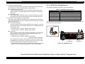
2.2.3.1 ASF Paper Feeding Mechanism
The following indicates the ASF Assy. driving stepping motor specifications.
1. When a paper feeding command is issued from the PC or the Paper Switch
of the panel is pressed after power-on, the driving force of the ASF Motor
begins to be transmitted to the LD Roller.
Table 2-5. ASF Motor Specifications
Item
Type
Specifications
4-phase, 48-pole PM type stepping motor
Drive voltage
Bipolar drive/constant-current drive
Winding resistance
+42V ± 5% (voltage applied to driver)
Inductance
7.4Ω ± 10% (per phase at 25°C)
Drive method
12.0mH ± 20% (1kH, 1Vrms)
Driven by the ASF Motor, the ASF Assy. performs the following feeding
operation.
2. The flag of the Paper Back Cam moves away from the home position of the
ASF Sensor and the LD Roller rotates.
3. When the LD Roller rotates one turn and the flag of the Paper Back Cam
returns to the home position of the ASF Sensor again, the LD Roller stops
rotating.
The drive of the ASF Motor is transmitted to the LD Roller in the following path.
LD Roller Drive Transmission Path
ASF Motor Pinion Gear ⇒ Combination Gear 29, 11 ⇒ Paper Back Cam
⇒ LD Roller
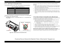
2.2.3.2 Manual Paper Feeding Mechanism (Board Paper)
To enable direct printing onto thick paper and CD-R label, this product has the
mechanism to feed paper from the printer front manually.
1. When the Stacker is lifted, the close signal of the PG Release Sensor is
transmitted to the APG Assy. in the following order.
ASF Motor
Paper Back Cam
PG Release Sensor ⇒ Main Board ⇒ Relay Board ⇒ APG Motor
⇒ APG Assy.
2. Driven by the APG Motor, the APG Assy. sets the PG position to PG
release to release the Upper Paper Guide (Driven Roller).
3. Along the Paper Feed Guide of the Stacker, match the leading edge (front
side) of the board paper to the marking position of the Stacker.
Combination Gear 29, 11
LD Roller Shaft
After the above operation, press the Paper Switch. When the PE Sensor
detects that the paper is present, it detects the leading edge of the paper, and
the printer performs paper locating and then enters the standby status.
Figure 2-5. LD Roller Drive Transmission Path
Download Service Manual And Resetter Printer at http://printer1.blogspot.com
OPERATING PRINCIPLES
Printer Mechanism
21
EPSON Stylus Photo R800
Revision A
When roll paper printing data is received (when cutter is not fitted)
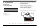
2.2.3.3 Roll Paper Feeding
Since panel operation in the roll paper mode differs from the above operation,
the differences of panel operation after roll paper feeding will be described.
1. When roll paper is fed, the PE Sensor detects the paper, and after 3
seconds have elapsed, the paper is fed.
2. The PW Sensor check for the leading edge of the paper, and if it detects
the paper, the printer operates in the Cutter Self-Cleaning Mode.
1. After end of printing, press the Roll Paper Switch.
2. A tear-off line is printed, and the roll paper is fed to the roll paper
cut position.
3. After cutting the roll paper with a pair of scissors or like, Press the
Roll Paper Switch. This returns the leading edge of the paper to
the print starting position.
3. The printer back-feeds the paper to the paper print starting position.
At this time, panel Switch operation is invalid, and the definitions of the panel
operation and Paper Switch differ between cut sheets and roll paper.
The following describes a difference between Panel Switch operations
performed when roll paper is fed and performed when roll paper printing data is
received from the PC.
When roll paper is fed
Pressing the Roll Paper Switch for more than 3 seconds back-feeds the
leading edge of the roll paper to the PE Sensor (the Paper LED blinks). In
this state, draw the roll paper and press the Paper Switch to return to the
panel operation that enables paper feeding from the ASF.
When roll paper printing data is received (when cutter is fitted)
When data is "No auto cut"
1. After end of printing, press the Roll Paper Switch. This feeds the
separation position in the print data to the roll paper cut position.
2. After the paper is cut, the leading edge of the paper returns to the
print starting position.
When data is "Standard 1 cut" or "Specific 2 cuts"
1. The roll paper is cut automatically at every separation of the print
data.
2. After the paper is cut, the leading edge of the paper returns to the
print starting position.
Download Service Manual And Resetter Printer at http://printer1.blogspot.com
OPERATING PRINCIPLES
Printer Mechanism
22
EPSON Stylus Photo R800
Revision A
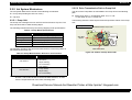
2.2.3.4 CD-R Printing Mechanism
CD-R tray home position detection sequence
Lift the Stacker (PG Release Sensor: Close), insert the CD-R Tray into the
specified position, and press the Paper Switch. This starts the following
operation.
When the close signal of the PG Release Sensor is detected, no paper is
fed from the ASF if the Paper Switch is pressed. In this case, the Paper
Switch executes a CD-R Tray home position detection sequence.
9. The Carriage Unit moves to the CD-R Tray HP detectable position
and stops there, and then the CD-R Tray is fed in the ASF
direction.
10. When the CD-R Tray stops operating, the Carriage Unit moves to
the carriage HP and stands by.
If the CD-R Tray HP, white marking or CD-R cannot be detected in any
specified step operation in the CD-R Tray HP detection sequence, the CD-R
Tray is ejected and Paper Out Error is displayed.
1. When the APG Assy. is driven, the PG position is set to "++" and
the Driven Roller of the Upper Paper Guide presses the CD-R
Tray.
PW Sensor
2. When the Carriage Unit moves leftward and the PW Sensor
detects the CD-R, the Carriage Unit returns to the carriage home
position (HP).
3. After waiting for about 5 seconds at the carriage HP, the Carriage
Unit moves to the CD-R Tray HP detectable position (right end of
the CD-R Tray).
4. The CD-R Tray is pulled in the ASF direction, the PW Sensor
detects the CD-R Tray HP, and then the Carriage Unit moves to
the center of the CD-R Tray.
5. When the PW Sensor detects the white marking in the center of
the CD-R Tray, the CD-R Tray is fed in the paper ejection
direction.
6. The Carriage Unit moves leftward, the PW Sensor detects the left
side white marking, then the Carriage Unit moves rightward, and
the PW Sensor detects the right side white marking.
Carriage Unit
CD-R Tray
CD-R home position
Figure 2-6. CD-R Printing Mechanism
7. The Carriage Unit moves to the center of the CD-R Tray, and the
PW Sensor starts detection in the back-and-forth direction of the
CD-R. After the leading edge of the CD-R is detected, the CD-R
Tray is fed in the paper ejection direction, and the trailing edge of
the CD-R is detected. After that, the CD-R Tray is fed to the center
of the CD-R in the paper ejection direction.
8. The Carriage Unit moves leftward, and the PW Sensor starts
detection in the horizontal direction of the CD-R. After the left end
of the CD-R is detected, the Carriage Unit moves rightward, and
the right end of the CD-R is detected.
Download Service Manual And Resetter Printer at http://printer1.blogspot.com
OPERATING PRINCIPLES
Printer Mechanism
23
EPSON Stylus Photo R800
Revision A
2.2.4 Paper Loading Mechanism
The Paper Loading Mechanism is designed to transfer the paper fed from the
ASF, Roll Paper Guide or Board Paper Guide or the CD-R fed from the CD-R
Tray according to the print data.
2.2.4.1 Paper Loading Mechanism
The following indicates the paper loading driving DC motor specifications.
Table 2-6. PF Motor Specifications
Item
DC motor with brushes
Drive voltage
+42V ± 5% (voltage applied to driver)
Winding resistance
22.3Ω ± 25%
Inductance
17.3mH ± 25%
Drive method
PWM
Drive IC
A6615
PF Roller Drive Transmission Path
PF Motor Pinion Gear ⇒ PF Timing Belt ⇒
Combination Gear 36.294, 45.5 ⇒ PF Roller Shaft
Paper Eject Roller (front) Drive Transmission Path
PF Motor Pinion Gear ⇒ PF Timing Belt ⇒
Combination Gear 36.294, 45.5 ⇒ Spur 31.5 ⇒ Spur 54 ⇒
Paper Eject Roller (front)
Paper Eject Roller (rear) Drive Transmission Path
PF Motor Pinion Gear ⇒ PF Timing Belt ⇒
Combination Gear 36.294, 45.5 ⇒ Spur 31.5 ⇒ Spur 54 ⇒ Spur 18 ⇒
Spur 15.5 ⇒ Spur 18 ⇒ Paper Eject Roller (rear)
Specifications
Type
The driving force of the PF Motor is transmitted to the PF Roller and Paper
Eject Roller in the following path.
The following shows the part names and outline of the drive transmission path.
Paper is transferred in the above driving force transmission path.
Like the CR Motor, a DC motor is used as the PF Motor in this product.
Closed loop control based on the DC Motor and Rotary Encoder has the
following advantages.
Combination Gear
36.294, 45.5
Spur 54
Spur 18
PF Timing Belt
Spur 18
Improved paper feed accuracy
Paper feed amount control
Pinion Gear
Spur 31.5
PF Motor
PF Roller
Spur 15.5
Front Paper
Guide
Paper Eject
Roller (front)
Paper Eject
Roller (rear)
Figure 2-7. Paper Loading Mechanism 1
Download Service Manual And Resetter Printer at http://printer1.blogspot.com
OPERATING PRINCIPLES
Printer Mechanism
24
EPSON Stylus Photo R800
Revision A
The fed paper is detected by the PE Sensor, and its leading edge is then
transferred to the front of the Front Paper Guide.
To eliminate the deflection of the paper, the paper is then returned toward the
ASF Assy. by the specified number of steps according to the paper feed mode.
The paper is transferred again to the specified paper locating position of the
Front Paper Guide.
Print Head
Paper
Driven Roller
2.2.4.2 PF Measurement Sequence
The mechanical load in the paper loading path is measured in the following
cases to perform control so that an adequate current value is set according
to the mechanical load.
When power is switched on
When the Ink Cartridge is replaced
When the removal or fitting of the cutter is recognized in the paper feed
sequence
When the mechanical load in the paper loading path reaches the specified
value, Fatal Error is displayed. (When the cutter is not fitted)
Star Wheel Rollers
When the cutter is fitted, the mechanical load when the cutter is fitted is
measured and reflected on the control since the mechanical load of the
cutter must be taken into consideration to set the adequate current value.
Paper eject roller (front)
Paper eject roller (rear)
PF Roller
Figure 2-8. Paper Loading Mechanism 2
Download Service Manual And Resetter Printer at http://printer1.blogspot.com
OPERATING PRINCIPLES
Printer Mechanism
25
EPSON Stylus Photo R800
Revision A
2.2.5 Ink System Mechanism
2.2.5.2 Drive Transmission Path to Pump Unit
The Ink System Mechanism consists of the following mechanisms.
The drive of the Pump Motor is transmitted to the Pump Unit in the following
path.
Pump Unit (including the CR Lock Lever)
Motor Pinion Gear ⇒ Combination Gear 10.2, 21.2 IS
⇒ Spur Gear 20.4 IS ⇒ Pump Unit
Cap Unit
2.2.5.1 Pump Unit
The Pump Unit is designed to suck ink from the Print Head or Cap Unit. The
Cap Unit has a built-in Head Cleaning Wiper.
The following shows the internal part names and operation outline of the Pump
Unit.
<Pump Unit inside>
The following indicates the Pump Unit driving stepping motor specifications.
Combination Gear 10.2, 21.2 IS
Table 2-7. Pump Motor Specifications
Item
Specifications
Type
4-phase, 48-pole PM type stepping motor
Drive voltage
Bipolar drive/constant-current drive
Winding resistance
+42V ± 5% (voltage applied to driver)
Inductance
10.3Ω ± 10% (per phase at 25°C)
Drive method
13.4mH ± 20% (1kH, 1Vrms)
Spur Gear
20.4 IS
The following operations are performed when the drive of the Pump Motor is
transmitted to the Pump Unit.
Motor Pinion Gear
Figure 2-9. Outline of Pump Unit Inside
Table 2-8. Pump Motor Rotation Directions and Functions
Pump Motor Rotation Direction*
Functions
CW direction
•
•
•
•
Cap closing
Ink suction
Wiper resetting
CR Lock setting
CCW direction
•
•
•
•
Cap opening
Pump release
Wiper setting
CR Lock resetting
Note: As the rotation directions of the motor, CW indicates a clockwise
direction, and CCW indicates a counterclockwise direction, as seen
from the output shaft side of the motor mounting plate.
Download Service Manual And Resetter Printer at http://printer1.blogspot.com
OPERATING PRINCIPLES
Printer Mechanism
26
EPSON Stylus Photo R800
Revision A
2.2.5.3 Cap Unit
The following shows the Pump Unit operating principle.
The Cap Unit is designed to bring the Cap into close contact with the Print
Head surface and suck ink by the driving force of the Pump Unit to secure air
tightness in the Cap.
Cap Unit Side
When the printer is in a standby status or its power is OFF, the Cap Unit
prevents the ink from thickening.
Ink is fed to the Waste Ink Pad in the following path.
Ink Cartridge ⇒ Head Cavity ⇒ Cap ⇒ Waste Ink Pad
The following diagram shows the outline of Cap Unit operation.
To Waste ink pad
Carriage Unit
Figure 2-10. Pump Unit Operating Principle
Cap
Ink suction
1. The Pinion Gear of the Pump Motor rotates in the CW direction.
2. The Roller turns and simultaneously presses the tube.
3. Ink is fed from the Cap Unit toward the Waste Ink Pad.
Print Head
Pump release
1. The Pinion Gear of the Pump Motor rotates in the CCW direction.
Slider cap rises to perform
capping.
Figure 2-11. Capping Mechanism
2. The Roller moves away from the tube and releases the tube.
3. Ink is not sucked.
Download Service Manual And Resetter Printer at http://printer1.blogspot.com
OPERATING PRINCIPLES
Printer Mechanism
27
EPSON Stylus Photo R800
Revision A
2.2.6 Ink Sequence
The following ink sequence is executed according to various timer, counter,
flag and other information saved on the EEPROM.
CSIC-related sequence
The ink type code stored in the CSIC Memory Chip is identical regardless
of the Japanese domestic or overseas cartridges, and is saved at the Main
Board EEPROM.
At power-on, data is read from each color CSIC and the CSIC data status
is made valid. If the data read from each CSIC has any problem, Ink
cartridge error or Ink end error is displayed.
After CSIC operation is checked, the ink consumption of the I/C currently
installed per color is compared with the ink consumption saved in the
printer EEPROM, and control is performed under the following conditions.
When current I/C consumption differs (from ink consumption in
EEPROM)
1. On the assumption that the I/C has been changed at power-off, the
first I/C flag is reset.
2. The installation count in the printer EEPROM is updated for the
CSIC. In the CSIC information replacement sequence, the CSIC
side ink consumption data is updated to the ink consumption data
in the printer EEPROM.
3. The used model name data on the I/C side is rewritten.
Note: Reason why the used model name data is rewritten from the
printer to the I/C: To grasp which printer used the I/C removed.
When current I/C consumption is the same (as ink consumption in
EEPROM)
1. When the initial filling flag is set and the CSIC side ink
consumption is 0, the printer judges that initial filling is not yet
performed.
(The printer before initial filling judges that the I/C is fitted in a
power-off status.)
2. Installation count updating, CSIC information replacement, and
initial filling are executed in this order.
3. If the initial filling flag is not set, the printer judges that I/C change
was not made at power-off and regards the CSIC data as valid.
Data is written to the CSIC at the following timings.
At power-off
In the power saving mode
At the time of Ink Cartridge replacement
At the time of cleaning
1. Data is read from the CSIC and developed in the RAM on the Main
Board.
2. The data is compared with the ink consumption in the printer
EEPROM. If the data are the same, the data is written to the CSIC.
If they are different, only the consumed difference is added and
written to the CSIC. When cleaning is performed, the CL count is
also written, and when the I/C is changed, the installation count is
also written.
4. The change flag 2 (flag that indicates change CL) is set and CL is
executed.
Download Service Manual And Resetter Printer at http://printer1.blogspot.com
OPERATING PRINCIPLES
Printer Mechanism
28
EPSON Stylus Photo R800
Revision A
Initial ink filling
When the printer is powered on for the first time after the purchase of the
product, the printer executes the initial ink filling operation to fill the ink
cavities of the Head with ink. When the initial ink filling operation is
performed properly, the printer clears the flag in the EEPROM so that initial
ink filling operation will not be performed when it is powered on next. The
Stylus Photo R800 requires about 150 seconds to perform the initial ink
filling operation and consumes about 1/ 7 of the new ink cartridge.
If the sequence does not end normally during initial filling, the initial filling
flag is not cleared and the CL operating flag is set. Because of these flags,
when powered on next time, the printer assumes that it was powered off for
some reason during initial filling and executes CL3 instead of the initial
filling sequence. (On the conventional mode, initial filling was executed
again. However, when this operation was performed, ink was wasted and
therefore CL3 is executed to cover the ink filling performance.)
When the initial filling flag is set and the CL operating flag is not set, the
printer assumes that the initial filling was not executed at all (power was
switched on but the cartridges were not set), and when the printer is
powered on next time, it executes initial filling.
Manual cleaning
This product provides three different manual cleanings to remove ink
coagulated by air bubbles, viscous material or foreign matter. Perform the
following manual CL operations by operating the panel or using the utility
included in the printer driver.
Independently of the printing path after the previous CL, perform manual
CL from CL1 to CL3 in order if the cumulative printing timer counter is less
than 7min. Only when the cumulative printing timer counter is more than
7min, execute only CL1.
CL1: 1.704g (0.213g per color)
CL2: 4.488g (0.561g per color)
CL3: 7.120g (0.890g per color)
Wiper operation
Clean the nozzle surface with the right-half rubber part of the wiper.
Flushing operation
Prevent color mixture. Stabilize the ink surface inside the nozzles.
If the remaining ink amount of the I/C is short or the I/C is in an Ink Low/Out
status, all manual cleanings are disabled and STM3 shows the condition.
Change cleaning
Change CL1 is executed when Ink Cartridge change is made.
Change CL1: 3.4g (0.425g per color)
Download Service Manual And Resetter Printer at http://printer1.blogspot.com
OPERATING PRINCIPLES
Printer Mechanism
29
EPSON Stylus Photo R800
Revision A
Timer cleaning
Ink is consumed depending on the combination of the cumulative printing
timer, cumulative cleaning count and cleaning timer.
Flushing
Two different flushing operations are executed for the following reasons.
Periodic flushing
This is done to prevent ink viscosity in the Print Head nozzles from
increasing during continuous printing. A specific small amount of ink is
discharged into the Cap according to the Periodic flushing timer.
Periodic large-amount flushing
This is done to prevent ink viscosity in the Print Head nozzles from
increasing during continuous printing. A large amount of ink is
discharged into the Cap according to the Periodic large-amount
flushing timer.
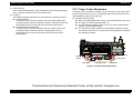
2.2.7 Paper Cutter Mechanism
The Paper cutter mechanism consists of such main parts as the Cutter Motor,
left and right HP Sensors (2 pcs. in all), Relay Board, Paper Eject Roller and
Paper Holddown Flap in the Cutter unit.
Operation during printing
When the Cutter Blade starts cutting, the Paper Hold-down Flap rises.
The paper is held and simultaneously cut.
The HP Sensors installed on both ends of the Cutter operating area
detect the Cutter Blade position.
The HP Sensors detect whether the Cutter Blade operates properly,
and Cutter Position Error or Cutter Jam Error is displayed according to
the operating condition.
Paper Holddown Flap
Right HP Sensor
Left HP
Sensor
Cutter Blade
Cutter Motor
Paper Eject Roller
Relay Board
Figure 2-12. Paper Cutter Mechanism
Download Service Manual And Resetter Printer at http://printer1.blogspot.com
OPERATING PRINCIPLES
Printer Mechanism
30
EPSON Stylus Photo R800
Revision A
2.2.7.1 Cutter Initialization Sequence
Paper cutting by the Cutter consists of the basic cutting sequences 1 and 2.
When the Cutter is fitted, the Cutter initialization sequence is executed if the
printer has confirmed that the Cutter has been fitted (the Power Switch blinks
about 5 seconds).
Basic cutting sequences 1
Means movement from the right HP Sensor to the left HP Sensor. At this
time, as soon as the Cutter Blade starts moving from the right HP Sensor,
the Timer starts. If the left HP Sensor does not detect the Cutter Blade
within 3 seconds, the Cutter initialization sequence is executed and then
Cutter Jam Error or Cutter Position Error occurs.
Cutter Initialization Sequence
The initialization sequence is performed to securely put the Cutter Blade in
a standby position detected by the right HP Sensor if the Cutter Blade is
not detected by the right HP Sensor.
The initialization operation is not performed if the Cutter Blade is in the
right HP Sensor position when the Cutter is fitted.
During Cutter operation, Cutter Position Error or Cutter Jam Error may occur.
These errors are explained below.
If the Cutter Blade cannot reach the left or right HP Sensor, the Cutter
Blade is returned to the HP Sensor located in the motion starting position
(right HP Sensor).
Cutter Jam Error
Indicates that the Cutter Blade can return to the HP Sensor position in
the motion starting position within 3 seconds.
Cutter Position Error
Indicates that the Cutter Blade cannot return to the HP Sensor position
located in the motion starting position within 3 seconds.
Basic cutting sequences 2
Means movement from the left HP Sensor to the right HP Sensor. At this
time, if the Cutter Blade cannot move from the left HP Sensor to the right
HP Sensor within 3 seconds, Cutter Position Error occurs.
2.2.7.2 Cutter Self-cleaning
This sequence indicates the operation performed to hold down and remove the
ink, which may stick to the Plate above the Paper Hold-down Flap (Plate where
the paper print surface comes into contact), with the leading edge of the fed roll
paper.
The Cutter Blade must be operated left-to-right to operate the Paper Holddown Flap. At this time, the Cutter Blade generates operating noise during
Cutter self-cleaning when the roll paper is fed.
2.2.7.3 Cutter Cleaning (Driver Side)
This sequence is executed on the driver side. By cutting the roll paper three
times at intervals of 7cm, the ink that may stick to the Cutter Blade is removed
to clean the Cutter Blade.
Download Service Manual And Resetter Printer at http://printer1.blogspot.com
OPERATING PRINCIPLES
Printer Mechanism
31
EPSON Stylus Photo R800
Revision A
2.2.8 Power-On Sequence
CARRIAGE UNIT OUTSIDE HP
The following explains the operation to be performed when the Carriage Unit is
inside or outside the HP with the printer powered on.
CARRIAGE UNIT INSIDE HP (CR LOCKED)
1. After power-on, the drive of the APG Motor is transmitted to the Carriage
Shaft, and the PG position changes from PG Typ. to PG++.
2. The drive of the CR Motor is transmitted to the Carriage Unit, and the
Carriage Unit performs HP detection operation in the following path.
Home position ⇒ Right frame ⇒ CR Lock confirmation position
⇒ Right frame ⇒ Home position
3. The drive of the Pump Motor is transmitted to the Cap Unit, the Cap opens
(lowers), and the CR Lock is released.
4. After the Carriage Unit has moved leftward by the specified number of
steps, the Wiper is driven by the Pump Motor to perform the following
operation, and during that period, ink is sucked for about 4 seconds.
1. When the PG position is other than PG++ after power-on, the drive of the
APG Motor is transmitted to the Carriage Shaft, and the PG position
changes to PG++.
2. The drive of the CR Motor is transmitted to the Carriage Unit, and the
Carriage Unit returns to the home position at slow speed.
3. The drive of the PF Motor is transmitted to the PF Roller and Paper Eject
Rollers (front and rear), which then rotate for about 2 seconds.
4. After the Carriage Unit has moved leftward by the specified number of
steps, the Wiper is set, driven by the Pump.
5. After the Carriage Unit has returned to the home position, it moves leftward
again by the specified number of steps. And, driven by the Pump Motor, ink
is sucked for about 4 seconds and then the Wiper is set, and the CR Lock
is placed.
6. The Carriage Unit performs HP detection operation in the following path.
Wiper setting ⇒ Wiper resetting
Home position ⇒ Right frame ⇒ CR Lock confirmation position
⇒ Right frame ⇒ Home position
5. The Carriage Unit returns to the home position, and the PG position
returns from PG++ to PG Typ.
7. The drive of the Pump Motor is transmitted to the Cap Unit, the Cap opens
(lowers), and the CR Lock is released.
6. The drive of the PF Motor is transmitted to the PF Roller and Paper Eject
Rollers (front and rear), which then rotate for about 2 seconds.
8. The Carriage Unit returns to the home position, and the PG position
returns from PG++ to PG Type.
7. After moving between the left and right frames twice, the Carriage Unit
moves to the right end of the Front Paper Guide.
9. The drive of the PF Motor is transmitted to the PF Roller and Paper Eject
Rollers (front and rear), which then rotate and stop as described below.
8. The PF Roller and Paper Eject Rollers (front and rear) rotate.
Rotation for about 4 seconds (slow speed) ⇒ Rotation for about 2
seconds
9. The Carriage Unit returns to the home position and is fixed by the CR Lock.
Rotation for about 3 seconds ⇒ Stop for about 0.5 seconds ⇒
Rotation for about 2 seconds
10. As soon as the operation in step 9 starts, the drive of the ASF Motor is
transmitted to the LD Roller, and the LD Roller rotates one turn.
11. The operations in Steps 7 to 9 of "Carriage Unit inside HP (CR locked)
(p32)" are performed, and the Carriage Unit is locked.
Download Service Manual And Resetter Printer at http://printer1.blogspot.com
OPERATING PRINCIPLES
Printer Mechanism
32
EPSON Stylus Photo R800
Revision A
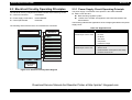
2.3 Electrical Circuitry Operating Principles
The electrical circuitry of Stylus Photo R800 consists of the following circuits.
Control circuit board
: C550 MAIN
Power supply circuit board : C550 PSB/PSE
Control panel board
: C550 PNL
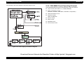
The following shows how the three circuit boards are connected.
2.3.1 Power Supply Circuit Operating Principle
The power supply circuit board of this product is the C550 PSB/PSE.
Basic circuit structure
RCC switching regulator system
+42VDC and +3.3VDC are supplied to the Printer Mechanism and
Control Board
The following indicates the applications of the voltages generated in this power
supply circuit.
Table 2-9. Supplied Power
Printer
Mechanism
PNL Board
Voltage
•
•
•
•
•
•
CR Motor
PF Motor
PG Motor
ASF Motor
Pump Motor
Head drive voltage
+3.3VDC
Rated output current: 0.5A
•
•
•
•
Logic sensor circuit
Sensor circuit
Nozzle selection circuit (above Print Head)
Interface control circuit
CR Motor
PF Motor
APG Motor
ASF Motor
MAIN Board
Applications
+42VDC
Rated output current: 0.45A
Pump Motor
Head drive circuit
Sensors
Power OFF
+3.3VDC
+42VDC
PSB/PSE
Power Supply
Board
Figure 2-13. Electrical Circuitry Block Diagram
Download Service Manual And Resetter Printer at http://printer1.blogspot.com
OPERATING PRINCIPLES
Electrical Circuitry Operating Principles
33
EPSON Stylus Photo R800
Revision A
The following is the block diagram of the power supply circuit.
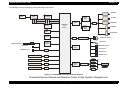
2.3.2 C550 MAIN Circuit Operating Principle
The C550 MAIN Board consists of the following circuits and sensors.
Logic Circuits (CPU-ASIC 2 in 1, PROM, SDRAM)
Motor control/Drive circuits
(CR Motor, PF Motor, APG Motor, ASF Motor, Pump Motor)
Head control/Drive circuit
Interface Circuits
USB 2.0, IEEE1394
Sensor circuits
Reset circuits
EEPROM circuit
D/A converter circuit
Figure 2-14. Power Supply Circuit Block Diagram
Download Service Manual And Resetter Printer at http://printer1.blogspot.com
OPERATING PRINCIPLES
Electrical Circuitry Operating Principles
34
EPSON Stylus Photo R800
Revision A
The following indicates differences between the control circuits of this product
and conventional model.
Adoption of 1.5V drive logic circuit components
The 1.5V voltage is generated by the Regulator IC installed on the C550
MAIN Board that reduces +3.3VDC generated by the C550 PSB/PSE
Board, and is used to drive multiple components.
This is done to reduce the power of the logic circuit.
The following table indicates the 3.3V drive components and 1.5V drive
components.
Table 2-10. 3.3V and 1.5V Drive Components
3.3V
1.5V
• Nozzle selection circuit
(above Print Head)
• CR Encoder Sensor
• PE Sensor
• PG Release Sensor
• CSIC
•
•
•
•
•
•
•
•
CPU-ASIC 2 in 1
PROM
SDRAM
Motor circuit
Panel LED
Interface circuit
USB 2.0
Sensors
(other than CR Encoder Sensor, PE
Sensor, PG Release Sensor)
Download Service Manual And Resetter Printer at http://printer1.blogspot.com
OPERATING PRINCIPLES
Electrical Circuitry Operating Principles
35
EPSON Stylus Photo R800
Revision A
The following is the block diagram of the C550 MAIN control board.
CR Motor
IEEE 1394
(IC1)
IEEE 1394
CN3
PROM
(IC4, IC15)
Motor
Driver
(IC5)
Data
Address
SDRAM
(IC12)
DAC
(IC2)
PF Motor
APG Motor
CN4
CPU-ASIC
2 in 1
(IC14)
Motor
Driver
(IC6)
ASF Motor
USB
CN2
Pump Motor
Reset
(IC13)
CN5
Relay Board
PF Encoder Sensor
PE Sensor
Reset
(IC16)
CR Encoder Sensor
PW Sensor
PG Release Sensor
EEPROM
(IC3)
ASF Sensor
Ink Mark Sensor
CN4
APG Sensor 1
C550 PSB/PSE Board
CN7
C550 Panel Board
CN8
CSIC Board
CN10
Cutter Unit
APG Sensor 2
CN11
Head
Driver
(IC7)
CN12
Q13, Q14
CN6
CN13
CN14
Print Head
Figure 2-15. C550 MAIN Control Board Block Diagram
Download Service Manual And Resetter Printer at http://printer1.blogspot.com
OPERATING PRINCIPLES
Electrical Circuitry Operating Principles
36
3
CHAPTER
TROUBLESHOOTING
Download Service Manual And Resetter Printer at http://printer1.blogspot.com
EPSON Stylus Photo R800
Revision A
3.1 Overview
This chapter describes unit-level troubleshooting.
3.1.1 Troubleshooting according to panel messages
After checking the printer LED and EPW3 error indications, you can grasp the fault location using the check list in this section. When you have found the fault
location, refer to Chapter 4 "Disassembly and Reassembly" and change the corresponding part and/or unit. The following table indicates the check point reference
tables corresponding to the error states (LED and EPW3).
Table 3-1. Reference Tables of Error States
Error State
Reference Table
Communication Error
Refer to Table 3-2 "Phenomenon-Based Communication Error Check Points" on page 39
Model Difference
Refer to Table 3-2 "Phenomenon-Based Communication Error Check Points" on page 39
Cover Open Error
Refer to Table 3-3 "Phenomenon-Based Cover Open Error Check Points" on page 42
Paper Out Error
Refer to Table 3-4 "Phenomenon-Based Paper Out Error Check Points" on page 43
Paper Jam Error
Refer to Table 3-5 "Phenomenon-Based Paper Jam Error Check Points" on page 48
Card Loading Error
Paper Mismatch Error
Ink Low
Ink Out Error
No Ink Cartridge/CSIC Error
Cutter Jam Error
Cutter Position Error
Maintenance Request
Fatal Error
Refer to Table 3-6 "Phenomenon-Based Card Loading Error Check Points" on page 49
Refer to Table 3-7 "Phenomenon-Based Paper Mismatch Error Check Points" on page 50
Refer to Table 3-8 "Phenomenon-Based Ink Low Check Points" on page 50
Refer to Table 3-9 "Phenomenon-Based Ink Out Error Check Points" on page 50
Refer to Table 3-10 "Phenomenon-Based No Ink Cartridge/Ink Cartridge Error Check Points" on page 51
Refer to Table 3-11 "Phenomenon-Based Cutter Jam Error Check Points" on page 53
Refer to Table 3-12 "Phenomenon-Based Cutter Position Error Check Points" on page 54
Refer to Table 3-13 "Phenomenon-Based Maintenance Request Check Points" on page 55
Refer to Table 3-14 "Phenomenon-Based Fatal Error Check Points" on page 56
Download Service Manual And Resetter Printer at http://printer1.blogspot.com
TROUBLESHOOTING
Overview
38
EPSON Stylus Photo R800
Revision A
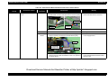
Table 3-2. Phenomenon-Based Communication Error Check Points
Occurrence
Timing
At power-on
Phenomenon Detail
The printer does not operate
at all.
Faulty Part/
Part Name
Panel FFC
Check Point
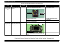
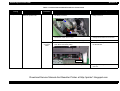
Remedy
1. Check that the Panel FFC is securely connected to the
Panel Board connector and Main Board connector (CN8).
1. Connect the Panel FFC to the Panel
Board and Main Board connectors.
Panel FFC
Panel FFC
Main Board
connector
Panel Board
Power Supply
Board
Panel Board
connector
2. Check the Panel FFC for damage.
2. Change the Panel FFC for a new one.
1. Check the Panel Board for damage.
1. Change the Panel Board for a new one.
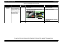
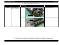
1. Check that the Connector cable of the Power Supply
Board is securely connected to the Main Board (CN7).
1. Connect the Connector cable of the
Power Supply Board.
Blue line
Connector cable
of the Power
Supply Board
1Pin side
2. Check that the blue line side pin of the Power Supply
2. Match and connect the blue line of the
Board Connector cable is inserted into the 1 Pin. (Refer to
Power Supply Board Connector cable
the above photo.)
into the 1 Pin.
Download Service Manual And Resetter Printer at http://printer1.blogspot.com
TROUBLESHOOTING
Overview
39
EPSON Stylus Photo R800
Revision A
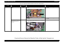
Table 3-2. Phenomenon-Based Communication Error Check Points
Occurrence
Timing
At power-on
Phenomenon Detail
Faulty Part/
Part Name
The printer does not operate
at all.
Power Supply
Board
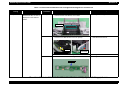
Check Point
Remedy
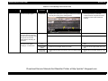
3. Check that the Fuse (F1) on the Power Supply Board is not 3. Change the Power Supply Board for a
blown.
new one.
Fuse (F1)
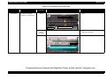
After the power-on sequence
has started, the LED turns off
and the printer does not
operate.
Main Board
4. Check the devices on the Power Supply Board for
damage.
4. Change the Power Supply Board for a
new one.
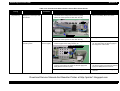
1. Check that the Relay connector of the ASF Motor and the
Relay connector of the Pump Motor are not connected to
cause a short circuit.
1. Change the Main Board for a new one.
Relay Connector
of the ASF Motor
Relay Connector
of the Pump Motor
Download Service Manual And Resetter Printer at http://printer1.blogspot.com
TROUBLESHOOTING
Overview
40
EPSON Stylus Photo R800
Revision A
Table 3-2. Phenomenon-Based Communication Error Check Points
Occurrence
Timing
At operation
Phenomenon Detail
Operation at power-on is
normal, but the error appears
when the print jog is sent to
the printer.
Faulty Part/
Part Name
Check Point
Remedy
Interface cable 1. Check that the Interface cable is connected between the
PC and printer.
1. Connect the Interface cable to the PC
and printer.
2. Check the Interface cable for wire break.
2. Change the Interface cable for a new
one.
EPSON
USB driver
USB
IEEE1394
Printer driver
1. When USB is used, check that the EPSON USB driver has 1. Install the EPSON USB driver.
been installed in the PC.
1. Check that the PC and printer are connected via the USB
hub.
1. Enter the USB serial No. indicated on the
product nameplate.
(Refer to Chapter 5 "ADJUSTMENT".)
1. Check that the same code as the IEEE1394 QR label code 1. Input the code given as the IEEE1394
is saved at BA<H> to BE<H> of the EEPROM.
QR label code.
(Refer to Chapter 5 "ADJUSTMENT".)
1. Check that the Stylus Photo R800 printer driver has been
installed.
1. Install the Stylus Photo R800 printer
driver.
2. Check that the connected printer is the Stylus Photo R800. 2. Connect the Stylus Photo R800 printer.
Main Board
1. Check that a wrong model name has not been input to the 1. Using the Adjustment Program, enter the
EEPROM address (E0<H>) on the Main Board.
correct model name (save 02 into
E0<H>).
(Refer to Chapter 5 "ADJUSTMENT".)
Download Service Manual And Resetter Printer at http://printer1.blogspot.com
TROUBLESHOOTING
Overview
41
EPSON Stylus Photo R800
Revision A
Table 3-3. Phenomenon-Based Cover Open Error Check Points
Occurrence
Timing
During printing
Phenomenon Detail
Faulty Part/
Part Name
Check Point
Remedy
Cover Open Error is
displayed during printing in
the "Economy" mode.
Printer Cover
1. Check that the Printer Cover is not open.
The Printer Cover is in a
closed state but Cover Open
Error is displayed.
Cover Open
Sensor
1. Check that the Connector cable of the Cover Open Sensor 1. Connect the Connector cable of the
is securely connected to the connectors of the Cover Open
Cover Open Sensor to the connectors of
Sensor and Panel Board.
the Cover Open Sensor and Panel
Board.
1. Close the Printer Cover.
Panel Board
Cover Open Sensor
2. Check the Cover Open Sensor for damage.
2. Change the Cover Open Sensor for a
new one.
Download Service Manual And Resetter Printer at http://printer1.blogspot.com
TROUBLESHOOTING
Overview
42
EPSON Stylus Photo R800
Revision A
Table 3-4. Phenomenon-Based Paper Out Error Check Points
Occurrence
Timing
At operation
Phenomenon Detail
When the Paper Switch was
pressed, the LD Roller
attempt to feed paper but the
paper is not fed.
Faulty Part/
Part Name
ASF Assy.
Check Point
Remedy
1. Check the LD Roller or Retard Roller of the ASF Assy. for 1. Using a cleaning sheet, clean the LD
paper dust and foreign matter.
Roller and Retard Roller. The procedure
is as follows.
(1) Place the cleaning sheet upside
down and put it into the ASF Assy.
(2) Press the Paper Switch to start
paper feed.
(3) Repeat the above steps several
times.
* To remove persistent contamination,
staple an alcohol-dampened cloth to a
postcard and clean the rollers in the
following method.
Cleaning sheet
Postcard used
as mount
Non-adhesive part
Adhesive part
This side down
Stapling
Cloth damped
with alcohol
(1) Place the alcohol-dampened cloth
toward the LD Roller surface of the
ASF Assy.
(2) Hold the mount top end securely
and press the Paper Switch.
(3) Repeat the paper feed sequence
several times to clean the LD Roller
surface of the ASF Assy.
Download Service Manual And Resetter Printer at http://printer1.blogspot.com
TROUBLESHOOTING
Overview
43
EPSON Stylus Photo R800
Revision A
Table 3-4. Phenomenon-Based Paper Out Error Check Points
Occurrence
Timing
At operation
Phenomenon Detail
Paper is not fed.
Faulty Part/
Part Name
ASF Motor
Check Point
1. Check that the Connector cable of the ASF Motor is
connected to the Relay Connector.
Remedy
1. Connect the Connector cable of the ASF
Motor to the Relay Connector.
ASF Motor
Relay Connector
2. Using a tester, check the resistance value of the ASF
Motor.
Resistance value: 7.4Ω ± 10%
2. If the resistance value is abnormal,
change the ASF Motor for a new one.
3. Check the ASF Motor connector cable for damage.
3. Change the ASF Motor for a new one.
Download Service Manual And Resetter Printer at http://printer1.blogspot.com
TROUBLESHOOTING
Overview
44
EPSON Stylus Photo R800
Revision A
Table 3-4. Phenomenon-Based Paper Out Error Check Points
Occurrence
Timing
At operation
Phenomenon Detail
Though paper is fed from the
ASF Assy., it stops near the
PE Sensor Lever.
Faulty Part/
Part Name
PE Sensor
Check Point
Remedy
1. Check that the Connector cable of the PE Sensor is
securely connected to the PE Sensor and Relay Board
Connector (CN3).
1. Connect the Connector cable of the PE
Sensor to the PE Sensor and Relay
Board Connector.
Relay Board Connector
PE Sensor
2. Check that the Sensor Holder is mounted to the
Mechanical frame correctly.
2. Install the Sensor Holder correctly.
Sensor Holder
Detection Lever
Torsion Spring
3. Move the Detection Lever actively by hand in the same
state as when the paper passes, and check that the
Detection Lever is returned to the original position
automatically by the Torsion Spring when released.
(Refer to the above photo.)
3. Change the PE Sensor Holder Unit for a
new one.
4. Using a tester, check that the PE Sensor is normal.
⋅ Paper present : 2.4V or more
⋅ Paper absent : 0.4V or less
4. Change the PE Sensor Holder Unit for a
new one.
Download Service Manual And Resetter Printer at http://printer1.blogspot.com
TROUBLESHOOTING
Overview
45
EPSON Stylus Photo R800
Revision A
Table 3-4. Phenomenon-Based Paper Out Error Check Points
Occurrence
Timing
The Paper Switch
was pressed at the
setting of the CD-R
Tray.
Phenomenon Detail
The CD-R Tray HP detection
sequence stops and the Tray
is ejected.
Faulty Part/
Part Name
CD-R Tray
Check Point
Remedy
1. Check the HP detection position or white markings of the
CD-R Tray for paper dust and foreign matter.
White Markings
1. Remove paper dust and/or foreign matter
from the detection portion.
HP detection
position
2. Check the Driven Roller surface for contamination such as 2. Pass plain paper of A4 width from the
paper dust and CD-R coating.
ASF Assy. several times to remove
contamination.
The Paper Switch
was pressed at the
setting of the CD-R
Tray or board paper
The CD-R Tray or board
paper is fed toward the ASF
Assy., but is ejected
immediately.
PW Sensor
3. Check that the HP detection position or white markings of
the CD-R Tray are not chipped.
3. Change the CD-R Tray for a new one.
1. Check the PW Sensor for paper dust, ink, etc.
1. Clean the PW Sensor surface.
PW Sensor
Carriage Unit bottom
2. Compare the EEPROM values in two places (50<H> and
51<H>) and check that they are not approximate to each
other.
2. Change the PW Sensor for a new one.
Download Service Manual And Resetter Printer at http://printer1.blogspot.com
TROUBLESHOOTING
Overview
46
EPSON Stylus Photo R800
Revision A
Table 3-4. Phenomenon-Based Paper Out Error Check Points
Occurrence
Timing
The Paper Switch
was pressed at the
setting of the CD-R
Tray or board paper
Phenomenon Detail
The trailing edge of the CD-R
Tray is fed toward the ASF
Assy. up to the Driven Roller
of the Upper Paper Guide,
and is then fed in an attempt
to move it farther, but the
Tray is ejected.
Faulty Part/
Part Name
PW Sensor
Check Point
1. Check that the PW Sensor FFC is placed in the specified
routing positions and does not make contact with any
parts.
CR Encoder Board
Connector
Remedy
1. Place the PW Sensor FFC in the
specified routing positions.
PW Sensor
Connector
FFC
2. Check that the PW Sensor FFC is not disconnected from 2. Connect the FFC to the CR Encoder
the CR Encoder Board and PW Sensor Connectors. (Refer
Board and PW Sensor Connectors.
to the above photo.)
3. Check the PW Sensor or PW Sensor FFC for damage.
3. Change the PW Sensor for a new one.
Download Service Manual And Resetter Printer at http://printer1.blogspot.com
TROUBLESHOOTING
Overview
47
EPSON Stylus Photo R800
Revision A
Table 3-5. Phenomenon-Based Paper Jam Error Check Points
Occurrence
Timing
At operation
Phenomenon Detail
Faulty Part/
Part Name
At the time of paper ejection,
the PF Roller advances the
paper but cannot eject it
completely.
–
Paper is not ejected
completely and causes a jam
near the Paper Eject Frame.
ASF Assy.
Check Point
Remedy
1. Check that the size of the fed paper is not larger than that 1. Since the paper length is larger than the
of the paper set on the driver side.
specifications, notify the user.
1. Check that the paper is fed along the Right Edge Guide.
Paper EJ Frame 1. Check that the Star Wheel Units have not come off the
Assy.
Paper EJ Frame Assy.
Paper EJ Frame Assy.
1. Feed the paper along the Right Edge
Guide.
1. Securely install the Star Wheel Units to
the Paper EJ Frame Assy.
Star Wheel Units
2. Check the Paper EJ Frame Assy. for deformation or
damage.
Spur Gear 54 1. Check the Spur Gear 54 or Spur Gear 18 for damage.
and Spur Gear
18 (Paper EJ
Spur Gear 18
Roller Assy.
Rear Paper EJ
(front/rear))
Roller Assy.
2. Change the Paper EJ Frame Assy. for a
new one.
1. Change the Front (or Rear) Paper EJ
Roller Assy. for a new one.
Front Paper EJ
Roller Assy.
Spur Gear 54
Download Service Manual And Resetter Printer at http://printer1.blogspot.com
TROUBLESHOOTING
Overview
48
EPSON Stylus Photo R800
Revision A
Table 3-6. Phenomenon-Based Card Loading Error Check Points
Occurrence
Timing
During printing
Phenomenon Detail
Printing starts but paper is
not fed.
The card size paper is loaded
correctly, but Card Loading
Error is displayed.
Faulty Part/
Part Name
–
PW Sensor
Check Point
Remedy
1. Check that the card size paper is loaded in the portrait
orientation.
1. Load the cards of the same size correctly,
and press the Paper Switch to eject the
jammed paper.
1. Check that the PW Sensor FFC is not disconnected from
the CR Encoder Board or PW Sensor Connector.
1. Connect the FFC to the CR Encoder
Board or PW Sensor.
CR Encoder Board
Connector
PW Sensor
Connector
FFC
2. Check the PW Sensor or PW Sensor FFC for damage.
2. Change the PW Sensor for a new one.
Download Service Manual And Resetter Printer at http://printer1.blogspot.com
TROUBLESHOOTING
Overview
49
EPSON Stylus Photo R800
Revision A
Table 3-7. Phenomenon-Based Paper Mismatch Error Check Points
Occurrence
Timing
At operation
Phenomenon Detail
When print data are sent, an
error is displayed on the LED
and EPW3.
Faulty Part/
Part Name
Stacker Assy.
PG Release
Sensor
Check Point
1. Check that the Stacker Assy. setting position and paper
size set on the driver side are combined correctly.
Remedy
1. Correctly combine the Stacker Assy.
setting position and paper size.
1. Check that the Connector cable of the PG Release Sensor 1. Connect the Connector cable of the PG
is securely connected to the PG Release Sensor and
Release Sensor to the PG Release
Relay Board Connector (CN7).
Sensor and Relay Board.
Relay Board Connector
PG Release Sensor
2. Check the PG Release Sensor or Connector cable for
damage.
2. Change the PG Release Sensor for a
new one.
Table 3-8. Phenomenon-Based Ink Low Check Points
Occurrence
Timing
At operation or
during printing
Phenomenon Detail
A message is displayed on
the LED and EPW3 during
printing.
Faulty Part/
Part Name
Ink Cartridge
Check Point
Remedy
1. Look at the remaining ink indication of the EPW3 to check 1. Prepare a new Ink Cartridge.
the amount of the ink remaining in the Ink Cartridge.
Table 3-9. Phenomenon-Based Ink Out Error Check Points
Occurrence
Timing
During printing
Phenomenon Detail
After the Carriage has
detected the HP, an error is
displayed on the LED and
EPW3.
Faulty Part/
Part Name
Ink Cartridge
Check Point
Remedy
1. Look at the remaining ink indication of the EPW3 to check 1. Change the Ink Cartridge for a new one.
whether the ink remains in the Ink Cartridge.
Download Service Manual And Resetter Printer at http://printer1.blogspot.com
TROUBLESHOOTING
Overview
50
EPSON Stylus Photo R800
Revision A
Table 3-10. Phenomenon-Based No Ink Cartridge/Ink Cartridge Error Check Points
Occurrence
Timing
At power-on
Phenomenon Detail
After the Carriage has
detected the HP, an error is
displayed on the LED and
EPW3.
Faulty Part/
Part Name
Ink Cartridge
Check Point
Remedy
1. Check that the Ink Cartridge is fitted properly.
1. Fit the Ink Cartridge properly.
2. Check that the Hook of the Ink Cartridge is not broken.
2. Change the Ink Cartridge for a new one.
Hook
3. Check that the Memory Chip is not disconnected or not
chipped.
3. Change the Ink Cartridge for a new one.
Memory Chip
Download Service Manual And Resetter Printer at http://printer1.blogspot.com
TROUBLESHOOTING
Overview
51
EPSON Stylus Photo R800
Revision A
Table 3-10. Phenomenon-Based No Ink Cartridge/Ink Cartridge Error Check Points
Occurrence
Timing
At power-on
Phenomenon Detail
After the Carriage has
detected the HP, an error is
displayed on the LED and
EPW3.
Faulty Part/
Part Name
Carriage Unit
Check Point
Remedy
1. Check that the Electrodes in the Carriage, which make
contact with the CSIC Board, are not bent.
1. Change the Carriage Unit for a new one.
Electrodes
CSIC FFC
1. Check that the CSIC FFC is connected to the CSIC Board 1. Connect the FFC to the CSIC Board and
Connector and Main Board Connector (CN10).
Main Board Connectors.
CSIC FFC
CSIC Board Connector
CSIC Board
Main Board
Connector
2. Check the CSIC FFC for damage.
2. Change the CSIC FFC for a new one.
1. Check the CSIC Board for damage.
1. Change the CSIC Board for a new one.
CSIC Board
Download Service Manual And Resetter Printer at http://printer1.blogspot.com
TROUBLESHOOTING
Overview
52
EPSON Stylus Photo R800
Revision A
Table 3-11. Phenomenon-Based Cutter Jam Error Check Points
Occurrence
Timing
Phenomenon Detail
At roll paper feeding When the paper roll is fed,
the Cutter produces
operating noise.
Faulty Part/
Part Name
Cutter Unit
Check Point
Remedy
1. Check the rail groove of the Cutter for paper dust, foreign
matter, etc.
1. Remove the paper dust, foreign matter,
etc. from the rail groove of the Cutter.
Rail Groove
After end of printing
The roll paper is not cut after
end of printing.
Cutter Motor
1. Check that the Connector cable of the Cutter Motor is
connected to the Relay Board Connector (CN2).
1. Connect the Connector cable of the
Cutter Motor to the Relay Board
Connector.
CN2
Cutter Motor
At roll paper
cutting
The roll paper is cut only
halfway.
Cutter Unit
2. Check the Cutter Motor or Connector cable for damage.
2. Change the Cutter Motor for a new one.
1. Check that the paper used is not other than the EPSON
special media.
1. Use the EPSON special media.
2. Check the Cutter for damage.
2. Change the Cutter Unit for a new one.
Download Service Manual And Resetter Printer at http://printer1.blogspot.com
TROUBLESHOOTING
Overview
53
EPSON Stylus Photo R800
Revision A
Table 3-12. Phenomenon-Based Cutter Position Error Check Points
Occurrence
Timing
At Cutter unit fitting
(At power-on)
Phenomenon Detail
At power-on, an error is
displayed on the Paper LED
and EPW3.
Faulty Part/
Part Name
Cutter Motor
Check Point
Remedy
1. Check that the Connector cable of the Cutter Motor is
connected to the Relay Board Connector (CN2).
(When the Cutter position is other than the HP)
1. Connect the Connector cable of the Cutter
Motor to the Relay Board Connector.
CN2
Cutter Motor
2. Check the Cutter Motor or Connector cable for damage.
(When the Cutter position is other than the HP)
The Cutter produces
operating noise.
Cutter HP
Sensor (right)
2. Change the Cutter Motor for a new one.
1. Check the Cutter HP Sensor (right) or the rail groove of the 1. Remove the paper dust, foreign matter,
Cutter for paper dust, foreign matter, etc.
etc. from the Cutter HP Sensor (right) or
the rail groove of the Cutter.
Cutter HP Sensor (right)
CN4
2. Check that the Connector cable of the Cutter HP Sensor
(right) is connected to the Cuter HP Sensor (right) and
Relay Board Connector (CN4).
2. Connect the Connector cable of the Cutter
HP Sensor (right) to the Cuter HP Sensor
(right) and Relay Board Connector.
3. Check the Cutter HP Sensor (right) for damage.
3. Change the Cutter HP Sensor (right) for a
new one.
Download Service Manual And Resetter Printer at http://printer1.blogspot.com
TROUBLESHOOTING
Overview
54
EPSON Stylus Photo R800
Revision A
Table 3-13. Phenomenon-Based Maintenance Request Check Points
Occurrence
Timing
At power-on
Phenomenon Detail
At power-on, the printer does
not operate at all.
Faulty Part/
Part Name
Check Point
Waste Ink Pads 1. Using the Adjustment Program, check that the Protection
Counter A+B value is the following count or more.
Home side
: 14787 count or more
Opposite-to-home side : 17115 count or more
Remedy
1. Change the Waste Ink Pads and reset
the Protection Counter A+B value with
the Adjustment Program.
Home side: 24<H>, 25<H>
Opposite-to-home side: 26<H>,
27<H>
Download Service Manual And Resetter Printer at http://printer1.blogspot.com
TROUBLESHOOTING
Overview
55
EPSON Stylus Photo R800
Revision A
Table 3-14. Phenomenon-Based Fatal Error Check Points
Occurrence
Timing
At power-on
Phenomenon Detail
At power-on, the CR Motor
does not operate at all.
Faulty Part/
Part Name
CR Motor
Check Point
Remedy
1. Check that the CR Motor connector cable is connected to
the Relay Connector.
1. Connect the CR Motor connector to the
Relay Connector.
CR Motor
Relay Connector
2. Using a tester, check the resistance value of the CR Motor. 2. If the resistance value is abnormal,
Resistance value: 24.4Ω ± 15%
change the CR Motor for a new one.
3. Check the CR Motor connector cable for damage.
Relay
Connector
Cable
3. Change the CR Motor for a new one.
1. Check that the Relay Connector Cable is connected to the 1. Connect the Relay Connector Cable to
Main Board Connector (CN4).
the Main Board.
Connector
2. Check the Relay Connector Cable for damage.
2. Change the Relay Connector Cable for a
new one.
Download Service Manual And Resetter Printer at http://printer1.blogspot.com
TROUBLESHOOTING
Overview
56
EPSON Stylus Photo R800
Revision A
Table 3-14. Phenomenon-Based Fatal Error Check Points
Occurrence
Timing
At power-on
Phenomenon Detail
The power-on sequence is
executed but Fatal error is
displayed.
Faulty Part/
Part Name
CR drive
system
Check Point
Remedy
1. Check that the Carriage Shaft is lubricated with grease.
1. Wipe the surface of the Carriage Shaft
with a dry, soft cloth, and lubricate the
Carriage Shaft with grease G-70. (Refer
to Chapter 6 "MAINTENANCE".)
Carriage Shaft
At power-on, the PF Motor
does not operate at all.
PF Motor
1. Check that the PF Motor connector cable is connected to
the Relay Connector.
1. Connect the PF Motor connector cable to
the Relay Connector.
Relay Connector
PF Motor
2. Using a tester, check the resistance value of the PF Motor. 2. If the resistance value is abnormal,
Resistance value: 22.3Ω ± 25%
change the PF Motor for a new one.
3. Check the PF Motor connector cable for damage.
3. Change the PF Motor Cable for a new
one.
Download Service Manual And Resetter Printer at http://printer1.blogspot.com
TROUBLESHOOTING
Overview
57
EPSON Stylus Photo R800
Revision A
Table 3-14. Phenomenon-Based Fatal Error Check Points
Occurrence
Timing
At power-on
Phenomenon Detail
At power-on, the APG Motor
does not operate at all.
Faulty Part/
Part Name
APG Motor
Check Point
Remedy
1. Check that the APG Motor connector cable is connected to 1. Connect the APG Motor connector cable
the Relay Connector.
to the Relay Connector.
Relay Connector
APG Motor
At power-on, the Pump Motor
does not operate at all.
Pump Motor
2. Using a tester, check the resistance value of the APG
Motor.
Resistance value: 64.7Ω ± 15%
2. If the resistance value is abnormal,
change the APG Motor for a new one.
3. Check the APG Motor connector cable for damage.
3. Change the APG Motor Cable for a new
one.
1. Check that the Pump Motor connector cable is connected
to the Relay Connector.
1. Connect the Pump Motor connector cable
to the Relay Connector.
Relay Connector
2. Using a tester, check the resistance value of the Pump
Motor.
Resistance value: 10.3Ω ± 10%
2. If the resistance value is abnormal,
change the Ink System Unit for a new
one.
3. Check the Pump Motor connector cable for damage.
3. Change the Ink System Unit Cable for a
new one.
Download Service Manual And Resetter Printer at http://printer1.blogspot.com
TROUBLESHOOTING
Overview
58
EPSON Stylus Photo R800
Revision A
Table 3-14. Phenomenon-Based Fatal Error Check Points
Occurrence
Timing
At power-on
Phenomenon Detail
While the power-on
sequence is being executed,
Fatal error is displayed.
Faulty Part/
Part Name
APG Sensor
Check Point
Remedy
1. Check that the APG Sensor Connector cables are
connected to the APG Sensors and Relay Board
Connectors (CN5 and CN6).
APG Sensors
1. Connect the APG Sensor Connector
cables to the APG Sensors and Relay
Board Connectors.
CN6
CN5
2. Check the APG Sensors for damage.
Relay FFC
2. Change the APG Sensors for new ones.
1. Check that the Relay FFC is connected to the Relay Board 1. Connect the Relay FFC to the Relay
Connector (CN1) and Main Board Connector (CN5).
Board and Main Board Connectors.
Main Board Connector
2. Check the Relay FFC for damage.
Relay Connector
2. Change the Relay FFC Cable for a new
one.
Download Service Manual And Resetter Printer at http://printer1.blogspot.com
TROUBLESHOOTING
Overview
59
EPSON Stylus Photo R800
Revision A
Table 3-14. Phenomenon-Based Fatal Error Check Points
Occurrence
Timing
At power-on
Phenomenon Detail
At power-on, the Carriage
Unit moves away from the
home position and collides
with the left of the Frame.
Faulty Part/
Part Name
CR Scale
Check Point
1. Check that the CR Scale is inserted in the slit of the CR
Encoder Sensor.
Remedy
1. Insert the CR Scale into the slit of the CR
Encoder Sensor.
CR Scale
CR Encoder
Sensor
CR Encoder
Sensor
At power-on, the PF Roller
rotates fast about a half turn.
PF Encoder
Sensor
2. Check the CR Scale for damage and contamination.
2. Wipe contamination completely or
change the CR Scale for a new one.
1. Check the CR Encoder Sensor for paper dust, etc.
1. Remove the paper dust, etc. from the CR
Encoder Sensor.
2. Check the CR Encoder Sensor for damage.
2. Change the CR Encoder Sensor Cable
for a new one.
1. Check that the PF Encoder Sensor is mounted correctly.
1. Install the PF Encoder Sensor correctly.
2. Check that the FFC of the PF Encoder Sensor is securely 2. Connect the PF Encoder Sensor FFC to
connected to the PF Encoder Sensor Connector and Relay
the PF Encoder Sensor and Relay Board
Board Connector (CN9).
Connectors.
Relay Board Connector
PF Encoder Sensor
Connector
3. Check the PF Encoder Sensor for paper dust, etc.
3. Remove the paper dust, etc. from the PF
Encoder Sensor.
4. Check the PF Encoder Sensor for damage.
4. Change the PF Encoder Sensor Cable for
a new one.
Download Service Manual And Resetter Printer at http://printer1.blogspot.com
TROUBLESHOOTING
Overview
60
EPSON Stylus Photo R800
Revision A
Table 3-14. Phenomenon-Based Fatal Error Check Points
Occurrence
Timing
At power-on
Phenomenon Detail
At power-on, the PF Roller
rotates fast about a half turn.
Faulty Part/
Part Name
PF Scale
Check Point
Remedy
1. Check that the PF Scale is inserted in the slit of the PF
Encoder Sensor.
1. Install the PF Scale in the slit of the PF
Encoder Sensor correctly.
Slit
PF Scale
During printing
Before start of printing, Initial
Filling is executed and
printing is then started. Ink is
not delivered and paper stops
midway.
Head FFC
2. Check the PF Scale for damage or contamination.
2. Change the PF Scale for a new one.
1. Check that the Head FFC is securely connected to the
Print Head Connectors and Main Board Connectors
(CN11, CN12, CN13, CN14).
1. Connect the Head FFC to the Print Head
and Main Board Connectors.
Head FFC
Main Board Connectors
Ink is not delivered from most
nozzles.
Print Head
Print Head
Connectors
2. Check the Head FFC for damage.
2. Change the Head FFC for a new one.
1. Check for occurrence of Head Hot.
1. Change the Print Head for a new one.
Download Service Manual And Resetter Printer at http://printer1.blogspot.com
TROUBLESHOOTING
Overview
61
EPSON Stylus Photo R800
Revision A
3.1.2 Superficial Phenomenon-Based Troubleshooting
This section applies to the fault locations of the error states (print quality fault and abnormal noise) other than the error states (LED and EPW3) in the previous
section.
Table 3-15. Print Quality Fault Check Points
Print Quality State
Phenomenon Detail
Dot missing and
mixed colors
[Phenomenon 1]
• In the cleaning
sequence, the Ink
System Unit operates
properly but ink is not
ejected to the Waste
ink pads.
• Ink is not sucked from
the Print Head into the
Cap at all.
Hence, printing is not
executed if a print command
is given to the printer. (Dot
missing)
Faulty Part/
Part Name
Check Point
Ink System Unit 1. Check for foreign matter around the Seal Rubber on the
(Cap Unit)
Cap Unit.
Remedy
1. Remove the foreign matter around the
Seal Rubber securely.
Seal Rubbers
Extension Spring 1.19 IS
2. Check that the Ink Tube is connected to the Pump Tube.
Ink Tube
2. Connect the Ink Tube to the Pump Tube
securely.
Pump Tube
Connection Portion
3. Check that the Extension Spring 1.19 IS is correctly
installed to the Cap Unit.
3. Change the Ink System Unit for a new
one.
Download Service Manual And Resetter Printer at http://printer1.blogspot.com
TROUBLESHOOTING
Overview
62
EPSON Stylus Photo R800
Revision A
Table 3-15. Print Quality Fault Check Points
Print Quality State
Phenomenon Detail
Dot missing and
mixed colors
(Continued)
[Phenomenon 2]
In the cleaning sequence, ink
is ejected to the Waste Ink
Pads. However, Dot missing/
displacement occurs in all
nozzles during printing and
this problem is not resolved
after several times of
cleaning. (Dot missing)
Faulty Part/
Part Name
Print Head
Check Point
Remedy
1. Check that each segment is printed correctly in the Nozzle 1. Perform Head Cleaning and check the
Check Pattern
Nozzle Check Pattern.
2. Check that the Head FFC is securely connected to the
Print Head Connectors and Main Board Connectors
(CN11, CN12, CN13, CN14).
2. Connect the Head FFC to the Print Head
and Main Board Connectors.
Head FFC
Main Board Connectors
Main Board
Print Head
Connectors
3. Check the Head FFC for damage.
3. Change the Head FFC for a new one.
If the problem still persists, also change
the Print Head.
1. Check the Main Board for damage.
1. Change the Main Board for a new one.
Download Service Manual And Resetter Printer at http://printer1.blogspot.com
TROUBLESHOOTING
Overview
63
EPSON Stylus Photo R800
Revision A
Table 3-15. Print Quality Fault Check Points
Print Quality State
Phenomenon Detail
Dot missing and
mixed colors
(Continued)
[Phenomenon 3]
In the cleaning sequence, ink
is ejected to the Waste Ink
Pads. (This means that the
Pump Unit and Cap Unit
operate properly.) However,
Dot missing is not resolved in
indefinite nozzles after
cleaning has been executed
several times. (Dot missing/
mixed colors)
[Phenomenon 4]
In the cleaning sequence, ink
is ejected to the Waste Ink
Pads. However, drawing
operation is not performed
properly, resulting in mixture
of colors. (Mixed colors)
Faulty Part/
Part Name
Ink Cartridge
Check Point
Remedy
1. Look at the remaining ink indication of the EPW3 to check 1. Change the Ink Cartridge for a new one.
for the ink remaining in the Ink Cartridge.
Ink System Unit 1. Check that the Cleaner Blade is mounted on the Cleaning 1. Change the Cleaner Blade for a new one.
(Cap Unit)
Lever correctly.
Cleaner Blade
2. Check for foreign matter around the Seal Rubber on the
Cap Unit.
2. Change the Ink System Unit for a new
one.
Seal Rubbers
Extension Spring 1.19 IS
Download Service Manual And Resetter Printer at http://printer1.blogspot.com
TROUBLESHOOTING
Overview
64
EPSON Stylus Photo R800
Revision A
Table 3-15. Print Quality Fault Check Points
Print Quality State
White streak/color
unevenness
occurrence
Phenomenon Detail
Vertical stripes appear
relative to the CR moving
direction and printing is
uneven.
Faulty Part/
Part Name
Check Point
Adjustment
1. For printing in the Bi-D mode, check that the Bi-D
Adjustment has been performed properly.
Print Head
1. Check that each segment is printed correctly in the Nozzle 1. Perform Head Cleaning and check the
Check Pattern.
Nozzle Check Pattern.
(Refer to Chapter 5 "ADJUSTMENT".)
If the problem is not solved, change the
Print Head for a new one.
CR moving
direction
Carriage Shaft 1. Check the surfaces of the Carriage Shaft for foreign
matter.
* If the problem is not solved,
change the CR Motor for a
new one.
Narrow stripes of the same
width appear horizontally
relative to the CR moving
direction.
Remedy
Printer Driver
and Exclusive
Paper
1. Perform Bi-D Adjustment to eliminate
displacements between the upper and
lower rules.
(Refer to Chapter 5 "ADJUSTMENT".)
1. Remove foreign matter from the Carriage
Shaft.
2. Check that the Carriage Shaft is fully lubricated with
grease.
2. Wipe the grease applied to the Carriage
Shaft with a dry, soft cloth, and then
apply grease (G-70).
(Refer to Chapter 6 "MAINTENANCE".)
3. Check that the Carriage Shaft are mounted horizontally.
3. Reassemble the Carriage Shaft correctly.
4. Check the Carriage Shaft for damage.
4. Change the Carriage Shaft for a new one.
1. Check that adequate paper is used according to the setting 1. Use adequate paper according to the
of the Printer Driver.
setting of the Printer Driver.
Print Head
1. Check that each segment is printed correctly in the Nozzle 1. Perform Head Cleaning and check the
Check Pattern.
Nozzle Check Pattern.
(Refer to Chapter 5 "ADJUSTMENT".)
If the problem is not solved, change the
Print Head for a new one.
PF Roller
1. Check the surface of the PF Roller for foreign matter.
1. Clean the PF Roller surface carefully.
2. Check the PF Roller for damage.
2. Change the PF Roller for a new one.
CR moving
direction
* If the problem is not solved,
change the PF Motor for a
new one.
Download Service Manual And Resetter Printer at http://printer1.blogspot.com
TROUBLESHOOTING
Overview
65
EPSON Stylus Photo R800
Revision A
Table 3-15. Print Quality Fault Check Points
Print Quality State
White streak/color
unevenness
occurrence
(Continued)
Phenomenon Detail
White streaks/color
unevenness occurs
horizontally in a fixed cycle
during 360dpi printing.
Star Wheel Rollers traces
appear relative to the CR
moving direction.
Faulty Part/
Part Name
Adjustment
Check Point
Remedy
1. Check that PF Adjustment is executed properly.
1. Perform PF Adjustment properly. (Refer
to Chapter 5 "ADJUSTMENT".)
2. Check for Dot missing.
2. Change the Ink System Unit for a new
one.
Paper EJ Frame 1. Check that the Star Wheel Units have not come off or the
Assy.
Star Wheel Rollers turn.
1. Install the Star Wheel Units to the Paper
EJ Frame Assy. correctly.
Star Wheel Units
Star Wheel Roller
Printing is executed but blur
occurs.
Printer Driver
and Exclusive
Paper
Print Head
Occurrence of
Paper EJ Roller
traces
Paper EJ Roller traces occur
during printing of print paper
or CD-R.
Printer Driver
and Exclusive
Paper
1. Check that adequate paper is used according to the setting 1. Use adequate paper according to the
of the Printer Driver.
setting of the Printer Driver.
1. Using the Adjustment Program, check that the correct Head
ID has been written to the EEPROM.
1. Using the Adjustment Program, enter the
31- digit code of the Head ID to the
EEPROM.
(Refer to Chapter 5 "ADJUSTMENT".)
1. Check that adequate paper is used according to the setting 1. Use adequate paper according to the
of the Printer Driver.
setting of the Printer Driver.
Download Service Manual And Resetter Printer at http://printer1.blogspot.com
TROUBLESHOOTING
Overview
66
EPSON Stylus Photo R800
Revision A
Table 3-15. Print Quality Fault Check Points
Print Quality State
Ink stain of paper
Phenomenon Detail
Ink stain occurs at the back
or end of the print paper.
Faulty Part/
Part Name
Front Paper
Guide Pad
Check Point
1. Check that heaps of ink are not formed on the Front Paper 1. If heaps of ink are formed, replace the
Guide Pad and that the Front Paper Guide Pad is installed
Front Paper Guide. If it has been
securely and evenly in the setting position.
confirmed that the Ink pads have risen,
reinstall the Front Paper Guide Pad
correctly.
Front Paper Guide Pad
When the paper size in the
sent print data is larger than
the size of the fed paper, data
are printed on the Front
Paper Guide, extending off
the paper.
Ink sticks to other than the
print area of the paper,
resulting in contamination.
PW Sensor
Remedy
Front Paper Guide
1. Check that the PW Sensor FFC is connected.
1. Connect the PW Sensor FFC.
2. Check that the PW Sensor is not faulty.
2. Change the PW Sensor for a new one.
Paper EJ Frame 1. Check the Star Wheel Rollers for ink stain.
Assy.
1. Clean the Star Wheel Rollers with a soft
cloth.
Front Paper
Guide
1. Check the Front Paper Guide for ink stain.
1. Clean the Front Paper Guide with a soft
cloth.
Front Paper
Guide Pad
1. Check that ink heaps are formed on the Front Paper Guide 1. Change the Front Paper Guide for a new
Pad.
one.
Download Service Manual And Resetter Printer at http://printer1.blogspot.com
TROUBLESHOOTING
Overview
67
EPSON Stylus Photo R800
Revision A
Table 3-15. Print Quality Fault Check Points
Print Quality State
Ink stain of paper
(Continued)
Phenomenon Detail
Ink sticks to other than the
print area of the paper,
resulting in contamination.
Faulty Part/
Part Name
Lower Paper
Guide
Check Point
Remedy
1. Check the Lower Paper Guide for ink stain.
1. Clean the Lower Paper Guide with a soft
cloth.
Rear Paper EJ Roller Assy.
Lower
Paper Guide
Front Paper EJ Roller Assy.
Paper EJ Roller 1. Check the Paper EJ Roller Assy. (front/rear) for ink stain.
Assy.
(front/rear)
Driven Rollers
1. Check the Driven Rollers for ink stain.
1. Clean the Paper EJ Roller Assy. (front/
rear) with a soft cloth.
1. Clean the Driven Rollers with a soft cloth.
Driven Rollers
Download Service Manual And Resetter Printer at http://printer1.blogspot.com
TROUBLESHOOTING
Overview
68
EPSON Stylus Photo R800
Revision A
Table 3-15. Print Quality Fault Check Points
Print Quality State
Ink stain of paper
(Continued)
Phenomenon Detail
Ink sticks to other than the
print area of the paper,
resulting in contamination.
Faulty Part/
Part Name
Check Point
Ink System Unit 1. Check that wiping operation was performed properly.
Remedy
1. Install the Cleaner blade correctly or
change it for a new one.
Cleaner Blade
PF Roller
1. Check the PF Roller for ink stain.
1. Clean the PF Roller with a soft cloth.
PF Roller
Download Service Manual And Resetter Printer at http://printer1.blogspot.com
TROUBLESHOOTING
Overview
69
EPSON Stylus Photo R800
Revision A
Table 3-15. Print Quality Fault Check Points
Print Quality State
Phenomenon Detail
Image graininess
The image graininess is poor
in all print modes or the
image looks rough.
Color of image
Faulty Part/
Part Name
Check Point
Remedy
Improper
adjustment,
Main Board or
Print Head
1. Check that PG, Bi-D and Head Angular Adjustments have 1. Make adjustments according to the
been made properly.
specified adjustment priority. (Refer to
Chapter 5 "ADJUSTMENT".)
The image graininess is poor
only in the 2880dpi print
modes or the image looks
rough.
Improper
adjustment,
Main Board or
Print Head
1. After making sure that PG, Bi-D and Head Angular
Adjustments have been made correctly, check whether
PW Sensor has been performed properly.
The whole image is reddish.
Improper
adjustment or
Print Head
1. Check that the PG Adjustment value is proper.
2. Print the adjustment check patterns and check how rough 2. If the image graininess is not improved
the image looks.
after adjustment, change the Main Board
for a new one.
1. Make adjustments according to the
specified adjustment priority. (Refer to
Chapter 5 "ADJUSTMENT".)
2. Print the adjustment check patterns and check how rough 2. If the image graininess is not improved
the image looks.
after adjustment, change the Print Head
and Main Board in this order, and check
the image graininess.
1. Make adjustments according to the
specified adjustment priority. (Refer to
Chapter 5 "ADJUSTMENT".)
2. Check that Bi-D and Head Angular Adjustments have been 2. Make adjustments according to the
made properly.
specified adjustment priority. (Refer to
Chapter 5 "ADJUSTMENT".)
Borderless Printing
Bordered printing is executed
for borderless printing.
PW Sensor
3. Print the adjustment check patterns and check the image
color.
3. If the image color does not change after
adjustment, change the Print Head for a
new one.
1. Check if the paper powder or scrap of the paper is on the
Front Paper Guide.
1. Remove the paper powder or scrap of the
paper.
2. Check that the PW Sensor is operating normally.
Print the adjustment check patterns with the Adjustment
Program, and check that the clip function is executed
normally. (The clip function is executed normally if an
about 5mm margin is provided on the left of the first gray
band pattern in the patterns.)
2. Change the PW Sensor for a new one if it
has been confirmed in the adjustment
check patterns of the Adjustment
Program that the clip function is not
executed. (Refer to Chapter 5
"ADJUSTMENT".)
Download Service Manual And Resetter Printer at http://printer1.blogspot.com
TROUBLESHOOTING
Overview
70
EPSON Stylus Photo R800
Revision A
Table 3-16. Phenomenon-Based Abnormal Noise Check Point
Print Quality State
–
Phenomenon Detail
Printing operation is
performed normally but
abnormal noise is produced
at power-on or between
operations.
Faulty Part/
Part Name
Carriage Shaft
Check Point
1. Check that the Carriage Shaft is fully lubricated with
grease.
Remedy
1. Wipe the grease applied to the Carriage
Shaft with a dry, soft cloth, and then
apply grease (G-70).
(Refer to Chapter 6 "MAINTENANCE".)
Download Service Manual And Resetter Printer at http://printer1.blogspot.com
TROUBLESHOOTING
Overview
71
4
CHAPTER
DISASSEMBLY & ASSEMBLY
Download Service Manual And Resetter Printer at http://printer1.blogspot.com
EPSON Stylus Photo R800
Revision A
4.1 Overview
4.1.1 Precautions
Before starting the disassembling/reassembling work of this product, always
read the descriptions under the following headings "WARNING" and
"CAUTION" carefully.
This chapter describes procedures for disassembling and assembling this
product. Unless otherwise specified, the disassembled units or main
components can be reassembled by reversing the disassembling procedure.
WARNING
Procedures that could result in injury or loss of life, if cautions are not
taken, are described under the heading "WARNING".
W A R N IN G
CAUTION
Precautions for any disassembly or assembly procedures are described
under the heading "CAUTION".
CHECK POINT
Tips for disassembling procedures are described under the heading
"CHECK POINT".
REASSEMBLY
If the assembling procedure is different from the reverse procedure of
disassembling, it is described under the heading "REASSEMBLY".
ADJUSTMENT REQUIRED
Any adjustments required after disassembling or assembling are described
under the heading "ADJUSTMENT REQUIRED".
Before starting the disassembling/reassembling work of
this product, always disconnect the power cable.
However, if you cannot disconnect the power cable for
voltage measurement or like, be extremely careful not to
get an electric shock and follow the procedures in this
manual to do your work.
Always wear goggles to protect your eyes from ink. If ink
gets in your eyes, wash your eyes with clean water and
see the doctor.
To prevent injury from sharp metal edges, always wear
gloves for disassembly and reassembly.
If ink has adhered to your skin, wash it with soap and
water. If it has caused skin irritation, see the doctor.
To protect the microprocessors and circuitry, use static
discharge equipment, such as anti-static wrist straps,
and handle them carefully when accessing the internal
components.
When you need to disassemble any units or parts that are not described in this
chapter, refer to the exploded diagrams in the Appendix.
Before starting your work, always read the precautions described in the next
section.
Download Service Manual And Resetter Printer at http://printer1.blogspot.com
DISASSEMBLY & ASSEMBLY
Overview
73
EPSON Stylus Photo R800
C A U T IO N
Revision A
When the printer model uses the HAV Ink Cartridges,
transport it after removing the Ink Cartridges. Especially
for air transportation, always remove the Ink Cartridges
before transportation since ink will flow into the Cap Unit
via the Print Head with the reduction of the atmospheric
pressure, causing ink leakage.
Use only the recommended tools for disassembly,
reassembly and adjustment. (Refer to Table 4-1"Tool
List".)
Tighten screws to the specified torques.
Use the specified lubricants and adhesives.
Make the necessary adjustments under the instructions
given for disassembling.
(Refer to Chapter 5 "Adjustment".)
4.1.2 Tools to Be Used
The following table indicates the tools recommended for use for disassembly,
reassembly and adjustment.
.
Table 4-1. Tool List
Tool Name
Supplier
Code
Phillips Screw Driver (No.1)
{
1080530
Phillips Screw Driver (No.2)
{
1080532
Standard Screwdriver
{
1080527
Tweezers
{
1080561
Needle nose pliers
{
1080564
Acetate Tape
{
1003963
Sonic Tension Meter
{
1231678
{: Available in the market
Download Service Manual And Resetter Printer at http://printer1.blogspot.com
DISASSEMBLY & ASSEMBLY
Overview
74
EPSON Stylus Photo R800
Revision A
4.1.3 Screw List
Table 4-2. Used Screw List
The following table lists the screws used in this product. When disassembling
and reassembling the printer, refer to the following table and use the specified
screws in the specified positions. The screw numbers given in this manual
correspond to the screw numbers in this table.
Appearance
Specifications
Appearance
Specifications
11) C.B.S (P4) 3x6
12) C.C 3x4
13) C.P.B (P1) 1.7x5
14) C.B.P 2.6x5
Table 4-2. Used Screw List
Appearance
Specifications
Appearance
Specifications
1) C.B.S 3x10
2) C.B.S 3x6
3) C.B.P 3x6
4) C.B.S 3x8
5) C.B.P 3x12
6) C.B.P 3x8
7) C.B.S (P4) 3x8
8) CR Mount Shaft
9) C.P 3x4
10) C.B.P 2.6x8
Download Service Manual And Resetter Printer at http://printer1.blogspot.com
DISASSEMBLY & ASSEMBLY
Overview
75
EPSON Stylus Photo R800
Revision A
4.1.4 Pre-Shipment Checks
When returning this product to the user after completion of printer repair, check that the work is complete using the following table.
Table 4-3. Servicing Completion Pre-Shipment Check List
Class
Main Unit
Component
Check Item
Check Field
Is the operation normal?
Checked /
Not necessary
On-line Test
Is the printing successful?
Checked /
Not necessary
Print Head
Is ink discharged normally from all the nozzles?
Checked /
Not necessary
Carriage Mechanism
Does it move smoothly?
Checked /
Not necessary
Is there any abnormal noise during its operation?
Checked /
Not necessary
Is there any dirt or foreign objects on the CR Shaft?
Checked /
Not necessary
Is the CR Motor at the correct temperature?
Checked /
Not necessary
Is paper advanced smoothly?
Checked /
Not necessary
No paper jamming?
Checked /
Not necessary
No paper skew?
Checked /
Not necessary
No multiple feeding?
Checked /
Not necessary
No abnormal noise?
Checked /
Not necessary
Is the PF Motor at correct temperature?
Checked /
Not necessary
Self-test
Paper Feeding Mechanism
Is the paper path free of any obstructions?
Checked /
Not necessary
Adjustment
Specified Adjustment
Are all the adjustment done correctly?
Checked /
Not necessary
Lubrication
Specified Lubrication
Are all the lubrication made at the specified points?
Checked /
Not necessary
Is the amount of lubrication correct?
Checked /
Not necessary
Function
ROM Version
Version:
Checked /
Not necessary
Packing
Ink Cartridge
Have the ink cartridges been removed?
Checked /
Not necessary
Protective Materials
Have all relevant protective materials been attached to the
printer?
Checked /
Not necessary
CD-R Tray
Is the operation normal?
Checked /
Not necessary
Cutter Unit
Is the operation normal?
Checked /
Not necessary
Attachments, Accessories
Have all the relevant items been included in the package?
Checked /
Not necessary
Others
Download Service Manual And Resetter Printer at http://printer1.blogspot.com
DISASSEMBLY & ASSEMBLY
Overview
76
EPSON Stylus Photo R800
Revision A
4.2 Disassembly
A disassembling flowchart is shown below. When disassembling any unit, refer to the page number shown in the following flowchart.
START
"Rear Housing"
4.2.1.1 Page 78
"Upper Housing"
4.2.1.2 Page 78
"Lower Housing/
Printer Mechanism"
4.2.1.3 Page 80
"Panel Board"
4.2.5.3 Page 94
"CR Scale"
4.2.6.3 Page 99
"CSIC Board"
4.2.6.6 Page 111
"Cover Open
Sensor Holder"
4.2.8.1 Page 133
"PF Encoder
Sensor Holder"
4.2.8.6 Page 138
"Paper EJ Frame
Assy."
4.2.6.8 Page 116
"CR Motor"
4.2.7.1 Page 130
"ASF Assy."
4.2.4 Page 86
"Print Head"
4.2.6.2 Page 97
"APG Assy."
4.2.6.4 Page 101
"ASF Assy."
4.2.4 Page 86
"Waste Ink Pads"
4.2.3 Page 84
"PG Release
Sensor"
4.2.8.2 Page 134
"Stacker Assy."
4.2.2 Page 82
"PF Motor"
4.2.7.2 Page 131
"Main Board"
4.2.5.1 Page 90
"PS Board"
4.2.5.2 Page 93
"Carriage Shaft/
Carriage Unit"
4.2.6.5 Page 103
"PE Sensor
Holder"
4.2.8.3 Page 135
"CR Scale"
4.2.6.3 Page 99
"ASF Assy."
4.2.4 Page 86
"Paper EJ Frame
Assy."
4.2.6.8 Page 116
"APG Assy."
4.2.6.4 Page 101
"FLAG Release
Assy."
4.2.6.9 Page 117
"Front Paper
Guide"
4.2.6.11 Page 120
"Carriage Shaft/
Carriage Unit"
4.2.6.5 Page 103
"Upper Paper
Guide Assys."
4.2.6.10 Page 119
"PF Encoder
Sensor Holder"
4.2.8.6 Page 138
"Ink Mark Sensor/
PW Sensor"
4.2.8.4 Page 136
"CR Encoder
Board"
4.2.8.5 Page 137
"Ink System Unit"
4.2.6.7 Page 114
"Rear Paper EJ
Roller Assy."
4.2.6.12 Page 123
"ASF Assy."
4.2.4 Page 86
"Ink System Unit"
4.2.6.7 Page 114
"PF Roller"
4.2.6.14 Page 127
"Stacker Assy."
4.2.2 Page 82
"Front Paper EJ
Roller Assy."
4.2.6.13 Page 124
* The step for the unit or discrete part within
the broken line is not the shortest removal
step but is the step necessary for
removing the next unit or discrete part.
Figure 4-1. Disassembling Procedure Flowchart
Download Service Manual And Resetter Printer at http://printer1.blogspot.com
DISASSEMBLY & ASSEMBLY
Disassembly
77