1
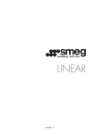
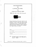
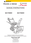
SERVICE AGENT TRAINING
2013
TRAINING SEMINAR
Contents
1. NEW PRODUCTS
2. INDUCTION
3. DISHWASHERS
4. OVENS
5. COOKERS
6. RANGE HOODS
7. GENERAL POINTS
8. ON-LINE WARRANTY AND WEBSITE
NEW PRODUCTS
2013
29/05/2015
3
NEW PRODUCTS
Dishwashers
DWA214 / 315 – Current model updates
DWIFAB – Retro style BLVO replacement
Ovens
SF, SFA & SFPA - Current model updates
DOA330 & SOA330 – New 70cm single & double wall ovens
Cooker
TRA4110 – 110cm four door gas/electric
NEW PRODUCTS
Ovens
BS, BSO, BSP & BOR – New model 60cm
Refrigeration
BRCIF7030 – New model bottom mount Fridge Freezer,
190lt/56lt
NEW PRODUCTS
Ovens
CLO, CLDO, CLOS – Updated 60cm single and double ovens
Waste disposers
CLWD12 – Replacement for model 400 waste disposer, ½
Horsepower DC motor with optional air switch
NEW PRODUCTS
Waste disposers
GAWD12 & GAWD34 – Replacements for the 400 (GAWD12)
and the 600 (GAWD34) waste disposers both supplied with
air switch. The GAWD12 is a ½ horsepower DC motor unit.
The GAWD34 is a ¾ horsepower AC induction motor unit.
INDUCTION
29/05/2015
8
INDUCTION
General Principles
What follows are excerpts from service manuals and
presentations supplied by Brandt and Smeg. Brandt is a
major supplier to various manufacturers who re-brand the
units for their market. Their technologies include IX1 to IX7
and the IX4000 series.
Other technology types are EGO Basic, EGO G3 and EGO
G4. Regardless of the technology used, the general
operation and underlying principles remain the same.
The Induction Hob working principle
INDUCTION
Multiple coil cooking zone
Some units will have one or more cooking zones with two or
three pot diameter outlines. These have a induction coil for
each diameter and the appropriate coil will be powered
according to the pot size used.
INDUCTION
Multi-zone
The Smeg SIM62B and
SIM91B have multi-zone
cooking zones. The zone is
rectangular in shape and is
comprised of six induction
coils in two groups of three.
Each group of three is in
series and is powered by its
own generator. They will
power share when on a high
output.
INDUCTION
BKF24IDB Dismantling
INDUCTION
Further Information
The service manual from Brandt which is used in this
presentation and the presentation from Smeg are available on
request from the Applico Technical Department
DISHWASHERS
29/05/2015
22
DISHWASHERS
DWA149 & DWAFI152 T– Setting the Test Cycle
DISHWASHERS
DWA-DWAU149/157 Test Cycle
DISHWASHERS
DWA-DWAU149/157 Error codes
DISHWASHERS
DWAFI149/152T Test Cycle
DISHWASHERS
DWAFI149/152T Error codes
DISHWASHERS
DWA Series Technical Data
DISHWASHERS
DWA Series Technical Data
This data is common to all the DWA model dishwashers
DISHWASHERS
DWA Series: Noisy or Poor Wash Issue
DISHWASHERS
DWA Series: Alternate Valve
There are two different suppliers for the alternate valve. They
are interchangeable, the only difference being the power
connections as shown below.
DISHWASHERS
DWA*315 Series
Water Reservoir
DISHWASHERS
DWA*315 Series
Water Reservoir
DISHWASHERS
DWA*315 Series
Water Reservoir
DISHWASHERS
DWA*315 Series
New 3rd basket for cutlery, FlexiDuo
DISHWASHERS
BKDW45, BKDW60 Control Boards
The control boards for these
two models appear to be
identical, however there are
two bridges on the board that
control the water volume, 3.7l
for the 60cm and 2.8l for the
45cm.
These bridges are at P7 and
P4 as shown in the following
slide.
DISHWASHERS
BKDW45, BKDW60 Control Boards
The board with both P4 and
P7 bridged is for the 45cm
model and is part
674001000246.
The board with only P4
bridged is for the 60cm model
and is part 674001000239.
Note that these are the same
boards used in the Classique
models
OVENS
29/05/2015
38
OVENS
SC45V/SCA45V2 Combination Steam Oven
OVENS
SC45V/SCA45V2 Combination Steam Oven
OVENS
SC45V/SCA45V2 Combination Steam Oven
OVENS
SC45V/SCA45V2 Combination Steam Oven
OVENS
SC45V/SCA45V2 Combination Steam Oven
OVENS
SC45V/SCA45V2 Combination Steam Oven
OVENS
SC45V/SCA45V2 Combination Steam Oven
The service manual for the Steam Ovens models SC45V and
SCA45V2 is available from the Technical department on
request.
OVENS
SC45V Combination Steam Oven
Regarding an air lock in the system,
sometimes it is possible for the nonreturn valve (included in the pump) to be
blocked, thus causing problems with the
hydraulic circuit. To unblock the pump
you can follow two different ways:
1st Solution:
• Disconnect the water inlet pipe (from
the water tank 5 and the pump 1)
• Blow compressed air in the pump
inlet connection or (even better) inject
water in the same connector using a
syringe
• Reconnect the water inlet pipe and
test again the machine
OVENS
SC45V Combination Steam Oven
2nd Solution:
The display colour of all the
new models is identical (blue)
however the intensity of the
SC45V display is higher than
the other half and full ovens.
The half ovens do not have
automatic dimming of the
display
OVENS
SC45MC Combination Microwave Oven
The thickness of
the door hooks
should be
checked when
attending a
service call to one
of these units. If
they are not
3.2mm (1/8”)
thick the kit
should be
ordered and the
components
replaced.
OVENS
SC45MC Combination Microwave Oven
These units have had a
power/display board
replacement to increase
reliability. The boards in
question are part numbers
811651502, 811651503,
811651504 or 811651505.
These boards should be
returned to Applico when
replaced as per the
instructions of PB2012-06SM-OVMW-00.
OVENS
SC45MC Combination Microwave Oven
OVENS
SC45MC Combination Microwave Oven
OVENS
SC45MC Combination Microwave Oven
Remember to check the correct operation of
the door switches (input and output) before
assuming a PCB fault.
OVENS
DOA330 & SOA330 Models
OVENS
DOA330 & SOA330 Models
OVENS
SF120, 130 & 140 Models
SF140
SF120
SF130
OVENS
SF120 USER INTERFACE
OVENS
SF120 USER INTERFACE
Secondary menu
• commands block
• show room
• low power mode
Timers
• minute minder
• cooking duration
• delayed end of
cooking
Cleaning
• pyrolysis
• eco pyrolysis
• vapor clean
Other characteristics
• Defrost and leavening function
• Lamp power manual control
• Automatic lamp switching off in low power mode after 20 seconds
OVENS
SF120 TEST MODE
There are two test modes available with the new model ovens, a manual mode –
used at the factory for end of line testing, and a self test mode for service
purposes. BOTH MODES ARE AVAILABLE TO THE SERVICE PERSON
End of line testing
• used on the assembly line
• manual procedure
• control with external
measuring device
• check of temperature sensor
and potentiometers
• display check
Self-test card
• used in service interventions
• automatic testing without
external measurement
• manual testing with operator
control
• check of temperature sensor
and potentiometers
• display check
OVENS
SF130 USER INTERFACE
Main menu
Timers
Functions menu
Pre-stored recipes
OVENS
SF140 USER INTERFACE
Main menu
Active functions
Pre-stored recipes
Functions menu
Timers
Custom recipes
OVENS
NEW POWER BOARD – 3RD GENERATION
•
•
•
•
Design of new models with new displays
Hardware compatibility with currently produced models
Increased possibility to control other types of display
Power supply modified for stand-by normatives (< 1W from
01.01.2013)
• Extra relay added for future developments
• Additional devices have been introduced in order to
manage further controls for future versions
• Added feedback on grill and sole resistances
OVENS
NEW POWER BOARD – 3RD GENERATION
New connector foreseen
for display connection
Introduction of serial connection
for external boards
OVENS
NEW POWER BOARD – 3RD GENERATION
Modified faston connector
(asymmetrical) to avoid
inversion in assembly
The circular heating element wiring has
been modified to increase safety
OVENS
NEW POWER BOARD – CLOSED CIRCUIT TESTS
Purpose: to allow mP to assess the presence and function of the
components connected to the relays
The following actuators are checked:
RL2:
RL3:
RL4:
RL6:
RL7:
RL8:
RL9:
RL10:
RL11:
Grill heating element RG
Fan heating element RV
Bottom heating element RS
cooling fan ECF @ MAX speed
cooling fan ECF @ MIN speed
door lock actuator BP
Auxiliary resistor 1 AUX1
Oven fan MTV
Auxiliary resistor 2 AUX2
OVENS
NEW POWER BOARD – ERROR CODES
Err1: faulty temperature sensor
Activated if the signal from the PT1000 sensor (converted in °C) provides
a temperature value out of the -20°C / 600°C range for at least 10sec
Danger: high internal temperatures that may endanger the user’s health
Actions
All the heating elements switched OFF - ECF (cooling motor) ON at MAX
speed
Cooking cycle STOPPED - Buzzer ON
The alarm condition disappears:
• If measured T is within the range for at least 10 consecutive seconds
• The display is switched to STAND-BY (e.g. handle in 0 position)
If the alarm is reset but the alarm condition remains, it is reactivated as
soon as the oven is reactivated
OVENS
NEW POWER BOARD – ERROR CODES
Err2: temperature too high
•
Measured temperature > 410°C for 10sec and the pyrolisis is not
active
Danger : high internal temperatures that may endanger the user’s health
Actions
Door-lock activated –
All the heating elements are switched OFF –
ECF ON at MAX speed
Cooking cycle STOPPED - Buzzer ON
The alarm condition disappears:
• If measured T is within the range for at least 10 consecutive seconds
• The display is switched to STAND-BY (e.g. handle in 0 position)
If the alarm is reset but the alarm condition remains, it is reactivated as soon as the
oven is reactivated
OVENS
NEW POWER BOARD – ERROR CODES
Err4: door-lock wrongly activated
•
•
Pyrolytic cycle selected and door-lock not activated within 90sec
Pyrolytic cycle not selected and door-lock activated (in this case the
door-lock has been activated by the external safety Tstat due to T
excessively high)
Danger : high internal temperatures that may endanger the user’s health
Actions
All the heating elements are switched OFF – ECF ON at MAX speed
Cooking cycle STOPPED - Buzzer ON
The alarm condition disappears:
• Cool oven at the end of the pyrolysis and door-lock not activated
• The display is switched to STAND-BY (e.g. handle in 0 position)
OVENS
NEW POWER BOARD – ERROR CODES
Err5: circular heating element error
• Relay active when SW does not expect it to be
• The fan heating element RV is disconnected or interrupted
• The safety Tstat has opened and the internal temperature < 150°C
Actions
All the heating elements are switched OFF – ECF ON at MAX speed
Cooking cycle STOPPED - Buzzer ON
The alarm condition disappears:
• The cause of the alarm has disappeared (e.g. RV reconnected)
• The display is switched to STAND-BY (e.g. handle in 0 position)
OVENS
NEW POWER BOARD – ERROR CODES
Err6: oven internal fan MTV error
• MTV not connected
• MTV relay not closed when SW expects it to be
Actions
All the heating elements are switched OFF – ECF ON at MAX
speed
Cooking cycle STOPPED - Buzzer ON
The alarm condition disappears:
• The cause of the alarm has disappeared (e.g. RV reconnected)
• The display is switched to STAND-BY (e.g. handle in 0 position)
OVENS
NEW POWER BOARD – ERROR CODES
Err7: grill heating element RG error
•
•
•
Relay active when SW does not expect it to be
The heating element is disconnected
The safety Tstat has opened and the internal temperature < 150°C
Danger : high internal temperatures that may endanger the user’s health
Actions
All the heating elements are switched OFF – ECF ON at MAX speed
Cooking cycle STOPPED - Buzzer ON
The alarm condition disappears:
•
The cause of the alarm has disappeared (e.g. RV reconnected)
•
The display is switched to STAND-BY (e.g. handle in 0 position)
OVENS
NEW POWER BOARD – ERROR CODES
Err8: ECF tangential cooling fan error
• ECF not connected
• ECF relay not closed when SW expects it to be
Risk: potential damage to electrical components on the control panel and high
temperatures on the front panel.
Actions
All the heating elements are switched OFF – ECF ON at MAX speed
Cooking cycle STOPPED - Buzzer ON
The alarm condition disappears:
•
The cause of the alarm has disappeared (e.g. RV reconnected)
•
The display is switched to STAND-BY (e.g. handle in 0 position)
OVENS
NEW POWER BOARD – ERROR CODES
Err9: bottom heating element RS error
•
•
•
Relay active when the SW does not expect it to be
The heating element is disconnected
The safety Tstat has opened and the internal temperature < 150°C
Danger : high internal temperatures that may endanger the user’s health
Actions
All the heating elements are switched OFF – ECF ON at MAX speed
Cooking cycle STOPPED - Buzzer ON
The alarm condition disappears:
•
The cause of the alarm has disappeared (e.g. RV reconnected)
•
The display is switched to STAND-BY (e.g. handle in 0 position)
OVENS
Pre-heating operation – old models
SAP112-8
Preheating phase
Cooking phase
Function on the display
Function/Element used
Function/Element used
ECO with CIRCULAR
FAN element + internal fan (IF)
FAN element + IF
STATIC
GRILL + BOTTOM element
GRILL + BOTTOM element
GRILL
GRILL + TOP element
GRILL + TOP element
Rotisserie GRILL
GRILL + TOP element + turnspit
GRILL element + turnspit
STATIC fan assisted
GRILL + BOTTOM element + IF
GRILL + BOTTOM element + IF
GRILL fan assisted
GRILL + TOP element + IF
GRILL + TOP element + IF
BOTTOM fan assisted
GRILL + BOTTOM element + IF
GRILL + BOTTOM element + IF
CIRCULAR
FAN element + IF
FAN element + IF
TURBO
FAN element + IF
GRILL + FAN + BOTTOM elem. + IF
DEFROSTING and PROVING
GRILL + IF
GRILL + IF
PYRO ECO
GRILL + BOTTOM element
GRILL + BOTTOM element
PYRO
GRILL + BOTTOM element
GRILL + BOTTOM element
OVENS
Pre-heating operation – old models
SCP160/171
FUNCTION
HEATING ELEMENT 1
HEATING ELEMENT 2
HEATING ELEMENT 3
OTHER
ECO STATIC
GRILL 1800W
STATIC
UPPER 100W
LOWER
LOWER 1300W
LOWER 1300W
-
-
GRILL 1800W
LOWER 1300W
LOWER 1300W
-
-
SERIES 2400W
LOWER 1300W
-
-
-
-
WIDE GRILL
GRILL 1800W
-
-
-
-
NARROW GRILL
GRILL 1800W
-
-
-
-
-
VENTILATED
NARROW GRILL
GRILL 1800W
-
-
FAN MOTOR
-
-
VENTILATED WIDE
GRILL
GRILL 1800W
UPPER 100W
-
FAN MOTOR
SERIES 2400W + FAN
GRILL 1800W + FAN
STATIC VENTILATED
UPPER 100W
LOWER 1300W
-
FAN MOTOR
SERIES 2400W + FAN
LOWER 1300W + FAN
LOWER VENTILATED
LOWER 1300W
-
-
FAN MOTOR
-
-
CIRCULAR
CIRC 2700W
-
-
FAN MOTOR
-
-
TURBO
CIRC 2700W
UPPER 100W
UPPER 100W
LOWER 1300W
FAN MOTOR
PHASE 1
CIRC 2700W + FAN
PHASE 2
UPPER + LOWER +
2400W + FAN
OVENS
Pre-heating operation – new models
SFPA395X - SFPA130
Preheating phase
Cooking phase
Function on the display
Function/Element used
Function/Element used
ECO with CIRCULAR
FAN element + internal fan (IF)
FAN element + IF
50
280
STATIC
GRILL + BOTTOM element
GRILL + BOTTOM element
50
280
GRILL
GRILL + TOP element
GRILL + TOP element
50
280
BOTTOM
GRILL + BOTTOM element
GRILL + BOTTOM element
50
280
STATIC fan assisted
GRILL + BOTTOM element + IF
GRILL + BOTTOM element + IF
50
280
GRILL fan assisted
GRILL + TOP element + IF
GRILL + TOP element + IF
50
280
BOTTOM fan assisted
GRILL + BOTTOM element + IF
GRILL + BOTTOM element + IF
50
280
CIRCULAR
FAN element + IF
FAN element + IF
50
280
TURBO
FAN element + IF
GRILL + FAN + BOTTOM elem. + IF
50
280
CIRCULAR+GRILL fan assisted
FAN + GRILL elem. + IF
FAN + GRILL elem. + IF
50
280
PROVING
GRILL element
GRILL element
40
40
DEFROSTING
GRILL element + IF
GRILL element + IF
30
30
FOOD WARMING
FAN element + IF
FAN element + IF
40
80
KEEP WARM
GRILL + BOTTOM element
GRILL + BOTTOM element
60
100
PYRO ECO
GRILL + BOTTOM element
GRILL + BOTTOM element
470
470
PYRO
GRILL + BOTTOM element
GRILL + BOTTOM element
470
470
°min
°max
OVENS
SA708 Commutator
A modification has been made
by Smeg on some of the new
70cm model ovens. This is to
relieve the loading of the
commutator (811730261). It
entails fitting two relay boards
(811650197) to switch the load
of the broil/grill element.
We are trying to ascertain if
this can be done retroactively
to older models.
COOKERS
29/05/2015
77
COOKERS
TRA4110
This is a traditional styled
four door cooker with a gas
hob. It has two 60cm ovens
with fan assist (lower left and
upper right), a dedicated
griller (upper left) and a
storage/warming drawer.
The hob has seven burners,
two auxiliary, two semi rapid,
two rapid and one ultra-rapid
triple crown and is supplied
with a teppanyaki plate.
COOKERS
TRA4110
• Each oven is protected by individual safety thermostat
• Programmed cooking is only possible in the multi function
oven (upper right)
• There are two cooling fans, one is operated when the
standard oven (lower left) or grill oven (upper left)is used,
the other operates when the multifunction oven (upper
right) is used
• The grill oven has only a broil/grill element
• The standard oven has broil/grill and lower elements with
fan
• The multifunction oven has broil/grill, circular and lower
elements with fan
COOKERS
TRA4110
COOKERS
TRA4110
Below are the commutator diagrams for each oven indicating
the function and contact state for each position.
RANGE HOODS
29/05/2015
82
RANGE HOODS
Low voltage transformer
A number of canopy and power pack range hoods we source
from Europe have a 12 volt supply for the lights and the
control board. If the transformer fails the unit will cease to
operate and a faulty control board may be diagnosed. The
transformer output must be checked before replacing the
control board.
RANGE HOODS
Low voltage transformer
Both of the diagrams below have a 12V supply to the PCB
from an external transformer.
The diagram on the left is for the CK2000 Power Pack and
the one on the right is for the KASC7088LCD90 Canopy hood
GENERAL PRACTICES
Connectors
29/05/2015
85
General practices
Crimp Connectors
The break down of a conductor connection can be
summarised into three categories.
• Disconnection of the connector to the receptacle
• Disconnection between the conductor and the connection
• Burning of connector-conductor-terminal due to electric
overheating (Joule effect).
While the first two categories are fairly self explanatory, the
third category has more complex origins. We will take a short
look at the performance of a connection system
(wiring/connectors) during passage of an electric current.
General practices
Crimp Connectors
As we know when a current is passed through a resistance
there is a heating of the resistance, referred to as Joule
effect. The amount of energy W (expressed in Joule)
dissipated as heat, in the time t (expressed in seconds)
depends on the square of the current I and is defined by the
relationship:
P = R × I2
Where I is the current expressed in amperes (A), R is the
resistance expressed in Ohms (Ω) and P is the dissipated
power expressed in Watts (W).
General practices
Crimp Connectors
The passage of current through a conductor always creates
an energy transformation, with the following four effects:
• Thermal, Chemical, Physiological (physical) and Magnetic
These effects are manifested in different ways according to
whether the current is continuous or alternate. The thermal
effect is known as Joule effect and is manifested with a
heating which may reach incandescence of a conductor.
General practices
Crimp Connectors
The results of poor
connector termination
General practices
Crimp Connectors
REMEMBER TO…
Cut the conductor back until you have undamaged wire.
Use the correct connections for the conductor(s) and
terminal.
Utilise the correct tools for the job.
Check the connection before fitting to the terminal, and
again after fitting.
INTERNET
Website Use and On Line Warranty
29/05/2015
91
INTERNET
ONLINE WARRANTY
Applico has invested in an online warranty system to speed up processing and payment of
warranty claims.
It will up to the Service Agent to enter the claim details online and submit the claim for
payment
This system will be rolled out gradually during the year
This will also enable the new Applico service site
Process
Customer registers their product Online
Customer requests a service Online
Applico assigns a Service Agent to the job
Service Agent accepts job
Service Agent enters details of Job online
and submits for payment
Applico process claim and payment authorised
THANK YOU FOR YOUR
ATTENDANCE
Presented by:
Richard Saberon
&
Wayne Edmonds