1
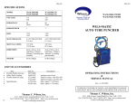
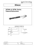
SM-253
SM-253
SPECIFICATIONS
909-1900
909-2000
909-2100
Model no.
Type
Free Speed (RPM)
Min. Torque Ft-Lb
Max. Torque Ft-Lb
Air Pressure psi
Air Inlet
Hose
Air Flow @Free
Speed
Spindle
Weight
909-1900
909-2000
909-2100
Roll Throttle
Stall Type
Lever Throttle
Torque Control
Roll Throttle
Torque Control
90
90
90
150
150
150
305
305
305
90
90
90
1/2” NPT
1/2” NPT
1/2” NPT
1/2” I.D.
1/2” I.D.
1/2” I.D.
90 CFM
90 CFM
90 CFM
3/4” square
3/4” square
3/4” square
18.5 Lb (8.8kg)
18.5 Lb (8.8kg)
18.5 Lb (8.8kg)
SERIES 909
RIGH ANGLE TUBE ROLLER
OPERATING INSTRUCTIONS
&
SERVICE MANUAL
Rev: A, 2/23/2007
TO REDUCE THE RISK OF INJURY AND EQUIPMENT DAMAGE
USER MUST READ AND UNDERSTAND OPERATOR’S MANUAL.
20
Thomas C. Wilson, Inc.
Thomas C. Wilson, Inc.
21-11 44th Avenue, Long Island City, New York 11101
Tel: (718)729-3360 Fax: (718)361-2872 http://www.tcwilson.com
E-mail: tcwilson@tcwilson.com
21-11 44th Avenue, Long Island City, New York 11101
Tel: (718)729-3360 Fax: (718)361-2872 http://www.tcwilson.com
E-mail: tcwilson@tcwilson.com
SM-253
SAFETY INSTRUCTIONS
SM-253
TROUBLE-SHOOTING
PROBLEM
!
WARNING!
Motor will not run.
CAUSE & REMEDY
1.
READ AND UNDERSTAND ALL INSTRUCTIONS
Failure to follow all instructions listed below, may result
in accident, fire and/or personal injury.
Insufficient air supply
—Check 90 psi and 90 CFM air supply.
2.
Clogged air inlet screen
—Replace or Clean
SAVE THESE INSTRUCTIONS
3.
Broken or severely worn rotor blades
—Replace.
1.
Do not allow corrosive gases or foreign material to enter the unit. Moisture, oilbased contaminants, or other liquids must be filtered out.
4.
Rust due to improper storage of tool
—Disassemble and clean– Refer to Disassembly
procedure.
2.
Eye protection is always required when running motor.
5.
Broken throttle valve pin or lever
3.
Hearing protection is recommended when in close proximity to all operating air
motors.
1.
Insufficient air volume
—Check 90 CFM supply.
Dirty air inlet screen
—Clean.
Worn rotor blades
—Replace.
Air supply hose chocked or too small
—See Operating Procedure recommended hose.
Rotor Assembled incorrectly
—Re-assemble referring to assembly
procedure.
4.
Motor will not reach
RPM.
2.
Dust mask, non-skid safety shoes, hard hat, gloves and other personal safety equipment must be used.
3.
5.
Stay alert, watch what you are doing, and use common sense when operating a
power tool.
4.
6.
Dress properly. Do not wear loose clothing or jewelry.
5.
7.
Keep your work area clean and well lit.
8.
Do not operate power tools in explosive atmospheres, such as in the presence of
flammable liquids, gases, or dust.
9.
Motor stalls at high torque 1.
2.
Disconnect the tool from the air supply before installing, making any adjustment,
changing accessories, servicing or storing tool.
3.
Motor fails to stop
1.
2.
2
Insufficient air pressure
—Check 90 psi supply
Dirty air inlet screen
—Clean.
Rotor blades worn, chipped or broken
—Replace.
Broken throttle valve spring
—Replace.
Valve ball does not seal
—Replace or rework valve seat.
19
SM-253
DISASSEMBLY
Right Angle Head
When installing needle bearings, press only on the bearing's stamped end. The
pinion needle bearing should be slipped on the pinion gear and pressed into the
housing to the following depth:
#230 Right Angle Head = 3-3/16" (81 mm)
#110 Right Angle Head = 3" (76.2 mm)
The pinion bearing retainer, No. 909-2116, should be securely tightened to
ensure proper gear make-up.
The driven gear bearing cap should be torqued to 100/ 110 ft.-lb, (1 35/1
49Nm) and the bearing cap lock screw torqued to 10 in -lb (1 1.52cmkg) minimum.
NOTE: When assembling the angle head to the complete tool, the clamp nut,
No. 909-2117, (left hand threads) must be torqued to 100/110 ft.-lbs. (135/
149Nm).
Trip Rod Sizing
During reassembly of the tools, the trip rod must be ground flush (+0/-1/32)
(+0/-0.793mm) with the end of the rotor. Hold the motor firmly in the handle
at the time the trip rod is being sized to length.
Safety Check
After repair or replacement of parts, tools equipped with an automatic shutoff
device should be tested to verify that they are functioning properly.
CAUTION: To prevent hand entrapment from torque reaction, the square drive
should be positioned from the throttle as shown below.
SM-253
OPERATION
Always operate, inspect and maintain this tool in accordance with American National
Standards Institute Safety Code for Portable Air Tools (ANSI B186.1) and any other
applicable safety codes and regulations.
FOR TOP PERFORMANCE AND MAXIMUM DURABILITY OF PARTS, OPERATE THIS TOOL AT 90 psig (6.2bar/620kPa) AIR PRESSURE WITH ½” (13mm)
DIAMETER HOSE.
WARNING: Always turn off the air supply and disconnect the air supply hose before
installing, removing or adjusting any accessory on this tool, or before performing any
maintenance on this tool. Failure to do could result in injury.
Air powered tools can vibrate in use. Repetitive motions, uncomfortable positions,
vibrations can cause injury to hands, fingers, wrists of some persons. Stop using any
tool if discomfort, tingling felling or pain occurs. Seek medical advice before resuming use.
HOSE AND HOSE CONNECTIONS
Use ½” (13mm) hose or hose fitting with a Male Hose Nipple (1/2” hose to ½” male
pipe) for attaching it to the tube Roller. A smaller hose or hose fitting will reduce the
power and efficiency of the Tube Roller.
LUBRICATION
After each two or three hours of operation, unless an Air Line Lubricator is used, disconnect the air hose and pour into the inlet about 3cc of SAE No. 10 or ‘Wilsolub’
Pneumatic motor oil Cat. No. 9047. The use of an Air Line Lubricator is recommended with any air-operated tool. Install a Wilson automatic lubricator Cat. No. 8597
as close to the tool as possible. Gearing and Right-Angle Assembly should be grease
lubricated approximately every 160 hours of operation. Inject bearing type grease, 1 to
2 strokes through grease fitting in housing.
HIGH TORQUE TOOL - ALWAYS USE PROPER REACTION BAR
IMPORTANT: The reaction bracket, No. 909-2103, must fully engage the spline on the right
angle head. Position the bracket forward on the small diameter of the head and then
move it rearward to engage the spline. Securely tighten reaction bar (with pipe
wrench), screws and jam nuts.
USE ONLY SOCKETS APPROVED FOR POWER TOOL SERVICE.
ALWAYS WEAR APPROVED EYE PROTECTION. (See the latest edition of ANSI Z87.1 American National Standard for Occupational and Educational Eye and Face Protection.
READ, UNDERSTAND, AND PRACTICE the requirements of ANSI B186.1, Safety Code for
portable air tools.
18
3
SM-253
OPERATION (Cont’)
909-2000 & -2100 TUBE ROLLER
The Model 909-2100 Tube Roller is designed to operate on 90 PSIG air pressure, but
does not depend on controlled air pressure to maintain accurate torque. Accurate
torque is achieved by setting the clutch to the desired torque on the application. The
tool will shut off automatically at this torque. Releasing the throttle will allow the tool
to reset for the next cycle.
Clutch Adjustment
Rotate the adjustment cover until the adjustment slot is uncovered. With the angle
head end of the tool facing away, use the 909-2127 adjusting tool or a 5/32" diameter
pin to rotate the adjusting nut clockwise to increase the torque setting and counterclockwise to
decrease the setting. After adjustment, rotate the
cover over the slot to lock the nut in place.
CAUTION: If the clutch is adjusted over the
maximum power output of the tool, the clutch
will not function and the tool will operate like a
stall-type tool. Also, if the tool is being operated
at its upper torque limits, a drop in air pressure
could cause the clutch not to function due to a
loss of motor power and the tool will function like a stall type tool.
Operational Check: Grip tool securely and be prepared to counteract stall torque in
case clutch is improperly adjusted. Use proper reaction bar.
Torque Setting
By looking into the clutch adjustment access
hole, markings can be seen on the adjusting nut.
NOTE: The marking centered in the access
slot is the one to read.
Five revolutions of the adjusting nut covers the
complete torque range of the tool. The markings start at A-1(lowest torque setting) and go thru A-8 on the first revolution of the
nut. The second revolution starts with B-1, the third starts with C-1, etc. The fifth
revolution ends with E-8 (highest torque setting).
NOTE: The torque setting marks are for reference only and do not relate to a specific
amount of torque.
4
SM-253
DISASSEMBLY
Handle
Unscrew the inlet bushing, No. 909-2194, for inspection of the throttle components. The air inlet screen, No. 909-2175, should be washed in a solvent and
blown out in the reverse of normal airflow. Replace if damaged or clogged.
Reassembly
The tool is reassembled in the reverse order of disassembly. Clean all parts thoroughly in a solvent and inspect for damage or wear. Check all bearings for wear
which can be detected by excessive endplay and/or roughness that would indicate
a brinelled condition. The rotor blades should be replaced if they measure less
than 3/8" (9.5mm) at either end. All gear teeth, bearings, and pins should receive
a close inspection and be replaced if necessary. All gears and open bearings
should receive a generous amount of No 2 Moly grease during reassembly.
Motor Reassembly
To assemble the motor, install the rear rotor bearing into the rear bearing plate.
Make sure the outer bearing race is firmly seated in the bearing plate. Clamp the
rotor body lightly in the vise with the threaded end up and slip the rear bearing
plate assembly onto the rotor shaft far enough for the bearing lock nut to start.
Tighten the lock nut until there is approximately .001 "/ .001 5" (0.025/0.038mm)
clearance between the rotor and bearing plate. The outer bearing race should be
firmly seated and the rotor bumped forward when checking this clearance. Pack
both rotor bearings with a good grade of No. 2 Moly grease after assembly of the
motor unit.
IMPORTANT:During reassembly of the complete tool, it is important that the
motor be free. After the tool is completely assembled, the right angle square drive
spindle should turn freely using a small hand wrench. If the spindle does not turn
freely, the motor should be checked for proper spacing Do not run the tool until
the spindle turns freely. Failure to do this could result in damage to motor components.
1st REDUCTION GEAR TRAIN REASSEMBLY
- 2 Gear Train (13 Tooth Spider)
21 Tooth idler gears on inner set of gear pins.
-3 Gear Train (19 Tooth Spider)
21 Tooth idler gears on inner set of gear pins.
Clutch Reassembly
The clutch is reassembled in the reverse order of disassembly. The torque spring
bearing, No. 909-2160, must be assembled so that the solid side of the ball separator is facing the torque spring plate, No. 909-2156.
17
SM-253
SM-253
DISASSEMBLY
DISASSEMBLY - General
Clamp the flats of the handle in a vise with the tool in a vertical position.
Using a suitable wrench, loosen (left hand threads) the clamp nut, No. 909-2117,
and remove the angle head assembly. Unscrew and remove the clutch housing
and gear case assemblies. Clamp the gear case in the vise and unscrew the clutch
housing. Slip the motor unit out the front of the handle. It may be necessary to
bump the handle on the work bench to loosen the motor.
Right Angle Head
Remove the bearing cap lock screw (1/16 hex), No. 909-2112, and unscrew (left
hand threads) the bearing cap. Clamp the square drive in the vise and use a soft
mallet to drive the angle head off. Press the spindle out of the driven gear and
then press the spindle out of the ball bearing.
Unscrew and remove the bearing retainer, No. 909-2116, and grease plug, No.
909-2111. Use a suitable driver to drive the pinion gear out of the housing.
Clutch
CAUTION: The adjustment cover, No. 909-2168, retains the ball spring, No. 9092169, and steel ball, No. 24031-0000, and care should be exercised to prevent
their loss.
Use a 5/32" (3.96mm) diameter pin to lower the clutch adjustment. This will allow the clutch retainer ring, No. 909-2170, to be removed from the clutch housing.
Remove the clutch assembly from the housing. Use a suitable bearing puller to
remove ball bearing, No. 909-2154. Remove retainer ring, No. 909-2153, drive
shaft washer, No. 909-2155, trip sleeve spring, No. 909-2159, and trip sleeve, No.
909-2157, from the drive shaft, No. 909-2165. NOTE: Trip Plunger, No. 9092166, trip plunger spring, No. 909-2158, and two (2) balls, No. 909-2151, should
also be removed at this time. Use a sharp pointed instrument to remove the cam
retainer ring, No. 909-2171, from the ball retainer, No. 909-2164. Slip the drive
shaft, No. 909-2165, and clutch cam, No. 909-2163, out the rear of the ball retainer, No. 909-2164.
16
OPERATION (Cont’)
909-1900 TUBE ROLLER
The 1900 Stall Type Model Tube Roller is designed to develop max torque at 90
PSIG air pressure and it doesn't have clutch adjustment. Torque output can be controlled by a pressure regulator installed in the air supply line.
MAINTENANCE
WARNING
Always turn off the air supply and disconnect the air supply hose before installing, removing or adjusting any accessory on this tool, or before performing any maintenance on this tool. Failure to do could result in injury.
Air tools are made of precision parts and should be handled with reasonable care
when servicing.
Excessive pressure exerted by a holding device may cause distortion of a part. Apply pressure evenly when disassembling ( or assembling ) parts which have a press
fit.
When removing or installing bearing, apply pressure to the bearing race that will be
the press fit to mating part; if this is not practiced, Brinelling of the bearing race
may occur making replacement necessary.
It is important that the correct tools and fixtures are used when servicing this tool.
Disassembly should be done on a clean work bench with a clean cloth spread to
prevent the loss of small parts. After disassembly is completed; all parts should be
thoroughly washed in a clean solvent, blown dry with air and inspected for wear
levels, abuse and contamination.
Gear Case
Slip the entire gear train out the rear of the gear case. The 2nd reduction idler
gears may be removed for inspection by driving the idler gear pins, No. 66370000, out the rear of the spider.
Double sealed or shielded bearings should never be placed in solvent unless a good
method of re-lubricating the bearing is available. Open bearings may be washed
but should not be allowed to spin while being blown dry. When replacement parts
are necessary, consult drawing containing the parts for identification.
Motor
Use a soft-faced mallet to drive the rotor out of the front rotor bearing, No. 9092154. This will allow the removal of the front bearing plate, No. 909-2185, cylinder, and five (5) rotor blades, No. 909-2188, from the rotor, No. 909-2186. Clamp
the rotor lightly in the vise and unscrew the rotor lock nut, No. 909-2181. Rest the
rear bearing plate on the vise jaws and use a soft faced mallet to drive the rotor out
of the rear rotor bearing.
Before reassembling, lubricate parts where required. Use bearing grade grease in
bearings. When assembling ‘O’ ring, care must be exercised to prevent damage to
the rubber sealing surfaces. A small amount of grease will usually hold steel balls
and small parts in place while assembling.
When ordering parts, be sure to list PART NUMBER, PART NAME, MODEL
NUMBER AND SERIAL NUMBER OF TOOL. USE ONLY GENIUE REPLACEMENT PARTS.
5
SM-253
SM-253
909-1900
909-2000
909-2100
6
ITEM
PART NO.
QTY
74
25170-0000
1
CYCLINDER PIN
DESCRIPTION
77
909-2154
1
ROTOR BEARING
81
909-2181
1
ROTOR LOCK NUT
83
6896-0000
1
MOTOR ALIGNMNET PIN
86
909-2236
1
ROTOR ASSEMBLY
87
909-2187
1
CYLINDER INCL. PIN
88
909-2188X
5
ROTOR BLADE
90
909-2190
1
REAR BEARING PLATE
107
909-2207
1
DEFLECTOR SPACER
108
909-2196
1
EXHAUST DEFLECTOR
109
909-2193
1
THROTTLE VALVE
110
909-2172
4
‘O’ RING
111
909-2173
1
‘O’ RING
112
909-2212
1
DOWEL PIN
113
909-2175
1
SCREEN
114
21941-0000
1
BALL
115
909-2215
1
REVERSE RING
116
909-21880
1
SPRING
117
909-2182
1
REVERSE VALVE SCREW
*Loctite In Place
118
909-2184
1
‘O’ RING
119
909-2192
1
THROTTLE VALVE SEAT
120
909-2194
1
INLET BUSHING
121
909-2198
1
SHUT-OFF VALVE
122
909-2199
1
TRIP ROD
123
909-2200
1
MOTOR SPACER
124
909-2201
1
REVERSING VALVE
125
909-2204
1
MUFFLER
126
909-2205
1
‘O’ RING
127
909-2227
1
HANDLE
128
909-2228
1
THROTTLE RETAINER
129
909-2229
1
VALVE ROD
130
909-2230
1
THROTTLE SLEEVE
131
909-2231
1
THROTTLE RETURN SPRING
15
SM-253
SM-253
PARTS LIST, 909-2270
NOTE:
On 909-1900 Model the trip rod, No. 909-2199 and
shut off valve, No. 909-2198 is removed from the
throttle assembly and the set screw, No. 20006-0000
is assembled in place on the rotor, No. 909-2186
14
7
SM-253
SM-253
PARTS LIST, 909-2280
8
ITEM
PART NO.
QTY
DESCRIPTION
51
34272-0000
11
STEEL BALL
52
24031-0000
1
STEEL BALL
53
909-2153
1
RETAINING RING
54
909-2154
1
BALL BEARING
55
909-2155
1
DRIVE SHAFT WASHER
56
909-2156
1
TORQUE SPRING PLATE
57
909-2157
1
TRIP SLEEVE
58
909-2158
1
TRIP PLUNGER SPRING
59
909-2159
1
TRIP SLEEVE SPRING
60
909-2160
1
TORQUE SPRING BEARING
61
909-2161
1
TORQUE SPRING
62
909-2162
1
CLUTCH HOUSING
63
909-2163
1
CLUTCH CAM
64
909-2164
1
BALL RETAINER
65
909-2165
1
DRIVE SHAFT
66
909-2166
1
TRIP PLUNGER
67
909-2167
1
ADJUSTING NUT
68
909-2168
1
ADJUSTMENT COVER
69
909-2169
1
BALL SPRING
70
909-2170
1
CLUTCH RETAINING RING
71
909-2171
1
CAM RETAINING RING
13
SM-253
SM-253
PARTS LIST, 909-2260
12
ITEM
PART NO.
QTY
DESCRIPTION
72
909-2172
4
‘O’ RING
73
909-2173
1
‘O’ RING
74
25170-0000
1
CYCLINDER PIN
75
909-2175
1
AIR INLET SCREEN
77
909-2154
1
ROTOR BEARING
80
909-2180
1
THROTTLE VALVE SPRING
81
909-2181
1
ROTOR LOCK NUT
82
909-2182
1
REVERSING VALVE SCREW
83
6896-0000
1
MOTOR ALIGNMNET PIN
84
909-2184
1
‘O’ RING
86
909-2236
1
ROTOR ASSEMBLY
87
909-2187
1
CYLINDER INCL. PIN
88
909-2188X
5
ROTOR BLADE
89
28136-0000
1
LEVER PIN
90
909-2190
1
REAR BEARING PLATE
92
909-2192
1
THROTTLE VALVE SEAT
93
909-2193
1
THROTTLE VALVE
94
909-2194
1
INLET BUSHING
95
909-2195
1
THROTTLE LEVER
96
909-2196
1
EXHAUST DEFLECTOR
98
909-2198
1
SHUT-OFF VALVE
99
909-2199
1
TRIP ROD
100
909-2200
1
MOTOR SPACER
101
909-2201
1
REVERSING VALVE
102
909-2202
1
HANDLE
103
909-2203
1
REVERSING RING
104
909-2204
1
MUFFLER
105
909-2205
1
‘O’ RING
106
909-2206
1
VALVE PIN
107
909-2235
1
SPACER
N.S.
909-2207
1
DEFLECTOR SPACER
9
SM-253
PARTS LIST, 909-2240
PARTS LIST, 909-2250
ITEM PART NO. QTY
10
SM-253
DESCRIPTION
1
909-2101
1
SPINDLE
6
909-2106
1
SPINDLE BEARING
8
909-2108
1
PINION BEARING
10
909-2110
1
GEAR SET CONSISTS OF:
ITEM PART NO. QTY
DESCRIPTION
909-2233
PINION GEAR
39
6633-0000
3
DOWEL PIN
909-2234
BEVEL GEAR
40
909-2140
3
IDLER BEARING
11
909-2111
1
GREASE PLUG
41
909-2141
1
SPIDER
12
909-2112
909-2113
1
BEARING SCREW
43
909-2143
3
IDLER GEAR
14
909-2114
1
RIGHT ANGLE HEAD
44
909-2144
3
IDLER GEAR
16
909-2116
1
BEARING RETAINER
46
909-2146
1
SPIDER
17
909-2117
1
CLAMP NUT
48
909-2148
1
GEAR CASE
18
909-2118
1
CLAMP RING
49
909-2149
39
NEEDLE ROLLER
19
909-2119
1
PINION BEARING
50
6637-0000
3
DOWEL PIN
22
909-2122
1
BEARING CAP
23
909-2123
1
SPINDLE BEARING
11