1
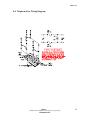
SSP-373-F-CAC6.00-650-521-ISSUE4.0
SERVICE MANUAL
FOR
MODEL SSP-373-F
STAINLESS STEEL ELEVATOR/
AUTOMATIC DIALING TELEPHONE
EQUIPPED WITH CAC6.00 FIMWARE
Serving the Telephone Industry Since 1930
Communication Equipment
& Engineering Company
519 West South Park Street
Okeechobee, FL 34972
Voice: 863-357-0798
Fax: 863-357-0006
ISSUE 4.0
IMPORTANT INFORMATION
FOR
CUSTOMER
Please fill in before you continue.
The following information is necessary when calling CEECO for assistance.
MODEL SSP-373-F EQUIPPED WITH CAC6.00
FIRMWARE.
MODEL NUMBER
SERIAL NUMBER
DATE MANUFACTURED
LOCATION INSTALLED
For us to better serve you, please have this information available when calling for
technical support.
CEECO
Communication Equipment and Engineering
Company
519 W South Park Street
Okeechobee, FL 34972
863-357-0798- telephone
863-357-0006- facsimile
info@ceeco.net
www.ceeco.net
CEECO
Communication Equipment & Engineering Company
PROPRIETARY
2
ISSUE 4.0
TABLE OF CONTENTS
SECTION
PAGE
1.0
INTRODUCTION.......................................................................................................................... 4
2.0
GENERAL DESCRIPTION ......................................................................................................... 4
3.0
PROGRAMMING ......................................................................................................................... 5
PROGRAMMING CONTINUED…............................................................................................. 6
PROGRAMMING CONTINUED…............................................................................................. 7
PROGRAMMING CONTINUED…............................................................................................. 8
4.0
TESTING/OPERATION............................................................................................................... 9
TESTING/OPERATION CONTINUED… ................................................................................ 10
5.0
OPERATION ............................................................................................................................... 11
6.0
RECOMMENDED TOOLS AND TEST EQUIPMENT.......................................................... 11
7.0
INSTALLATION NOTES AND ASSEMBLY INSTRUCTIONS ........................................... 12
8.0
TELEPHONE LINE WIRING DIAGRAM .............................................................................. 14
9.0
SPECIFICATIONS...................................................................................................................... 14
10.0
PARTS LIST ................................................................................................................................ 15
11.0
FCC NOTICE............................................................................................................................... 16
12.0
REPAIR AND RETURN INFORMATION .............................................................................. 17
13.0
WARRANTY POLICY ............................................................................................................... 18
14.0
DIAGRAM.................................................................................................................................... 19
CEECO
Communication Equipment & Engineering Company
PROPRIETARY
3
ISSUE 4.0
1.0
INTRODUCTION
The practices in this manual provide installation and maintenance information for
the Model SSP-373-F Stainless Steel Telephone, equipped with CAC6.00
software.
The information in this manual is subject to change without notification.
For information not included in this manual, please call or write:
CEECO
Customer Service
519 W South Park Street
Okeechobee, FL 34972
863-357-0798- telephone
863-357-0006- facsimile
info@ceeco.net
www.ceeco.net
2.0
GENERAL DESCRIPTION
The CEECO SSP-373-F Stainless Steel Panel Telephone is designed for elevator
and other applications, for typical dialing, call restricting, speed dialing, autodialing, fraud prevention, timed call duration and more. The telephone is
designed to be mounted in an optional CEECO mounting box (P/N 371-011) and
mounting box frame (P/N 371-012) The telephone is designed for vandal –
resistance as well. Custom software programs are available upon special request.
CEECO
Communication Equipment & Engineering Company
PROPRIETARY
4
ISSUE 4.0
3.0
PROGRAMMING
3.1
First read through the programming section and then do the actual
programming as you read along again. Programming is accomplished by
way of the DTMF keypad. The programming can be accomplished in one
continuous sequence without having to stop or perform any measures
between programming sections. It is important to be slow and deliberate
when pressing the keys during programming. A missed or partial tone
will result in improper programming. Connect the telephone to a working
telephone line or a DTMF test set.
3.2
Locate the two plastic mini-jumpers on the edge of the printed circuit
board and move them to the “ON” position, as depicted on the last page of
this manual.
3.3
Lift the handset and wait for dial tone before beginning programming.
3.4
Utilizing the keypad, enter # 9 7. This will clear all memory locations.
3.5
Enter # 0 0, which accesses the telephone options memory location.
There are six (6) selections to be made in this location. By entering a
selection into each of the six programming digit locations, the phone is
customized for the particular installation. You must make an entry for
each of the six digit locations. The six digit locations and the available
selections are shown on the next page. Compare the example below to the
information on the next page and then enter the 6 numbers you choose.
Example: Entering #00 followed by 101003 would program the phone to
have no call restrictions, no incoming call allowed, a wide dial tone detect
window, a muted microphone initially, DTMF dialing, and a 3 minute
automatic timed call disconnect.
CEECO
Communication Equipment & Engineering Company
PROPRIETARY
5
ISSUE 4.0
PROGRAMMING CONTINUED…
Location #00:
Digit 1
0
1
Implement Call restrictions
No call restrictions
Digit 2
0
1
No incoming calls allowed
Incoming calls allowed
Digit 3
0
1
Narrow dial tone detect window
Wide dial tone detect window (Always recommended)
Digit 4
0
1
Mute the microphone until the user dials a digit
Unmute the microphone after the access number is dialed
Digit 5
0
1
2
DTMF dialing
10 PPS pulse dialing
20 PPS pulse dialing
Digit 6
0=no call timeout
1=2 min.call timeout
2=3 min.call timeout
3=5 min.call timeout
4=10 min. call timeout
•
5=12 min.call timeout
6=15 min.call timeout
7=20 min.call timeout
8=25 min.call timeout
9=30 min.call timeout
Be sure to record your selections in the table below for future
reference.
Telephone Options Table: #00 __ __ __ __ __ __
1 2 3 4 5 6
CEECO
Communication Equipment & Engineering Company
PROPRIETARY
6
ISSUE 4.0
PROGRAMMING CONTINUED…
3.6
If you desire the phone to automatically dial a number (up to eleven
digits in length) when the handset is lifted, now is the time to enter it. If
this is not a desired function, proceed to section 3.9. Programming
location #19 stores the auto-dial number. Therefore, enter # 1 9 followed
by the desired auto dial number. For example: Entering #199 will
program the phone to automatically dial a 9, when the handset is lifted.
Be sure to record your entry in the table below for future reference.
1st Auto Dial Number Table: #19 __ __ __ __ __ __ __ __ __ __ __
3.7
If you desire the phone to automatically dial a second number (up to
eleven digits in length) after the one stored in location #19 (see above),
now is the time to enter it. If this is not a desired function, then proceed to
section 3.9. Programming location #18 stores the second auto dial
number. In order to use #18, you must first use #19. This number will
dial out approximately one second after any number stored in the #19
location. Enter # 1 8 followed by the desired auto dial number. For
example: Entering #1818005551212 will program the phone to dial 1800-555-1212 approximately one second after it dials the number stored in
location #19. Combining the examples from this section and the one
above, entering #199#1818005551212 will program the phone to
automatically dial 9, pause one second and automatically dial 1-800-5551212, when the handset is lifted. Be sure to record your entry in the table
below for future reference.
2nd Auto Dial Number Table: #18 __ __ __ __ __ __ __ __ __ __ __
3.8
If you have a normal 3 x 4 keypad and you desire to have speed-dialing
capability, now is the time to program it. If this is not a desired function,
proceed to section 3.9. There are 40 speed-dial locations available. Those
locations are #30 thru #69. The speed numbers may be up eleven digits
in length. Simply enter the pound key, followed by the location number,
followed by the desired speed dial number.
The location numbers do not directly correspond to the keys, as in section
3.6. You could feasibly program all forty locations in one continuous
programming sequence. Be sure to write down your entries for reference.
Example: Entering #305551212#315875430#325839907 will program
the phone to automatically dial 555-1212 when #30 is dialed, 587-5430
when #31 is dialed, and 583-9907 when #32 is dialed. Please note that,
when the phone is put into operation, the # key must be dialed preceding
the two digit location number, in order to release the speed dial number.
CEECO
Communication Equipment & Engineering Company
PROPRIETARY
7
ISSUE 4.0
PROGRAMMING CONTINUED…
3.10
If you desire the phone to implement call restrictions, we will program
the restrictions now. If this is not a desired function, proceed to section
3.11. In order for the phone to implement restrictions, a “0” must have
been selected for Digit 1 under programming location #00. If this was not
done, repeat section 3.5 in its entirety. The associated programming
locations are #70 thru #89. Each of these twenty (20) locations may be
used to program one call restriction. Each location will store a number
(pattern) of up to eleven (11) digits in length. An “*” represents a wild
card, so any time you enter the “*” key, you tell the phone to allow any
single digit in its place. In order to restrict calling patterns, you program
the phone to tell it which patterns to allow. In turn, it will block all others.
Take a moment to look over the examples below. When you are finished,
enter the # key, followed by a location code, followed by the desired
number/pattern.
EXAMPLE: Entering #700**********
Entering #71911
Entering #721800*******
Entering #73*******
Entering #74587****
allows all 0+ and 0- calls.
allows 911 to be dialed.
allows any 1-800 call.
allows 7-digit calls.
allows 7-digit calls beginning
with 587.
Each pattern that you program will be “allowed” by the phone. If call
restrictions are implemented (Location #00 Digit 1), the phone will only
permit the calls that it is specifically programmed to allow. Any numbers
that have been programmed into the speed, #19 or #18 locations do not
have to be programmed again under this section.
3.11
Programming is now completed. Hang up the phone and return the minijumpers to the “OFF” position, as depicted on the last page of this
manual. The phone is now ready for Testing/Operation.
CEECO
Communication Equipment & Engineering Company
PROPRIETARY
8
ISSUE 4.0
4.0
TESTING/OPERATION
4.1
With the phone connected to the DTMF test set or working telephone line,
lift the handset. Any number that was programmed into Location #19
should automatically dial out, at this time. If not, hang up the phone and
repeat sections 3.2, 3.3, 3.7, and 3.11 only. If this does not solve the
problem, please refer to section 12.2.
4.2
If any number was programmed into Location #18, that number should
automatically dial out approximately one second after the number stored
in Location #19 dials out. If not, hang up the phone and repeat sections
3.2, 3.3, 3.8, and 3.11 only. If this does not solve the problem, please refer
to section 12.2. Please note that, in order to use Location #18, Location
#19 must first be used.
4.3
If Locations #19 and/or #18 have not been programmed, you should
receive dial tone on the line.
4.4
If your phone has the SBA (Single Button Access) keypad and you have
programmed speed-dial numbers into it, try them now. Each button/key
that you press should release the number that was programmed into it. If
not, hang up the phone and repeat sections 3.2, 3.3, 3.6, and 3.11 only. If
this does not solve the problem, please refer to section 12.2.
4.5
If your phone has a normal keypad and you programmed speed-dial
numbers into it, try them now. When you press the # key followed by the
two-digit location code, any number stored in that location should be
released. For example, entering #30 should cause the phone to
automatically dial any number stored in Location #30. If not, hang up the
phone and repeat sections 3.2, 3.3, 3.9, and 3.11 only. It is not necessary
to try to reprogram all of the speed dial locations, but only the ones that
are not working. If this does not solve the problem, please refer to section
12.2.
4.6
If you opted to use phone implemented call restrictions, try some of them
now. The phone should only permit “allowed” calls to be dialed. When
you try to dial a number that you did not “allow”, the phone should sound
an error tone (three short beeps) and reset the line. If not, hang up and
repeat sections 3.2, 3.3, 3.5, 3.10, and 3.11 only. If this does not solve the
problem, please refer to section 12.2.
CEECO
Communication Equipment & Engineering Company
PROPRIETARY
9
ISSUE 4.0
TESTING/OPERATION CONTINUED…
4.7
Try placing a call to the phone. If the phone was programmed to accept
incoming calls, it should ring and be answered with normal phone
operation to follow. If it was programmed not to accept incoming calls, it
will still ring, but when it is answered the called party will not be heard on
the far end. The microphone will be muted. The Phone will then sound
an error tone after approximately four seconds and reset itself. If this does
not solve the problem, please refer to section 12.2.
4.8
If the phone was programmed to automatically time and disconnect the
phone call (Call timeout feature), try making a telephone call. Time the
call and see if the phone, in fact, automatically disconnects after the
programmed time period. Please keep in mind that this will not be exact.
If this fails, hang up and repeat sections 3.2, 3.3, 3.5, and 3.11 only. If this
does not solve the problem, please refer to section 12.2.
4.9
Also be sure to determine that the microphone is muting as it was
programmed (Location #00) and that the phone is in either DTMF (tone)
dialing mode or pulse dialing mode as programmed (Also Location #00).
DTMF sounds like definite tones or beeps, whereas pulse-dialing sounds
like rhythmic clicks. If the phone does not seem to be functioning as
programmed, hang up and repeat sections 3.2, 3.3, 3.5, and 3.11 only. If
this does not solve the problem, please refer to section 12.2.
4.10
Attempt to “hookswitch dial” by tapping quickly on the tongue of the
hookswitch assembly. The phone should momentarily open the line, until
the attempt is over, and then return dial tone. If not, please refer to section
12.2.
CEECO
Communication Equipment & Engineering Company
PROPRIETARY
10
ISSUE 4.0
5.0
OPERATION
When the phone is connected to the phone line and programmed according to
section 2, the phone operates as follows:
6.0
5.1
When the phone is lifted off hook, dial tone is heard and the keypad is
operational. Before and during dialing, the transmitter is turned off.
5.2
To dial a programmed number press the two-digit code (00-92) that
corresponds to the number logged in section 3. The phone automatically
dials the programmed number and the transmitter turns on. The keypad is
available for use once speed dial number is accessed.
5.3
At the completion of the call the user replaces the handset back “onhook”.
RECOMMENDED TOOLS AND TEST EQUIPMENT
DTMF Test Set
Volt/Ohm Meter
1/4" Nut Driver
Flat Blade Screw Driver
Security Tool 301-037
*The security tool is for a standard 5/32"
button head screw generally used on the
framework of the phone booths.
*****WARNING*****
A.
Never install telephone wiring during a lightening storm.
B.
Never install telephone jacks in west locations unless the jack is specifically
designed for wet locations.
C.
Never touch non-insulated telephone wires or terminals unless the telephone
line has been disconnected at the network interface
D.
Use caution when installing or modifying telephone lines.
CEECO
Communication Equipment & Engineering Company
PROPRIETARY
11
ISSUE 4.0
7.0
INSTALLATION NOTES AND ASSEMBLY INSTRUCTIONS
7.1
To reduce the possibility of ESD (Electrostatic Discharge) damage to the
Printed Circuit Board, it is recommended that this telephone be grounded
via the housing and/or the yellow-black line cord wires to a suitable
ground. These grounds include but are not limited to:
Service Conduits
Service Equipment Enclosures
Grounding Conductors
Grounding Rods
A Metallic Cold Water Pipe having an underground length of
at least 10 feet.
#24 gauge wire or larger is suitable for this purpose.
7.2
When servicing the telephone, be sure the Printed Circuit Board does not
contact metal parts, otherwise permanent damage may occur to the board.
7.3
Using a 301-064 security tool (sold separately), loosen and remove the
security screws.
7.4
The security tool is for a standard 1/8" button head screw generally used
on the framework of telephone booths.
7.5
Separate the cover assembly from the housing by lifting the faceplate up
and away from the housing.
7.6
The housing is designed for mounting on any flat vertical surface.
Mounting holes are provided.
7.7
Run the inside station wire through the housing and terminate on the
modular jack, as depicted on the following page. The CEECO-provided
modular jack must be used, as it contains required over-voltage protection.
7.8
The use of a gas tube station protector is recommended. The station
ground should not exceed 50 ohms.
7.9
Plug the modular line cord from the telephone assembly into the modular
jack.
7.10
Dress the line cable away from the security screws. Install the faceplate
into the housing and secure it by tightening the security screws.
7.11
Modular Jack Wiring Diagram
.
CEECO
Communication Equipment & Engineering Company
PROPRIETARY
12
ISSUE 4.0
8.0 Telephone Line Wiring Diagram:
CEECO
Communication Equipment & Engineering Company
PROPRIETARY
13
ISSUE 4.0
9.0
SPECIFICATIONS
INPUT POWER:
C.O. Line Powered
LOOP CURRENT:
23 mA min. to 80 mA max.
IMPEDANCE:
600 ohms
SIGNALING:
DTMF, 70ms tone, 50ms spacing
HEARING AID
COMPATIBILITY:
Meets EIA standards
ENVIRONMENTAL:
Temperature 0ºC to 50ºC
Humidity
20%-90% non-condensating
TELEPHONE PANEL:
Brushed 16-gauge stainless steel
DIMENSIONS:
6 7/8∀W x 9 3/4∀H x 3∀D
(handset on hook)
MOUNTING:
Vertical surface or enclosure-mount
WEIGHT:
Approximately 4 lb.
RINGER EQUIVALENCY:
0.8A
FCC REGISTRATION NO.:
BW-88T7-13717-TE-T
UL LISTED NO.:
60F5
TYPE JACK:
RJ11C
CEECO
Communication Equipment & Engineering Company
PROPRIETARY
14
ISSUE 4.0
10.0 PARTS LIST
QUANTITY PART NUMBER
DESCRIPTION
1
371-008
Stainless steel panel
1
371-014
Handset with coiled cord & magnetic plate.
1
928-001
Strain relief bushing.
2
945-001
Magnetic reed switch assembly
1
341-018
Modular cord
2
371-009A
Mounting support bracket
1
650-521
MCRK-2 PCB Assembly w/CAC6.00
1
12027
Network Card
OPTIONAL
371-011
Mounting box
371-012
Frame assembly for mounting box
406-019
10-32 x ½” Security screw (4 req’d)
301-037
Security tool
CEECO
Communication Equipment & Engineering Company
PROPRIETARY
15
ISSUE 4.0
11.0 FCC NOTICE
11.1
FCC REGISTRATION AND REPAIR INFORMATION
Your new telephone has been registered with the Federal Communication
Commission (FCC) in accordance with Part 68 of its rules. The FCC
requires that you be advised of certain requirements involving the use of
this telephone.
11.2
CONNECTION AND USE WITH THE NATIONWIDE TELEPHONE
NETWORK.
The FCC requires that you connect this telephone to the Nationwide
Telephone Network through a registered jack provided by the Telephone
Company in your area. This jack is a modular outlet, which you can order
from your local telephone company.
11.3
NOTIFICATION TO THE TELEPHONE COMPANY
Before connecting this telephone, the FCC requires that you notify your
local telephone company business office. The number is in the front of
your phone book.
Tell them:
The "line" to which you will connect the telephone (that is, your phone
number), the telephone's FCC registration number and ringer equivalence
number. These numbers are listed in section 7.0
The FCC further requires that you notify your local telephone company
when permanently disconnecting this telephone.
CEECO
Communication Equipment & Engineering Company
PROPRIETARY
16
ISSUE 4.0
12.0 REPAIR AND RETURN INFORMATION
12.1
WARRANTY REPAIR
Any device returned requiring warranty service, repair or credit must be
accompanied with a "Return Material Authorization" (RMA) Form. It
must include: return shipping instructions, original purchase order number
and special marking instruction. A description of the trouble observed
must be attached to the defective unit. This information must be inside the
original shipping container.
12.2
DIRECT ALL INQUIRES TO:
CEECO
Repair Department
863-357-0798- telephone
863-357-0006- facsimile
info@ceeco.net
www.ceeco.net
12.3
NON-WARRANTY REPAIR
CEECO will repair equipment out of warranty for a set charge plus parts.
The customer must pay the shipping costs both directions.
12.4
RETURN FOR CREDIT
Material may be returned for credit only with prior approval. Material
authorized for eturn is subject to a 20% restocking charge based on the
manufacturer’s list price. Return RMA must be requested no later than 30
days after original shipment.
12.5
EXCHANGE POLICY
If a replacement unit is required it will be shipped in the most expedient
manner consistent with the urgency of the situation. Please contact
"customer service" for instructions regarding exchange of modules or
printed circuit boards.
CEECO
Communication Equipment & Engineering Company
PROPRIETARY
17
ISSUE 4.0
13.0 WARRANTY POLICY
13.1
GENERAL
CEECO products are guaranteed to be free of defects in material and
workmanship for a period of 12 months from the date of original
shipment, if properly installed and maintained. This warranty is limited to
the value of material only.
CEECO will repair or replace any unit during this period if found to be
defective for reasons other than abuse and improper use or improper
installation. It is the buyer’s responsibility to return the defective unit to
the factory. CEECO will then repair or replace any defective parts and
return them to the buyer free of charge.
13.2
PRINTED CIRCUIT BOARDS
Printed circuit boards should not be field repaired. If a unit is found to be
faulty, replace it with another unit and return the faulty unit to CEECO for
repair. Modifications by anyone other than CEECO will void the
warranty.
CEECO
Communication Equipment & Engineering Company
PROPRIETARY
18
ISSUE 4.0
14.0 DIAGRAM
Locate the mini jumpers
on the corner of the PCB.
ON
F
OF
Move the mini jumpers to the
ON position BEFORE going
off-hook.
ON
F
OF
When programming is
completed, move the mini
jumpers to the OFF
position.
ON
F
OF
NOTE:
Do not leave the mini jumpers in the ON position;
this will decrease battery life.
CEECO
Communication Equipment & Engineering Company
PROPRIETARY
19