1
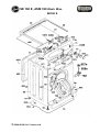
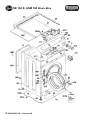
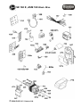
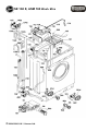
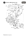
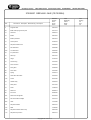
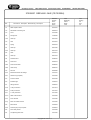
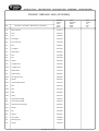
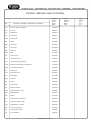
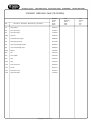
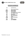
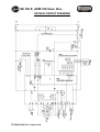
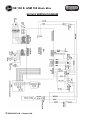
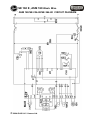
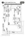
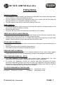
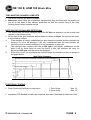
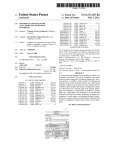
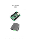
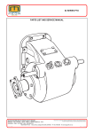
W.MACHINE/WASHER-DRYER
31000831 SE234-80
Service Manual
SE 160 E, ASM 160 Wash. M/cs
SE160 E
© 2004 GIAS U.K. / Hoover Ltd.
SE 160 E, ASM 160 Wash. M/cs
© 2004 GIAS U.K. / Hoover Ltd.
SE 160 E, ASM 160 Wash. M/cs
© 2004 GIAS U.K. / Hoover Ltd.
SE 160 E, ASM 160 Wash. M/cs
© 2004 GIAS U.K. / Hoover Ltd.
SE 160 E, ASM 160 Wash. M/cs
211
21211
© 2004 GIAS U.K. / Hoover Ltd.
31000831 SE234-80 0442 (12/10/2004)
Ref.
Descrizione - Description - Beschreibung - Descripcion
Ricambio
Part No.
Piece
E-Teil
Pieza
2
Programs disc
03841518
8a
Buffer with spring service pack
97917116
15
Cam disc
03850314
19
Button
03841445
24
Button protection
03841444
31
Control panel
40002149
32
Dispenser drawer front
04230676
48
R/H side frame
03940686
48a
L/H side frame
03940687
49
Top rear frame
03940685
51
Work top
03410167
60
Hinge
91700102
61
Counter ring
91601645
62
Door surround
91601647
63
Door glass
91600903
65
Door catch
91601655
66
Spring
91408713
67
Glass door with frame
91670644
73a
Screw
09031030
76
Cabinet assy
04230672
77
Rear panel
97911044
78
Socle
41006148
79
Rear foot
92606474
80
Front foot
92692300
94c
Filter knob with gasket
06015493
97d
Filt hous w/filter cartridge
91941772
99a
Hose
41010982
101
Dispenser drawer
03870775
103
Rack
41005935
109
Dispenser bottom section assy
03870708
110
Dispenser top section
03870774
Copyright 2011 Gias S.r.L.
Inizio
Beginning
Debut
Begin
Inicio
Fine
Ending
Fin
End
Fin
31000831 SE234-80 0442 (12/10/2004)
Ref.
Descrizione - Description - Beschreibung - Descripcion
Ricambio
Part No.
Piece
E-Teil
Pieza
111
Water injector nozzle
92149327
112
Distribution connecting rod
92884212
113
Lever
97910582
114
Driving lever
41000950
114a
Hose clip
92470061
116
Cam
06012915
118
Spring
92483148
131
Hose clip
92470020
131a
Hose clip
92470194
132
Hose
97910517
133
Hose clip
92470012
134
Solenoid valve
25686057
138
Drain hose
92693373
138a
Drain house elbow
92689587
138b
Hose clamp
92895051
142
Fill hose
92250869
151a
Motorized selector 30 settings
91201337
152f
Switch assy (Unipolar)
91201694
153
Pressure switch
28375052
155
Indicator light
91209510
157
Wiring harness
04660497
157d
7 Way connection
97911473
157e
6 Way connecton
97911481
157f
11 Way connecton
97911499
157m
Water valve harness
91201486
157n
Timer harness
91201360
157p
Motor to module harness
91201485
158
Mains block
91623678
161d
Drain/recycle pump complete
97922819
162
Door safety device
91201208
164
Anti jamming filter radio
91212795
Copyright 2011 Gias S.r.L.
Inizio
Beginning
Debut
Begin
Inicio
Fine
Ending
Fin
End
Fin
31000831 SE234-80 0442 (12/10/2004)
Ref.
Descrizione - Description - Beschreibung - Descripcion
Ricambio
Part No.
Piece
E-Teil
Pieza
178
Motor connector
27719213
202
Drum
04240181
203
Tub
97923565
204a
Front flange
04240184
205
Drum shaft assy
04150062
211
Bolt
97923474
215
Tub gasket
92131689
217
Seal retainer
92445600
219
Bolt
21446068
221
Nut
92424209
225a
Gasket
92445626
230
Tub gasket clip
91750458
230a
Tub gasket clip
90488603
232
Heater holder
97910301
242
Support spring.
92484492
242a
R/H support spring
92484484
244
Washer
92430206
244a
Counter weight washer
40001133
246
Bolt
92419472
246a
Bolt
97911507
246b
Slide
09078825
246c
Clamp
97910061
247
Upper balance weight
97910491
248
Lower balance weight
03940700
251a
Telescopic shock absorber
92484518
251c
Washer
97910509
251d
Nut
97915565
259
Support
92673961
271
Door gasket
41008852
272
Discharge pipe
41001597
273
Fill pipe
91620033
Copyright 2011 Gias S.r.L.
Inizio
Beginning
Debut
Begin
Inicio
Fine
Ending
Fin
End
Fin
31000831 SE234-80 0442 (12/10/2004)
Ref.
Descrizione - Description - Beschreibung - Descripcion
Ricambio
Part No.
Piece
E-Teil
Pieza
274
Pressure switch air chamber
06012804
275
5x8 hose
66655731
276
Steam hose
03860457
277
Hose spring
90386137
278a
Hose clip d44
92470137
286
Heater
91201546
287m
NTC probe
92743616
290
Drum pulley
92723824
292
Drive belt
92130442
292c
Clips
92473636
330
Screw x hinge
97917587
473
Commutator motor
41002725
479i
Coreboard 32K programmed
09200350
479m
Electronic control 32K not programmed
41003803
483a
Brush with brush holder
49000466
487
Special bolt
09183567
491c
Mains cable x UK
91200201
494
Red window
91611509
500a
Hose clip
06012880
526
Sleeve
91601654
535
Knob handle
03841449
547
Module protection
91601842
547a
Module protection cover
91601843
558
Support bracket
92884204
588
Siphon
41000762
602
Shock-absorb.conn.bracket
92898790
614
Therm.press.push b. supp.
03870756
618c
Unipolar NA+P.A. switch
90489683
632
Control support plate
91802090
643
Door handle assembly
91601653
734
Timer protection
03420083
Copyright 2011 Gias S.r.L.
Inizio
Beginning
Debut
Begin
Inicio
Fine
Ending
Fin
End
Fin
31000831 SE234-80 0442 (12/10/2004)
Ref.
Descrizione - Description - Beschreibung - Descripcion
Ricambio
Part No.
Piece
E-Teil
Pieza
797
Hinge plaque
92897347
806
Door upper hinge
41005451
807
Door lower hinge
41005452
828b
Tach.coil
49000464
831
Thermostat hole stopper
92898394
832
Discharge pipe circlip
09077298
833
Upper counterweight support
92898915
834
Lower counterweight supp.
92898923
835a
Magnet
49000465
839
Clip
92470384
840
Drum paddle
03870539
848
Plug
92943216
1000
Ring
97910459
1003
Door release link
90384405
1007
Tie rod
92401447
1019
Instruction for use
40002147
1068
Trade mark plate
41000597
Copyright 2011 Gias S.r.L.
Inizio
Beginning
Debut
Begin
Inicio
Fine
Ending
Fin
End
Fin
SE 160 E, ASM 160 Wash. M/cs
ELECTRIC DIAGRAM KEY
134
-
Cold Fill Valve
151
152F-1
152F-2
152F-3
153
155
161
162
164
286
287M
473
479
618C
-
Timer Selector Motor
Option Button
Option Button
Option Button
Low / High Pressure Switch
On / Off Pilot Lamp
Drain Pump
Door Micro-switch
Mains Suppressor
Heater
N.T.C. Thermostat
Motor
Control Module
On / Off Switch
© 2004 GIAS U.K. / Hoover Ltd.
SE 160 E, ASM 160 Wash. M/cs
SE160 E CIRCUIT DIAGRAM
© 2004 GIAS U.K. / Hoover Ltd.
SE 160 E, ASM 160 Wash. M/cs
SE160 E WIRING DIAGRAM
© 2004 GIAS U.K. / Hoover Ltd.
SE 160 E, ASM 160 Wash. M/cs
ASM 160/SE 234-80/SE 264-80 CIRCUIT DIAGRAM
© 2004 GIAS U.K. / Hoover Ltd.
SE 160 E, ASM 160 Wash. M/cs
ASM160 /SE 234-80/SE 264-80 WIRING DIAGRAM
© 2004 GIAS U.K. / Hoover Ltd.
SE 160 E, ASM 160 Wash. M/cs
Fitting Notes
WORKTOP REMOVAL
• The worktop is of a new design and features a removable rear support allowing access
to the machine by sliding the hardboard top off.
• The rear support is removed by undoing the three 7mm. screws, this will then allow the
worktop surface to be removed by sliding it to the rear.
• The side supports can then be removed by sliding to the rear.
BEZEL REMOVAL
• To remove the bezel, firstly remove the worktop side supports, allowing access to the
two screws holding the bezel in position.
• Remove the two screws.
• The bezel will then need to be eased up and pulled out of its seating.
TIMER AND CONTROL KNOB REMOVAL
• Once the bezel is removed, pull off the control knob and this will then reveal the timer
actuating cam, remove the 8 mm nut, remove the cam assy.
• Access can then be gained to the 2 x Phillips head screws securing timer to inner bezel
support. Remove the two screws and take the timer off the bezel.
OPTION SWITCH REMOVAL
• The option switch support assy can be removed by undoing the 5 screws attaching it to
the bezel.
• Remove the buttons from the switch being replaced.
• The switch can then be pushed through the support.
PRESSURE SWITCH REMOVAL
• The pressure switch is secured by a bracket attached to the inner metal support
underneath the timer and can be removed by a single screw attached to the bracket.
SOAP DISPENSER REMOVAL / SETUP
• The soap dispenser is serviceable and contains three compartments, the third
compartment being available to incorporate the use of fabric conditioner.
• To remove the dispenser, remove the worktop and bezel disconnect all hoses,
disconnect dispenser actuating arm from the top of the dispenser noting the setting of
the arrow on top of dispenser, remove the single phillips head screw from the top front
of bezel, the dispenser can then be removed complete.
TO SETUP DISPENSER ACTUATING ARM,
Program 2
Program 1 pointer at 1st notch
Program 5 Pointer at 3rd notch
Program 6
© 2004 GIAS U.K. / Hoover Ltd.
pointer at 2nd notch
pointer at 4th notch
PAGE 1
SE 160 E, ASM 160 Wash. M/cs
DOOR GASKET REMOVAL
• To remove the gasket assy firstly remove the plastic clamp band around the front of the
gasket. To remove the inner clamp band a 7mm. nut spinner and 7mm. open ended
spanner will be required. Re-fit gasket in reverse order taking care to ensure that the cut
out on the side of the gasket lines up with the hose assy (where used) situated at
approx. 9’o’ clock.
DOOR INTERLOCK REMOVAL
A BI-metal type interlock is fitted on all models.
• To gain access to the interlock remove the clamp band surrounding the tub shell gasket
and ease the front of the gasket off the shell.
• Remove the two screws holding the interlock and it can be removed from the door
aperture.
• Note the wiring connections before removing the original interlock.
• After servicing the door interlock make sure that the clamp band is replaced .
MOTOR ASSY REMOVAL
• To remove the motor firstly remove the non-adjustable elasticated belt, the motor can
then be removed by undoing the two 10m.m. self tapping bolts.
• Care must be taken when removing and refitting the motor.
• To prevent damage to the motor supports, place a block of wood at the rear of the motor
under the tacho assembly and tap the motor to gently ease it away from the mountings.
DRUM AND TUB REMOVAL
• Remove the Worktop.
• Open the door and undo the two screws holding the door & the hinge, lift away the door
assembly including the hinge.
• Remove the gasket clamp band ,release the gasket from the shell and push it through
into the cabinet.
• Remove the top weight assy, two 10mm. and one 13mm. securing bolts from tub assy.
• Remove timer assy and associated wiring, motor assy, thermostat, heater connections,
earth connection for drum bearing, sump hose and pecker assy.
• Carefully lay the machine on its right hand side (timer side) taking care to ensure that
the shell assy interior is protected with some hardboard.
• Remove the four 7mm. machined screws from the base of each suspension strut.
• The tub assy is now free to be carefully removed from the shell.
• Access to the lower tub weight is now available and is held in place by three 10mm.
bolts.
• The drum can now be accessed by removing 16 screws from the tub front,
• The tub front can be lifted away with the tub shell gasket attached.
• To remove the drum :Remove the drum pulley and the drum can be withdrawn from the
front of the tub,
• The drum may be very tight and require knocking out of the tub.
• Care must be taken to protect the drum shaft threads with a packing bolt.
© 2004 GIAS U.K. / Hoover Ltd.
PAGE 2
SE 160 E, ASM 160 Wash. M/cs
TUBS MUST BE CHANGED COMPLETE
• The drum bearings are not serviceable,
• Make sure when fitting the suspension dampers that they are fitted with the plastic rod
end on to the base of the cabinet, positioned so that the smooth face of the alloy
housing faces inward towards the tub.
NOTE ON OUT OF BALANCE DETECTION.
• The timers used on these machines have Out Of Balance detection on the module and
operate in the following way.
• At the start of the spin sequence as the machine ramps to 95rpm, the load on the motor
is monitored as follows.
1.
If the machine is heavily unbalanced the spin sequence restarts and the process can
continue for up to 12 attempts if still very unbalanced then the cam position will
cause the drum to remain stationary for the remainder of spin time.
2.
The machine also monitors the load at 650 rpm if still slightly unbalanced at this
point it will try three times to even the load;if it fails, the machine will carry on
spinning at 650 rpm until the end of the program.
3
If the drum is not out of balance the module allows the machine to spin as shown in
the graph below.
Ideal Spin Sequence
ELECTRICAL TESTING
•
Earth Continuity Earth pin on plug top to
•
Insulation CCP Bonded to Earth spin selected, door shut, Switched On Minimum 1MΩ
© 2004 GIAS U.K. / Hoover Ltd.
1. Door Hinge
2. Drum Inner
Max 1Ω
Max 1Ω
PAGE 3