1
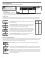
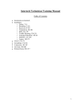
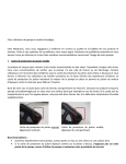
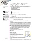
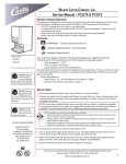
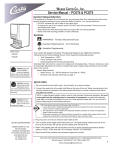
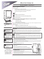
Wilbur Curtis Company, Inc.
Service Manual – CAFEOAT3
Important Safeguards/Conventions
This appliance is designed for commercial use. Any servicing other than cleaning and maintenance should be performed by an authorized service technician.
• Do NOT immerse the unit in water or any other liquid
• To reduce the risk of fire or electric shock, do NOT open top panel. No user serviceable parts inside.
• Keep hands and other items away from hot surfaces of unit during operation.
• Never clean with scouring powders or harsh chemicals.
Symbols:
WARNINGS – To help avoid personal injury
Important Notes/Cautions from the factory. Possible voiding of warranty.
Sanitation Requirements
Your Curtis Cafe Oat unit is Factory Pre-Set and Ready to Go… Right from the Box.
Following are the Factory Settings for your Cafe System:
Model
CAFEOAT3
• Tank Temperature = 190°F
• Flavor Controls= Set at 90%
• Dispensing Mode Set for Manual Dispensing
Generally there will never be a reason to change your programming. However, should you need to make slight adjustments to meet your
dispensing needs, programming instructions are provided later in this manual.
System Requirements:
• Water Source 20 – 90 PSI (Minimum Flow Rate of 1 GPM)
• Electrical: See attached schematic for standard model or visit www.wilburcurtis.com for your model.
Equipment to be installed to comply with applicable federal, state, or local plumbing/electrical codes having jurisdiction.
SETUP STEPS
WARNING HOT LIQUID,
Scalding may occur.
Avoid splashing.
The unit should be level (left to right and front to back) and located on a secure counter top. Connect a water line from the water filter to
the brewer.
NOTE: Some type of water filtration device must be used to maintain a trouble-free operation. (In areas with extremely hard water, we
suggest that a sedimentary and taste & odor filter be installed.) This will prolong the life of your dispensing system and improve the
product quality.
NSF International requires the following water connection:
CAUTION: Please use
this setup procedure
before attempting to use
this appliance. Failure to follow the
instructions can result in injury or the
voiding of the warranty.
CAUTION: DO NOT
connect this unit to hot
water. The inlet valve is
not rated for hot water.
WARNING TO AVOID
SCALDING, Do not
remove cup while product
is dispensing.
ISO 9001:2008
Wilbur Curtis Company
Montebello, CA 90640
Tel: (323) 837-2300
www.wilburcurtis.com
1.
2.
3.
A quick disconnect or additional coiled tubing (at least 2x the depth of the unit) so that the machine can be moved for cleaning underneath.
In some areas an approved backflow prevention device may be required between the CAFEOAT3 and the water supply.
Water pipe connections and fixtures directly connected to a potable water supply shall be sized, installed and maintained in accordance with federal, state, and local codes.
1. Connect a water line from your facility to the 1/4” flare water inlet fitting of the valve, behind the machine. Water volume going to the machine should be stable. Use tubing sized sufficiently to provide a minimum flow rate of one gallon per minute.
2. Plug the power cord into an electrical outlet rated at 20A.
3. Switch on the toggle switch, behind the unit, that runs power to the components in the machine. The display window and Stop/Wash
light on the front door will activate and the heating tank will start to fill.
4. Water in the heating tank will require about ½ hour to reach operating temperature (factory setting of 190°F). At this time the Ready LED will light.
5. Remove and fill the canisters with oatmeal mixes.
OPERATING INSTRUCTIONS
1. Select your flavor.
2. Place a cup on the tray beneath the spout of your selected flavor.
3. Press the dispensing button for this flavor and hold it down until cup has filled.
4. After filling, stir the oatmeal and then allow it to sit in the cup for a minute before eating.
FILL CANISTERS DAILY
1.
2.
3.
Open the front door to access the product canisters.
Removed the canisters from the unit for filling. Pull the canister towards you while
lifting slightly from it’s place on the canister shelf.
Return the canisters to their position within the machine. Align the gear socket behind
the canister with the gear on the auger motor.
FOR THE LATEST SPECIFICATIONS AND INFORMATION GO TO WWW.WILBURCURTIS.COM
1
Steps to Programming
Your Curtis Cafe System is Factory Pre‑Set for Optimum Performance.
WARNING HOT LIQUID, Scalding
may occur. Avoid splashing.
Place an empty container under the
dispensing nozzles while programming.
All programming is performed at the control panel
(illustration, right). The STOP/WASH BUTTON has several functions. This button is used to stop a Portion Control
dispense cycle. It is used to dispense hot water, and it is used to enter the programming functions.
Product % Ratio
This controls the amount of dry product that is metered from the hoppers. This can be programmed from 10% to 100% of the capacity of the
dispensing system. By counting number of flashes you can determine the product % ratio currently set for this dispense button (see table).
Enter Program Mode – Press and hold the STOP/WASH button for about ten [10] seconds
until all lights start blinking.
To program Product % Ratio – Select the product button, marked PUSH, that you wish to
change. Press and hold this PUSH button for approximately one second, then release. The
current setting will be indicated by the blinking light above the button.
To change the product throw – Press and hold the selected PUSH button until the light
starts to quick flash. Each quick flash increases the amount by 10%. Release the button when
the desired throw ratio is attained. After releasing the button, the slower blinking light will
resume. The new product ratio setting is indicated by counting the number of blinks. To exit the Powder Dispensing Mode, press one of the other PUSH buttons on the control
panel. This will set the product ratio and exit from the program mode.
Number of
Flashes Volume
1
10%
2
20%
3
30%
4
40%
5
50%
6
60%
7
70%
8
80%
9
90%
10
100%
Portion Control Dispensing Mode
This program adjustment allows you to setup the machine to automatically dispense a preset volume of oatmeal product. When the user makes
a PUSH button selection, the unit dispenses only the volume of product programmed by the Portion Control Dispensing Mode. By setting the
unit for Portion Control Dispensing, you have locked out the manual dispense feature.
Enter Program Mode – press and hold STOP/WASH for about ten [10] seconds until all lights start blinking.
To select & change the Portion Control Dispensing Volume – while in the programming mode, press and hold the
selected PUSH button until hot water starts flowing, then release. The timing starts when hot water begins to flow.
Stop & Exit – When the cup volume reaches 3/4 full, press the PUSH button once again to stop the dispensing. You
have now set the automatic dispense timing for this button and have exited the programming mode. Pressing the
dispense button now will provide only the product volume that was just set. To reset the timing, you must start again
by entering the programming mode.
2
Manual Dispensing Mode
This feature sets up the CAFEOAT unit to dispense product only as long as the user holds down the selected PUSH button. Once you stop
pressing the dispense button, product stops flowing. Setting the unit for Manual Dispense will turn off the Portion Control Dispense Mode.
Enter Program Mode – Press and hold STOP/WASH for about ten [10] seconds until all lights on the control panel
are blinking.
Set Manual Dispense – While you are in the programming mode, press and hold the selected PUSH button.
Hot water will start to flow.
Continue to hold down the PUSH button until the water stops flowing, then release the button.
Now the selected PUSH button is setup for the Manual Dispensing Mode. The control panel exits the programming
mode.
Confirm/Reset Temperature (Factory set at 190ºF)
These features allow you to check the heating tank temperature or change the temperature if desired. The temperature
in the tank is programmable from 80ºF, in 5 degree increments up to 140ºF, then temperature will jump 45 degrees to
185ºF, then resume 2 degree increments up to a maximum 204°F (see Temperature Settings table, right).
To Change Tank Temperature
Enter Program Mode – press and hold STOP/WASH for about ten [10] seconds until all
lights on the control panel are blinking.
Enter Temperature Program Mode. – Press and hold STOP/WASH for approximately one
[1] second, then release. The current setting will be indicated with the blinking light above the
STOP WASH button.
To Change Temperature – Press and hold the STOP/WASH button again. Each quick flash
increases the temperature. Release the STOP/WASH button when desired temperature is
reached. After releasing the button, the slow blinking light will resume. The new temperature
setting is indicated by counting the number of blinks.
To Set and Exit, press one of the PUSH buttons.
ERROR CODES
Curtis Cafe systems contain various safety features in the electronic circuitry that shut down the functions of the unit in the event of a system failure. Error
codes are signalled by the READY light blinking one of three patterns:
WATER LEVEL ERROR – 3 LONG AND 1 SHORT
When this code is seen on the control panel, there is a malfunction in the water level control system.
TEMPERATURE SENSOR ERROR – 3 LONG AND 2 SHORT
When this light pattern is flashing on the control panel there is a system failure with the heating tank.
COMMUNICATION ERROR – 3 LONG AND 3 SHORT
This flashing light pattern indicates a communication error between the switch panel on the door and
the power module.
3
Dump Valve Replacement
We recommend that you regulate the water flow in the valve ONLY when replacing a valve.
WARNING: As with all electrical equipment, caution must be taken to avoid electrical shock. Be
sure the power cord is disconnected before removing components. The following steps will also
involve working near hot surfaces.
I. Instructions for replacing a valve:
A. Shut off the water line running into the unit.
B. Disconnect the power cord or turn off the unit at the toggle switch behind the unit.
C. Drain approximately ½ to ¾ gallon of water from the tank to insure that the water level is below the
level of the valves. Remove the wires and water tubing from the defective valve and pull it from the
silicone fitting.
D. Before installing on the tank, make an initial adjustment with the valve off of the tank.
1. Loosen the screw on the metal guard. Rotate away from the adjustment screw (fig. 1.).
2. Carefully, turn flow adjustment screw clockwise all the way in (see figure 2.). Observe restrictor position . Do not overtighten.
3. Now turn the flow adjustment screw counter clockwise three [3] turns (or 1½ turns from the fully open position).
4. Replace the metal guard.
5. Install the valve on the tank, attaching wires and silicone tube. Press the valve fully into the fitting on the heating tank.
II. Dump valve, water flow adjustment:
The Water flow is preset to ensure optimum mixing and proper chamber rinsing. The valves currently installed on your unit have been set at the factory and should not require adjusting. The factory flow rate setting is 4 oz. of water in 10 seconds (or 0.4 oz./sec.).
Illustrated Parts List
ITEM
№
1
2
3
4
5
6
7
8
9
10
11
12
13
14
15
15A
16
17
18
19
PART
№
DESCRIPTION
WC-5853-102
WC-43062 *
WC-5502-01*
WC-3734 *
WC- 904-04*
WC-1438-101 *
WC- 521 *
WC-6291
WC-3765L*
WC-7389
CA-1111-06
CA-1168
WC-58142
CA-1036*
CA-1095
WC-66086**
CA-1011-05
WC-53136
WC-3504*
WC- 718
COVER, TOP HEATING TANK GEN USE
GASKET, TANK LID
KIT, PROBE WTR LVL W/FITTING, O’RING, NUT
DUMP VALVE 120V 12W
HEATING ELEMENT 1600W 120V W/JMNUT
SENSOR, TEMPERATURE TANK
SWITCH, #4680 VESSEL LIMIT
TANK COMPLETE, CAFE PC3
KIT, INLET VALVE REPAIR USE ON WC-826L
COVER, TOP CAFE PC3
CANISTER ASSY 4LB CAFEPC2/3/4
ELBOW, CANISTER 3-WAY
COVER, DUMP VALVE
GEAR, PLASTIC
CONNECTOR, ORIFICE WATER
ELBOW, DISPENSE CAFEOATS
BULKHEAD, WATER FITTING
TUBE, DISPENSE HOT WATER
LEG, ADJUSTABLE BLACK
TRANSFORMER, 120VAC-12VAC
** Used On Machines Built After 8/2012.
4
ITEM
№
20
21
22
23
24
25
26
27
28
29
30
31
32
33
34
35
36
37
38
PART
№
DESCRIPTION
WC- 782*
WC-37174*
CA-1135
WC-5310 *
WC-68219
WC-68218
WC- 722K
WC-39554
WC-66033
WC-66036-101
WC- 826L *
WC- 102*
WC-68211
WC-37266
WC-2627
WC-37365
WC-4394
CA-1136
WC-39872
CONTROL POWER MODULE CAFEPC’s 120V
KIT, GEAR MOTOR & GEAR
LATCH ASSEMBLY DOOR SIDE MOUNT
TUBING, 5/16” ID x 1/8” W SILICONE
COVER, BACK DOOR
DOOR, CAFEPC
PANEL, SW 120V CAFE PC3 (W/SMART CARD)
LABEL, CONTROL PANEL CAFEPC3
SCREEN, DRIP TRAY CAFE PC3
DRIP, TRAY ASSY CAFEOAT3
VALVE, INLET 1GPM 120V 10W
SWITCH, TOGGLE NON-LIT 25A 120/240VAC
COVER, SIDE LEFT CAFE3OAT
KIT, TANK OVERFLOW FITTING WITH BUSHING
BUSHING, CONICAL GENERAL USE
KIT, TANK INLET FITTING INCLUDES BUSHING
GUARD, SHOCK HEATING ELEMENT
HINGE, ASSY PLASTIC CAFEPC/SD2
LABEL, GRAPHIC ADHESIVE CURTIS
* Suggested Parts to Stock
Illustrated Parts List
1
2
33
3
8
4
34
5
36
6
35
7
10
9
11
12
37
13
14
32
30
15A
31
15
17
18
24
25
16
38
19
20
21
22
26
23
27
28
29
5
Electrical Diagram
1 PIN CONNECTOR PEN ASSIGNMENTS
PIN 1: 12V TRANS OMER
PIN 2: 12V TRANS ORMER
PIN 3: A TER LEVEL PRO E
PIN 4: V
5V
PIN 5: NOT USED
PIN 6: TEMPERATURE SENSOR
PIN 7: TEMPERATURE SENSOR
PIN 8: NOT USED
PIN 9: NOT USED
PIN 10: CA EPC3 E 3
PIN 11: NOT USED
PIN 12: DATA COMM
PIN 13: V
L
C
PIN 14: CHASSIS GROUND
12 PIN CONNECTOR PEN ASSIGNMENTS
PIN 1: 120VAC HOT
PIN 2: 120VAC HOT
PIN 3: DUMP VALVE #1
PIN 4: INLET VALVE
PIN 5: 120VAC NEUTRAL
PIN 6: NOT USED
PIN 7: GEAR MOTOR #1
PIN 8: DUMP VALVE #2
PIN 9: GEAR MOTOR #2
PIN 10: DUMP VALVE #3
PIN 11: GEAR MOTOR #3
PIN 12: NOT USED
PINCONNECTOR ASSIGNMENTS
PIN 1: V
5V
PIN 2: V
L
C
PIN 3: DATA COMM IRST
PIN 4: DATA COMM NE T
6
CHANGED THE "TOTAL POWER" (WAS) 1350 (IS) 1500 max.
CHANGED THE "TOTAL AMPS" (WAS) 12 (IS) 12.5.
Cleaning and Food Safety
Clean the CAFEOAT unit daily. Cleaning should be performed, not only to maintain a pleasant appearance but as a food safety discipline.
1. Switch off the unit at the power toggle switch, marked CONTROL, behind the unit.
2. Wipe all exterior surfaces with a damp cloth; removing any spills, dust or debris from the unit.
3. Remove the drip tray and louvered screen and wash out its contents. For hard to clean deposits, use a mild detergent solution.
4. Clean around the dispensing area, wiping with a nontoxic cleaner.
5. Turn on the unit at the power switch to return it to normal operation.
Food Safety is a discipline describing handling, preparation, and storage of food in ways that prevent foodborne illness. This includes a number
of routines that should be followed to avoid potentially severe health hazards.
The Basics: Clean, Separate, Cook and Chill
You can help prevent food poisoning from bacteria and viruses by following four simple steps when you prepare food:
CLEAN: Wash hands and surfaces often
SEPARATE: Don’t cross-contaminate!
COOK: Cook to proper temperature
CHILL: Refrigerate promptly
Rough-In Drawing
11.750”
20.250”
(29.8 cm)
(51.4 cm)
25.000”
(63.5 cm)
20.750”
(52.7 cm)
3.750”
(9.5 cm)
7
Product Warranty Information
The Wilbur Curtis Company certifies that its products are free from defects in material and workmanship under normal
use. The following limited warranties and conditions apply:
3 Years, Parts and Labor, from Original Date of Purchase on digital control boards.
2 Years, Parts, from Original Date of Purchase on all other electrical components, fittings and tubing.
1 Year, Labor, from Original Date of Purchase on all electrical components, fittings and tubing.
Additionally, the Wilbur Curtis Company warrants its Grinding Burrs for Forty (40) months from date of purchase or 40,000 pounds
of coffee, whichever comes first. Stainless Steel components are warranted for two (2) years from date of purchase against leaking
or pitting and replacement parts are warranted for ninety (90) days from date of purchase or for the remainder of the limited warranty
period of the equipment in which the component is installed.
All in-warranty service calls must have prior authorization. For Authorization, call the Technical Support Department at 1-800-9950417. Effective date of this policy is April 1, 2003.
Additional conditions may apply. Go to www.wilburcurtis.com to view the full product warranty information.
CONDITIONS & EXCEPTIONS
The warranty covers original equipment at time of purchase only. The Wilbur Curtis Company, Inc., assumes no responsibility for
substitute replacement parts installed on Curtis equipment that have not been purchased from the
Wilbur Curtis Company, Inc. The Wilbur Curtis Company will not accept any responsibility if the following conditions are not met. The
warranty does not cover and is void under the following circumstances:
1)
2)
3)
4)
5)
6)
7)
8)
9)
Improper operation of equipment: The equipment must be used for its designed and intended purpose and function.
Improper installation of equipment: This equipment must be installed by a professional technician and must comply with all local electrical, mechanical and plumbing codes.
Improper voltage: Equipment must be installed at the voltage stated on the serial plate supplied with this equipment.
Improper water supply: This includes, but is not limited to, excessive or low water pressure, and inadequate or fluctuating water flow rate.
Adjustments and cleaning: The resetting of safety thermostats and circuit breakers, programming and temperature
adjustments are the responsibility of the equipment owner. The owner is responsible for proper cleaning and regular maintenance of this equipment.
Damaged in transit: Equipment damaged in transit is the responsibility of the freight company and a claim should be made with the carrier.
Abuse or neglect (including failure to periodically clean or remove lime accumulations): Manufacturer is not responsible for variation in equipment operation due to excessive lime or local water conditions. The equipment must be maintained according to the manufacturer’s recommendations.
Replacement of items subject to normal use and wear: This shall include, but is not limited to, light bulbs, shear disks, “0” rings, gaskets, silicone tube, canister assemblies, whipper chambers and plates, mixing bowls, agitation assemblies and whipper propellers.
Repairs and/or Replacements are subject to our decision that the workmanship or parts were faulty and the defects showed up under normal use. All labor shall be performed during regular working hours. Overtime charges are the responsibility of the owner. Charges incurred by delays, waiting time, or operating restrictions that hinder the service technician’s ability to perform service is the responsibility of the owner of the equipment. This includes institutional and correctional facilities.
The Wilbur Curtis Company will allow up to 100 miles, round trip, per in-warranty service call.
RETURN MERCHANDISE AUTHORIZATION: All claims under this warranty must be submitted to the Wilbur Curtis Company
Technical Support Department prior to performing any repair work or return of this equipment to the factory. All returned equipment must be repackaged properly in the original carton. No units will be accepted if they are damaged in transit due to improper
packaging. NO UNITS OR PARTS WILL BE ACCEPTED WITHOUT A RETURN MERCHANDISE AUTHORIZATION (RMA). RMA
NUMBER MUST BE MARKED ON THE CARTON OR SHIPPING LABEL. All in-warranty service calls must be performed by an
authorized service agent. Call the Wilbur Curtis Technical Support Department to find an agent near you.
EAR 10755 . ECN 14278 . 7/25/12@10.5
EAR 9303.ECN 12979. 2/24/11@13.5
ear 8972 . ecn 12722 . 11/4/10WILBUR
@ 8.9
CURTIS CO., INC.
ECN12607 . 9/16/10 @ 15.3 6913 Acco St., Montebello, CA 90640-5403 USA
ear 8671 . edr 7275 . 7/30/10 @ 15.5
Phone: 800/421-6150
Fax: 323-837-2410
Technical Support Phone: 800/995-0417 (M-F 5:30A - 4:00P PST)
Web Site: www.wilburcurtis.com
E-Mail: techsupport@wilburcurtis.com
FOR THE LATEST SPECIFICATION INFORMATION GO TO WWW.WILBURCURTIS.COM
8
Printed in U.S.A. 7/2012 . F-3758 rev D