1
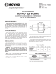
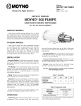
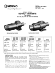
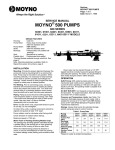
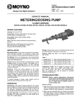
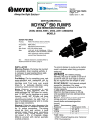
Section:
®
MOYNO 500 PUMPS
Page: 1 of 4
Date: March 1, 1998
SERVICE MANUAL
MOYNO® 500 PUMPS
300 Series Motorized
35650, 35651, 35652, 36750, 36751, and 36752 Model
DESIGN FEATURES
Cast iron/316 SS
Housing:
Pump Rotor: AISI 416 stainless steel/ANSI 316 SS
Pump Stator: NBR
NBR (Nitrile)
Seal:
Motor Shaft: Mechanical (carbon/ceramic)
3 phase; 1-1/2 HP, 208/230/460V for Models
Motor:
35650 and 35651; 2 HP, 230/460V for Models
36751 and 36750; 1 phase; 1-1/2 HP, 115/230V
for Model 35652; 1 phase; 2 HP, 115/230V for
Model 36752.60 Hertz, 1725 rpm, totally enclosed
Note:
Alternate elastomers available. Refer to Repair/ Conversion
Kit Numbers, page 4.
INSTALLATION
Mounting Position. Pump may be mounted in any
position. When mounting vertically, it is necessary to
keep bearings above seals to prevent possible seal
leakage into bearings.
Pre-Wetting. Prior to connecting pump, wet pump
elements and mechanical seal by adding fluid to be
pumped into suction and discharge ports. Turn pump
over several times in a clockwise direction to work
fluid into pump elements.
Piping. Piping to pump should be self-supporting to
avoid excessive strain on pump housings. See Table
1 for suction and discharge port sizes of each pump
model.
Use pipe “dope” or tape to facilitate disassembly and
to provide seal on pipe connections.
Electrical. Follow the wiring diagram on the motor
nameplate or inside the terminal box for the proper
connections. The wiring should be direct and conform
to local electrical codes. Check power connections for
proper voltage. Voltage variations must not exceed +
10% of nameplate voltage. Motors do not have
overload protection.
To prevent damage to pump, pump rotation must be
clockwise when facing pump from motor end.
OPERATION
Self-Priming. With wetted pumping elements, the
pump is capable of 25 ft. suction lift with pipe size
equal to port size. Be sure suction lines are air tight or
pump will not self-prime.
DO NOT RUN DRY. Unit depends on liquid pumped
for lubrication. For proper lubrication, flow rate should
be at least 10% of rated capacity.
Pressure and Temperature Limits. See Table 1 for
maximum discharge pressure of each model. Unit is
suitable for service at temperatures shown in Table 2.
Storage. Always drain pump for extended storage
periods by removing bottom drain plug. To drain
Model 36750, 36751 and 36752 remove suction
housing bolts and loosen suction housing.
Caution: Suction pressure should never be
greater than discharge pressure.
Pump Model
Table 1. Pump Data
356
Suction Port
(NPT)
Discharge Port
(NPT)
Voltage Rating
(VAC)
1-1/2
2
1-1/4
1-1/4
See Motor Name Plate
For Voltage Ratings
See Motor Name Plate
For Voltage Ratings
50
50
5 x CP
specific gravity
(approximate)
Discharge Pressure
(psig) (maximum)
NOTE: SSU =
367
Table 2. Temperature Limits
Elastomer
Temperature Limits
*NBR
10°-160°F
*EPDM
10°-210°F
*FPM
10°-240°F
*NBR = Nitrile
EPDM = Ethylene-Propylene-Diene Terpolymer
FPM = Fluoroelastomer
Page 2
TROUBLE SHOOTING
PUMP DISASSEMBLY
WARNING: Before
making
adjustments,
disconnect
power
source
and
thoroughly bleed pressure from
system. Failure to do so could result
in electric shock or serious bodily
harm.
WARNING: Before
disassembling
pump,
disconnect
power
source
and
thoroughly bleed pressure from
system. Failure to do so could result
in electric shock or serious bodily
harm.
1. Disconnect power source.
2. Remove suction and discharge piping.
3. Remove screws (112) holding suction housing (2)
to discharge housing (1). Remove suction housing
(2) and stator (21).
4. Rotor (22) can be detached from flexible joint (24)
by using a punch to remove rotor pin (45). Support
joint when removing pin.
5. Flexible joint (24) can be removed from motor
shaft by using a punch through the discharge port
to remove shaft pin (46).
6. Carefully slide mechanical seal (69) off motor
shaft.
7. Remove discharge housing (1) from motor (70) by
removing screws (112A and 112C) and washers
(215).
8. Carefully pry seal seat out of discharge housing
(1). If any part of mechanical seal (69) is worn or
broken, the complete assembly should be
replaced. Seal components are matched parts and
not interchangeable.
9. Remove slinger ring (77).
Failure To Pump.
1. Motor will not start: Check power supply. Voltage
must be ± 10% of nameplate rating when motor is
in locked rotor condition.
2. Motor runs and thermally kicks out: Check for
excessive pressure. Increase ventilation to motor.
Do not use less than #14 wire size.
3. Stator torn; possible excessive pressure: Replace
stator, check pressure at discharge port.
4. Flexible joint broken; possible excessive pressure:
Replace joint, check pressure at discharge port.
5. Wrong rotation: Rotation must be clockwise when
facing pump from motor end. Reverse the
connections of any two line leads to the motor.
6. Excessive suction lift or vacuum.
Pump Overloads.
1. Excessive discharge pressure: Check pressure at
discharge port for maximum ratings given in Table
2. Fluid viscosity too high: Limit fluid viscosity to 100
CP or 500 SSU.
Noisy Operation.
1. Excessive suction lift or vacuum: Maximum suction
2.
3.
4.
5.
lift is 25 feet for water.
Suction line too small: Check pipe size. Be sure
lines are free from obstructions.
Pump cavitates: Pump speed is 1725 rpm.
Viscosity of fluid should not exceed 100 CP or 500
SSU.
Flexible joint worn: Replace joint. Check pressure
at discharge port.
Insufficient mounting: Mount to be secure to a firm
base. Vibration induced noise can be reduced by
using mount pads and short sections of hose on
suction and discharge ports.
Seal Leakage.
1. Leakage at startup: If leakage is slight, allow pump
to run several hours to let faces run in.
2. Persistent seal leakage: Faces may be cracked
from freezing or thermal shock. Replace seal.
Pump Will Not Prime.
1. Air leak on suction side: Check pipe connections.
PUMP ASSEMBLY
1. Replace slinger ring (77).
2. Attach discharge housing (1) to motor (70) using
lock washers (215) and body screws (112A).
3. Install mechanical seal (69) using the following
procedures:
a. Clean and oil sealing faces using light oil (not
grease).
Caution: Do not use oil on EPDM parts.
Substitute glycerin or soap and water.
b. Oil the outer surface of seal seat, and push
assembly over motor shaft into the bore of the
discharge housing (1) seating it firmly and
squarely.
c. After cleaning and oiling the shaft, slide the
seal body along the shaft until it meets the seal
seat.
d. Install seal spring and spring retainer on shaft.
4. On Model 367, position seal spacer (69A) on
motor shaft with slots away from seal (69).
5. Pin flexible joint (24) to motor shaft with shaft pin
(46) using a punch through the discharge port.
6. Pin rotor (22) to flexible joint using rotor pin (45).
Support joint while installing pin.
7. Slide stator (21) on rotor (22) carefully locating
stator flange in housing groove.
8. Secure stator (21) and suction housing (2) to
discharge housing (1) using screws (112).
9.
Proceed as in installation instructions.
Page 3
Page 4
PARTS LIST
Item
Description
No.
1
Discharge Housing
2
Suction Housing
*21
Stator
*22
Rotor
24
Flexible Joint
*45
Rotor Pin
*46
Motor Pin
*69
Mechanical Seal
69A
Seal Spacer
70
Motor
72
Motor Support
77
Slinger Ring
103
Nuts (2 req.)
112
Screw, Hex Hd
112A
Screw, Hex Hd (4 req.)
112B
Screw, Hex Hd (2 req.)
215
Lock Washer
215A
Lock Washer (4 req.)
261
Pipe Plug
* Recommended spare parts
Pump Model Numbers
35650
35651
350-0632-007
350-0489-000
320-6392-015
330-7845-003
35652
36750
36751
36752
350-0632-000
350-0280-000
340-3505-120
320-6392-000
320-1618-000
320-4069-003
320-4069-005
320-3945-000
350-0632-007
350-0489-000
340-0951-000
350-0302-000
340-0951-007
350-0302-007
330-2042-000
330-3077-000
330-7845-000
320-4446-000
330-8054-002
340-0951-007
350-0302-007
340-3506-120
330-3077-000
320-1749-000
320-4439-002
320-4439-001
320-1750-000
320-1737-000
330-2802-004
300-2802-001
330-8053-004
320-4431-000
320-6385-000
614-0010-111 (3/8-16)
619-1530-161 (3/8-16 x 1) (4 req.)
619-1530-161 (3/8-16 x 1)
320-6918-000 (3/8-16 x 1-3/4)
623-0010-411 (3/8) (4 req.)
623-0010-411 (3/8)
610-0120-011 (1/8 NPT)
619-1530-161 (3/8-16 x 1) (6 req.)
619-1550-161 (1/2-13 x 1)
623-0010-411 (3/8) (6 req.)
623-0010-431 (1/2)
REPAIR/CONVERSION KIT NUMBERS (For cast iron pumps only)
Item
No
–
21
24
69
46
45
Description
Kit No.
•
Stator
•
Joint
•
Seal
•
Pin (Motor)
•
Pin (Rotor)
Model 35651
NBR
EPDM
311-9123-000
340-3505-120
320-1618-000
320-3945-000
FPM
311-9125-000
311-9126-000
340-3505-320
340-3505-520
320-6508-000
320-6509-000
320-6380-000
320-6510-000
320-4069-005
320-4069-003
Model 36751
NBR
EPDM
311-9060-000
340-3506-120
320-1749-000
320-1750-000
FPM
311-9036-000
311-9124-000
340-3506-320
340-3506-520
320-6378-000
320-6515-000
320-6390-000
320-6517-000
320-4439-001
320-4439-002
*NBR = Nitrile
EPDM = Ethylene-Propylne-Diene Terpolymer
FPM = Fluoroelastomer
ABRASION RESISTANT SEALS
Elastomer
NBR
EPDM
FPM
Models
356
320-6505-000
320-6506-000
320-6507-000
367
320-6511-000
320-6512-000
320-6513-000
© 1999 by Moyno, Inc.
® Moyno is a registered trademark of Moyno Inc.
Printed in U.S.A.