1
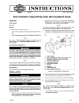
-J03929
REV. 2006-02-22
BILLET HEADLAMP WITH SHORT/TALL MOUNTS
GENERAL
REMOVAL
Kit Number
Remove Headlamp and Mounting Bracket for Softail
Models
68593-06, 69851-06
Models
Kit 68593-06 is a 5-3/4 inch headlamp and kit 69851-06 is a
4-1/2 inch headlamp. Both kits will fit the models listed in Table
1.
To prevent accidental vehicle start-up, which could cause
death or serious injury, disconnect negative (-) battery
cable before proceeding. (00048a)
Table 1. Short and Tall Mount Kits
1.
Disconnect negative (-) battery cable.
Kits
Models
2.
Remove fuel tank. Refer to FUEL TANK in Service Manual.
Short Mount Kit 68595-06
1984-1999 FXSTC, 1998Later FXST/B, and 2000-Later
FXSTD;
1994-2005 FXDWG
3.
Disconnect 4-place headlamp connector [38] from main
wire harness. Headlamp connector is located under fuel
tank on left side.
Tall Mount Kit 69611-06
1996-Later XL 1200C and
1998-Later XL 883C;
All 2006 Dyna Models;
1999-2000 FXR2/3/4
is01835
8
4
3
Additional Parts Required
This kit also requires the separate purchase of a Short or Tall
Mounting Kit 68595-06 or 69611-06 for your model motorcycle,
and can be purchased from a Harley-Davidson dealer.
5
6
The rider's safety depends upon the correct installation
of this kit. Use the appropriate service manual procedures.
If the procedure is not within your capabilities or you do
not have the correct tools, have a Harley-Davidson dealer
perform the installation. Improper installation of this kit
could result in death or serious injury. (00333a)
NOTE
This instruction sheet references Service Manual information.
A Service Manual for your model motorcycle is required for
this installation and is available from a Harley-Davidson dealer.
Kit Contents
See Figure 21,Table 2 and Figure 22, Table 3.
5
7
2
1
1.
2.
3.
4.
5.
6.
7.
8.
Screw
Washer
Nut
Lockwasher
Washer (2)
Screw
Mounting block
Headlamp assembly
Figure 1. Softail and Dyna Headlamp Assembly with Mount
(except FXSTD)
NOTE
All Softails (except FXSTD) complete steps 4 through 6. For
FXSTD models complete steps 7 through 9.
-J03929
Many Harley-Davidson® Parts & Accessories are made of plastics and metals which can be recycled.
Please dispose of materials responsibly.
1 of 10
4.
5.
All Softails (except FXSTD): See Figure 1. Remove screw
(1) and washer (2) from stem and bracket. Discard screw
but save washer for later use.
is01750
1
Remove and discard mounting block (7) and headlamp
assembly (8).
6.
FXSTD models: See Figure 2. Remove screw (1) and
washer (2) from stem and bracket. Save screw and washer
for later use.
7.
Remove and discard nut (3), washers (4), and screw (5).
8.
Remove and discard mounting block (6) and headlamp
assembly (7).
2
is01838
1. Cable strap
2. Wire harness
7
Figure 3. Dyna Service Loop (2005-Earlier)
4.
6
3
4
4
5
2005-Earlier FXDWG: See Figures 3 and 4. Remove plug
on right side of top frame tube. At service loop, remove
cable clip and push wire harness into top frame tube. Pull
connector out from hole on right side of tube.
2006-Later FXD: See Figure 5. Remove cover under top
frame tube, then pull connector out from opening under
tube.
5.
2
1
1.
2.
3.
4.
5.
6.
7.
Disconnect 4-place headlamp connector [38] from main
wire harness.
is01765
1
Screw
Washer
Acorn nut
Washer (2)
Screw
Mounting block
Headlamp assembly
Figure 2. FXSTD Headlamp Assembly with Mount
2
Remove Headlamp and Mounting Bracket for Dyna
Models
1.
Remove seat following the instructions in the Service
Manual.
2.
Disconnect negative (-) battery cable.
3.
Remove fuel tank. Refer to FUEL TANK in Service Manual.
-J03929
1. Frame tube
2. Plug
Figure 4. Dyna Top Frame Tube (2005-Earlier)
2 of 10
is01775
is01839
1
7
3,4
5
4
3
6
2
1,2
1. Frame tube
2. Cover
3. Plug
1.
2.
3.
4.
5.
6.
7.
Figure 5. Dyna Top Frame Tube (2006-Later)
6.
See Figure 1. Remove screw (1) and washer (2) from stem
and bracket. 2005-Earlier FXDWG: Discard screw but
save washer for later use. 2006-Later FXD: Save screw
and washer for later use.
7.
Remove and discard nut (3), washers (4), and screw (5).
8.
Remove and discard mounting block (6) and headlamp
assembly (7).
Screw
Washer
Nut
Washer (2)
Screw
Mounting block
Headlamp assembly
Figure 6. Sportster Headlamp Assembly with Mount
Remove Headlamp and Mounting Bracket for FXR
Models
Remove Headlamp and Mounting Bracket for
Sportster Models
1.
Remove seat following the instructions in the Service
Manual.
1.
Remove seat following the instructions in the Service
Manual.
2.
Disconnect negative (-) battery cable.
3.
Remove fuel tank. Refer to FUEL TANK in Service Manual.
2.
2003-Earlier: Disconnect negative (-) battery cable.
4.
Disconnect 4-place headlamp connector [38] from main
wire harness. Headlamp connector is located under fuel
tank on left side.
2004-Later: Remove maxi-fuse. Refer to MAXI-FUSE in
Service Manual.
3.
Remove fuel tank. Refer to FUEL TANK in Service Manual.
5.
4.
Disconnect 4-place headlamp connector [38] from main
wire harness. Headlamp connector is located under fuel
tank.
See Figure 7. Remove screw (1) and washer (2) from stem
and bracket. Save screw and washer for later use.
6.
Remove and discard nut (3), washers (4), and screw (5).
7.
Remove and discard mounting block (6) and headlamp
assembly (7).
5.
See Figure 6. Remove screw (1) and washer (2) from stem
and bracket. Save screw and washer for later use.
6.
Remove and discard nut (3), washers (4), and screw (5).
7.
Remove and discard mounting block (6) and headlamp
assembly (7).
-J03929
3 of 10
is01840
is01853
7
4
3
4
8
9
4
6
5
5
6
3
7
6
2
1
1.
2.
3.
4.
5.
6.
7.
2
1
Screw
Washer
Nut
Washer (2)
Screw
Mounting block
Headlamp assembly
1.
2.
3.
4.
5.
6.
7.
8.
9.
Figure 7. FXR Headlamp Assembly with Mount
INSTALLATION
Install Billet Headlamp with Short Mount
1.
2.
Softail and 1994-2005 FXDWG Models: See Figure 8.
Loosely install vertical adjusting screw (1) from kit and
washer (2) previously saved.
Screw
Washer
Mounting block, short
Headlamp assembly
Screw
Washer (2)
Lockwasher
Acorn nut
Mounting block, tall
Figure 8. Billet Headlamp Assembly with Short/Tall Mounts
Install Billet Headlamp with Tall Mount
1.
2000-Later FXSTD Models: See Figure 8. Loosely install
vertical adjusting screw (1) and washer (2) previously
saved.
See Table 1 and Figure 8. Loosely install vertical adjusting
screw (1) and washer (2) previously saved.
2.
Loosely install mounting block (3) and billet headlamp (4)
using horizontal adjusting screw (5), washers (6), lockwasher (7), and acorn nut (8).
Loosely install mounting block (9) and billet headlamp (4)
using horizontal adjusting screw (5), washers (6), lockwasher (7), and acorn nut (8).
3.
Check headlamp for proper height and lateral alignment.
Refer to Headlamp Alignment section in Instruction Sheet.
Connect Headlamp Wiring
Models With 4-Place Amp Multilock Connector:
-J03929
1.
Locate main harness pin housing.
2.
Insert socket housing of billet headlamp into pin housing
of main harness.
4 of 10
is01846
is01848
2
1
5
4
3
3
1
2
1.
2.
3.
4.
5.
4
1.
2.
3.
4.
Black ground wire
Bulb connector
Wire from connector to terminal
Ring terminal
Black jacket
Headlamp wire harness
Socket housing
Headlamp wires (3)
Bulb connector
Figure 10. Remove Black Jacket, Socket Housing, and
Strip Wires
Figure 9. Clip Black Ground Wire
9.
Models Without 4-Place Amp Multilock Connector:
Older chassis ground models, complete steps 1 and 2.
1.
See Figure 9. Clip black ground wire (1) inside new billet
headlamp close to the bulb connector (2). Refer to
REPLACE LAMP ASSEMBLY AND BULB for procedures
to disassemble billet headlamp.
NOTE
There are two black wires exiting the bulb. Be careful not to
clip the wire that is grounded to the internal housing with ring
terminal.
2.
Pull the long black wire out of the sleeving and discard.
3.
See Figure 10. Remove 1-1/2 inch (38.1 mm) of black
jacket (1) at a convenient location from headlamp wire
harness (2).
4.
Using wire cutters, remove the headlamp socket housing
(3).
NOTE
Use care not to cut the insulation on the three wires inside the
headlamp wire harness.
5.
Butt splice wires of billet headlamp to wires of main harness. Also refer to SEALED BUTT SPLICE CONNECTORS in Service Manual.
6.
Strip 3/8-inch (9.5 mm) of insulation off the ends of the
headlamp wires.
7.
See Figure 11. Insert headlamp wires into butt splice
connector until the stripped ends are housed inside the
metal insert (1).
8.
Crimp the wires (2) within the connector using suitable
crimping tool.
-J03929
Repeat steps on other side of butt splice connector for
main harness wires.
NOTE
Stagger the spices so that the butt splice connectors are
spaced at different positions along the length of the wires.
is01851
1
2
3
1. Metal insert
2. Crimp wire ends
3. Melted sealant after heating/cooling
Figure 11. Install Sealed Butt Splice Connectors
5 of 10
Be sure to follow manufacturer's instructions when using
the UltraTorch UT-100 or any other radiant heating device.
Failure to follow manufacturer's instructions can cause a
fire, which could result in death or serious injury. (00335a)
•
6.
Stand motorcycle upright with both tires resting on floor,
and with front wheel held in straight alignment (directly
forward).
7.
Sotail and Dyna Models: Turn ignition switch to ON position.
Sportster Models: Turn ignition/light switch to IGNITION
position.
Avoid directing heat toward any fuel system component.
Extreme heat can cause fuel ignition/explosion resulting
in death or serious injury.
•
Avoid directing heat toward any electrical system component other than the connectors on which heat shrink
work is being performed.
•
Always keep hands away from tool tip area and heat shrink
attachment.
FXR Models: Turn ignition/light switch to IGNITION position.
8.
See Figure 13. Set handlebar headlamp switch to high
beam position.
9.
Check light beam for alignment as follows:
10. Using the UltraTorch UT-100 (39969) or other suitable
radiant heating device, heat the crimped splice to encapsulate the butt splice connection. Apply heat from the
center of the crimp out to each end until the meltable
sealant exudes out both ends of the connector.
11. Heat the center of the butt splice (3) until the crimp
indentations disappear and the tubing assumes a smooth
cylindrical appearance.
a.
The main beam, which is a broad, flat pattern of light,
should be centered equally above and below the
horizontal line.
b.
The main beam of light should also be directed
straight ahead. Properly adjusted headlamps project
an equal area of light to right and left of center.
10. Tighten vertical adjusting screw and horizontal adjusting
nut to 25-30 ft-lbs (33.9-40.7 Nm).
is01858
12. Slide section of black jacket previously removed over butt
spliced wires and secure with clips.
Headlamp Alignment
The automatic-on headlamp feature provides increased
visibility of the rider to other motorists. Be sure headlamp
is on at all times. Poor visibility of rider to other motorists
can result in death or serious injury. (00030b)
1.
Verify correct front and rear tire pressure. Refer to TIRES
AND WHEELS in Service Manual.
2.
Place motorcycle on level floor (or pavement) in an area
with minimum light.
3.
Position motorcycle 25 ft (7.6 m) away from a screen or
wall. Measure the distance from directly below the front
axle to the base of the screen/wall.
4.
See Figure 12, Letter (A). Draw a horizontal line 35 inches
(0.9 m) above floor on screen wall.
Figure 13. High Beam Setting
Final Assembly
Softail and FXR Models
1.
Install fuel tank. Refer to FUEL TANK in Service Manual.
2.
Connect negative (-) battery cable.
Dyna Models
is01856
A
Figure 12. Headlamp Alignment
5.
1.
Install fuel tank. Refer to FUEL TANK in Service Manual.
2.
Install seat following the instructions in the Service Manual.
3.
Connect negative (-) battery cable.
FXR Models
1.
Install fuel tank. Refer to FUEL TANK in Service Manual.
2.
2003-Earlier models: Connect negative (-) battery cable.
3.
2004-Later models: Install maxi-fuse. Refer to MAXI-FUSE
in Service Manual.
Load vehicle with rider, passenger (if normally present)
and any cargo. Weight will compress vehicle suspension
slightly.
-J03929
6 of 10
REPLACE LENS ASSEMBLY AND BULB
NOTE
You can also use latex gloves to remove/install the chrome
trim ring. This will enable you to grip the chrome trim ring and
will not mark the finish.
When replacement is required, use only the specified
sealed beam unit or bulb, available from a Harley-Davidson
dealer. An improper wattage sealed beam or bulb, can
cause charging system problems. (00209a)
is01862
Never touch the quartz bulb. Fingerprints will etch the
glass and decrease bulb life. Grab the bulb with paper or
a clean, dry cloth. Failure to do so could result in bulb
damage. (00210a)
Handle bulb carefully and wear eye protection. Bulb contains gas under pressure, which, if not handled carefully,
could cause serious eye injury. (00062b)
NOTE
You do not need to remove billet headlamp from motorcycle
to replace lamp assembly and bulb.
Figure 15. Place Two-Sided Tape on Chrome Trim Ring
is01867
Disassembly
1.
All models (except 2004-Later Sportster): Disconnect
negative (-) battery cable.
2004-Later Sportster models: Remove maxi-fuse. Refer
to MAXI-FUSE in Service Manual.
2.
Using a 50/50 isopropyl alcohol/water solution, thoroughly
clean the billet headlamp and surface of the chrome trim
ring. Let dry completely.
3.
See Figure 14. Using 1/16-inch allen wrench, remove outer
set screw at bottom of headlamp shell.
is01863
Figure 16. Chrome Trim Ring (two-sided tape shown)
5.
See Figure 16. Place fingers on two-sided tape and
remove chrome trim ring (rotate counterclockwise) and Oring.
6.
See Figure 17. Using service tool, remove inner ring (rotate
counterclockwise) and rubber O-ring.
7.
See Figure 18. Unplug lamp assembly (1) from bulb connector (2) and remove from shell.
Figure 14. Allen Wrench and Outer Set Screw
4.
See Figure 15. Cut three 1/4 x 1-inch strips of two-sided
tape and place at equal distance around the chrome trim
ring.
-J03929
7 of 10
is01868
4.
See Figure 18. Plug lamp assembly (1) into wire harness
connector (2). Gently press lamp assembly into position
inside headlamp shell.
5.
See Figure 17. Using service tool, install inner ring (rotate
clockwise) and rubber O-ring. Use care when installing
ring to ensure proper threading into headlamp shell.
6.
See Figure 16. Install chrome trim ring (rotate clockwise)
and rubber O-ring. Remove strips of two-sided tape from
ring if used. Use care when installing ring to ensure proper
threading into headlamp shell.
7.
See Figure 14. Using 1/16-inch allen wrench, install outer
set screw at bottom of headlamp shell.
is01870
2
Figure 17. Service Tool and Inner Ring
3
1
is01869
3
1
2
1. Rubber boot
2. Lens assembly and bulb
3. Retaining clip
Figure 19. Lens Assembly, Retaining Clip, and Rubber
Boot
1. Lamp assembly
2. Bulb connector
3. Headlamp shell
is01871
Figure 18. Lamp Assembly and Bulb Connector
8.
See Figure 19. Remove rubber boot (1) from back of lens
assembly and bulb (2).
9.
Press ends of retaining clip (3) to unhook from notched
retaining post, then pivot retaining clip back.
10. See Figure 20. Remove bulb (1) from lens assembly (2).
Assembly
1.
See Figure 20. Fit replacement bulb (1) into lens assembly
(2).
2.
See Figure 19. Pivot the retaining clip (3) over the bulb
and press the ends into the retaining post.
3.
Install rubber boot (1) into back of lens assembly (2).
2
1
1. Bulb
2. Lens Assembly
Figure 20. Lens Assembly and Bulb
-J03929
8 of 10
SERVICE PARTS
is01908
8
7
6
9
10
4
5
11
14
16
13
15
2
14
12
17
15
3
1
Figure 21. Service Parts: 5-3/4 Inch Billet Headlamp With Short/Tall Mounts
Table 2. Service Parts: 5-3/4 Inch Billet Headlamp With Short/Tall Mounts
Kit
5-3/4 Inch Billet
Headlamp
68593-06
Short Mount Kit
68595-06
Tall Mount Kit
69611-06
-J03929
Item
Description (Quantity)
Part Number
1
Chrome trim ring
Not Sold Separately
2
Service tool, inner ring
94950-06
3
Inner ring
Not Sold Separately
4
Lens Assembly
69668-06
5
Bulb, dual filament 12V 60/55W H4
68329-03
6
Retaining clip
Not Sold Separately
7
Rubber boot
Not Sold Separately
8
Headlamp shell, chrome
Not Sold Separately
9
Headlamp wiring
Not Sold Separately
10
Set screw, #6-32 x 1/8 in. (outer trim ring)
Not Sold Separately
11
Set screw, #6-32 x 3/16 in. (nesting ring)
Not Sold Separately
12
Billet headlamp mount, short
Not Sold Separately
13
Capscrew, hex hd 3/8-16 x 1-3/4 in. (2) (chrome); FXSTD models use
quantity of one.
94237-91T
14
Washer, flat 3/8 in (2) (chrome)
94067-90T
15
Washer, lock 3/8 in (chrome)
94082-90T
16
Nut, acorn 3/8-16 (chrome)
94008-90T
17
Billet headlamp mount, tall
Not Sold Separately
Note: This kit also includes item 13 (quantity of one) and items 14 through 16.
9 of 10
is01908
8
7
6
9
10
4
5
11
14
16
13
15
2
14
12
17
15
3
1
Figure 22. Service Parts: 4-1/2 Inch Billet Headlamp With Short/Tall Mounts
Table 3. Service Parts: 4-1/2 Inch Billet Headlamp With Short/Tall Mounts
Kit
4-1/2 Inch Billet
Headlamp
69851-06
Short Mount Kit
68595-06
Tall Mount Kit
69611-06
-J03929
Item
Description (Quantity)
Part Number
1
Chrome trim ring
Not Sold Separately
2
Service tool, inner ring
69852-06
3
Inner ring
Not Sold Separately
4
Lens Assembly
69856-06
5
Bulb, dual filament 12V 60/55W H4
68329-03
6
Retaining clip
Not Sold Separately
7
Rubber boot
Not Sold Separately
8
Headlamp shell, chrome
Not Sold Separately
9
Headlamp wiring
Not Sold Separately
10
Set screw, #6-32 x 1/8 in. (outer trim ring)
Not Sold Separately
11
Set screw, #6-32 x 3/16 in. (nesting ring)
Not Sold Separately
12
Billet headlamp mount, short
Not Sold Separately
13
Capscrew, hex hd 3/8-16 x 1-3/4 in. (2) (chrome); FXSTD models use
quantity of one.
94237-91T
14
Washer, flat 3/8 in (2) (chrome)
94067-90T
15
Washer, lock 3/8 in (chrome)
94082-90T
16
Nut, acorn 3/8-16 (chrome)
94008-90T
17
Billet headlamp mount, tall
Not Sold Separately
Note: This kit also includes item 13 (quantity of one) and items 14 through 16.
10 of 10