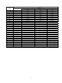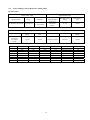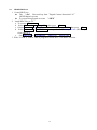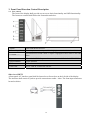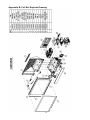
1
TOSHIBA
FILE NO. 053-200110
SUPPLEMENT
SERVICE MANUAL
COLOR TELEVISION
42HM66
13A21
PARTS AND DIAGRAMS
DOCUMENT
IN JAPAN,
JAPAN, Mar.,
Nov., 2006
DOCUMENT CREATED IN
2002
TABLE OF CONTENT
1.
2.
3.
4.
Precautions and Safety Notices.........................................................................................................3
Specification......................................................................................................................................4
2.1.
General ..............................................................................................................................4
2.2
Instrument Test...................................................................................................................5
2.3.
TV Channel Table. ............................................................................................................9
2.4.
Preset Timing Chart & Reference Timing Table.............................................................12
2.5
DDC Contents .................................................................................................................14
2.6
HDMI-HDCP test............................................................................................................15
Front Panel Function Control Description ......................................................................................16
3.1
User control.....................................................................................................................16
3.2
OSD Functions..............................................................................................................17
Circuit Description..........................................................................................................................29
4.1
Main Board .....................................................................................................................29
4.2
Power Supply Circuit Description ..................................................................................34
4.3
Formatter Board Circuit Description ..............................................................................35
4.4
Function Key Board Circuit Description ........................................................................36
4.5
LED Board Circuit Description ......................................................................................36
4.6
IR Board Circuit Description ..........................................................................................36
4.7
SmoothPictureTM Board Circuit Description ..................................................................36
5.
Trouble Shooting Flow Chart..........................................................................................................37
5.1
No Display on Screen (Screen is black, no power).........................................................37
LED error message. ..............................................................................................................................37
5.2
No Sound (Test signal: 0.5Vrms sine waveform) ...........................................................38
5.3
Protection ......................................................................................................................39
6. Service adjustment ...........................................................................................................................43
6.1
Service adjustment procedure ..........................................................................................43
6.2
Service Adjustment List (in Factory Mode).....................................................................45
Appendix A: ISP......................................................................................................................................46
Appendix B: Full Set Explode Drawing .................................................................................................48
Appendix C: Disassembly.......................................................................................................................49
Appendix D: Recommended Parts List...................................................................................................62
2
1. Precautions and Safety Notices
Prior to using this manual, please ensure that you have carefully followed all the procedures outlined in the user manual
for this product.
•
Read all of these instructions.
•
Save these instructions for later use.
•
Follow all warnings and instructions marked on the product.
•
Do not use this product near water.
•
This display should be installed on a solid horizontal base.
•
When cleaning, use only a neutral detergent cleaner with a soft damp cloth. Do not spray with liquid or aerosol
cleaners.
•
Do not expose this display to direct sunlight or heat. Hot air may cause damage to the cabinet and other parts.
•
Adequate ventilation must be maintained to ensure reliable and continued operation and to protect the display from
overheating. Do not block ventilation slots and openings with objects or install the display in a place where
ventilation may be hindered.
•
Do not install this display near a motor or transformer where strong magnetism is generated. Images on the display
will become distorted and the color irregular.
•
Do not allow metal pieces or objects of any kind fall into the display from ventilation holes.
Slots and openings in the cabinet and the back or bottom are provided for ventilation, to ensure reliable operation of the
product and to protect it from overheating, those openings must not be blocked or covered. The openings should never
be blocked by placing the product on a bed, sofa rug, or other similar surface. This product should never be placed near
or over a radiator or heat register. This product should not be placed in a built-in installation unless proper ventilation is
provided.
3
2. Specification
2.1.
General
2.1.1
General Description (Quick Reference)
42 inch Real-Projection TV Specification
DVR-4240 TA CA
Model Name
Type Color
Panel
42" (42" viewable diagonal area), Rear projection, 1280 x 720 (By
SmoothPictureTM Technology)
Video/Audio
Input Signal
HDMI * 1 (HDCP support) / RCA (L/R) * 1
TV system antenna *1 / NTSC /ATSC / CLEAR QAM
Component Video * 2 / RCA (L/R) Stereo * 2
Composite * 1 / S–Video * 1 / RCA (L/R) stereo * 1
Composite * 1 / RCA (L/R) Stereo * 1
Output1: 1 R/L audio output
Output Signal
Output2: SPDIF Coaxial
HDTV Compatibility
480i, 480P, 720P, 1080i
Speaker Output
10w (x2 Channels)
Voltage
Power
Temperature (Note A) Operating
Storage
(Relative). Operating
Humidity
100~132VAC (USA)
+10 to + 40° C (Hum.<90%)
-20 to +60 oC (Hum.< 35 %)
20 to 90% non-condensing.(Ta< 35%)
(Note A)
Storage
10 to 90% non-condensing. (Note A)
Wet-bulb temperature should be 39 oC Max. (Ta> 40oC)
Note A: The temperature and relative humidity range is
shown in right side
Operating
0 to 3,000 m
Storage
0 to 12,000m
Dimensions
Physical
996mm (W) x 721.5mm (H) x 319.5mm (D)
Weight
Net / Gross
25.5kg / 31.5kg
Altitude
UL, CUL, FCC
Regulations
Power saving
Modes
Active Off
Power off < 1 W at 110VAC
Preset Timing Mode (Pre-adjusted to reduce blanking: 1280 x 720 at 60Hz)
Warning: Do not set the graphics card in your computer to exceed these refresh rates; doing so may result in permanent
damage to the RPTV.
Note: Product Specifications are subject to change without notice.
4
2.2
Instrument Test
2.2.1. Luminance test.
Select HDMI 1280x720 @ 60Hz input: (Contrast, Brightness =default)
2.2.1.1 White balance.
a. WARM:
x = 0.313 ± 0.01.
y = 0.329 ± 0.01.
b. MEDIUM:
x = 0.289 ± 0.01.
y = 0.289 ± 0.01.
c. COOL:
x = 0.270 ± 0.01.
y = 0.270 ± 0.01.
2.2.1.2 Adjust contrast & brightness to 100%, the Y > 400cd/m2.
2.2.1.3 In HDMI mode with contrast and brightness =default) and the 32 grays scale have 2 bright scale saturation is
acceptable.
When Contrast 100% and with 32grays need > 4 level saturation.
In video mode (Color Stream HD, Composite, S-Video, TV, DVI-HDTV mode):
When Contrast 100% and with 32grays need > 4 level saturation.
2.2.1.4 White uniformity: (9 point max.- 9 point min.) Meter normal to Screen.
a. Specification: Δx and Δy should be less than ΔWx: 0.016, ΔWy:0.020
1
2.2.2. Picture performance test.
2.2.2.1 Video performance test:
Apply pattern: Color bars (COL_SMPTE), Crosshatch, Multi burst, Black & White, Gray scale.
Color bars (COL_SMPTE).
Multi burst.
FIG.18
Black & White.
5
2.2.2.1.1 Connected video signal source to AV port:
2.2.2.1.1.1 In color bar (COL_SMPTE) pattern,
a. The color from left side to right side should be White, Yellow, Sky Blue, Green, Magenta, Red and Blue.
b. The low light 10.7 IRE in the right bottom side should be separate clear.
c. Used the Blue color filter to check the Hue and Saturation were in the optimize point.
(Saturation: The Blue and White color should be the same when see through by Blue color filter.)
(Hue: The Magenta and Sky Blue color should be the same when see through by Blue color filter.)
2.2.2.1.1.2 In Crosshatch pattern, it should be no visible noise.
2.2.2.1.1.3 In Multi burst pattern:
a. In low bandwidth pattern, there are no any dots on the edge transitions.
b. In high bandwidth pattern, can not loss any resolution and the scaling should be correct.
c. There is no visible noise in this pattern.
2.2.2.1.1.4 In Black & White, there is no any trouble at edge transition.
2.2.2.1.1.5 In Gray Scale pattern, the gray scale should not be saturation.
2.2.2.1.2. Connected video signal source to S-Video port:
2.2.2.1.2.1 In color bar (COL_SMPTE) pattern:
a. The color from left side to right side should be White, Yellow, Sky Blue, Green, Magenta, Red and Blue.
b. There were no any dot crawl between color bar, but still had light smearing.
c. The low light 10.7 IRE in the right bottom side should be separate clear.
d. Used the Blue color filter to check the Hue and Saturation were in the optimize point.
(Saturation: the Blue and White color should be the same when see through by Blue color filter.)
(Hue: the Magenta and Sky Blue color should be the same when see through by Blue color filter.)
2.2.2.1.2.2. In Crosshatch pattern, it should be no visible noise.
2.2.2.1.2.3 In Multi burst pattern:
a. In low bandwidth pattern, there are no any dots on the edge transitions.
b. In high bandwidth pattern, can not loss any resolution and the scaling should be correct.
c. There is no visible noise in this pattern.
2.2.2.1.2.4 In Black & White, there is no any trouble at edge transition.
2.2.2.1.2.5 In Gray Scale pattern, the gray scale should not be saturation.
2.2.2.1.3 Connected video signal source to Color Stream HD (YPbPr) port:
2.2.2.1.3.1 In color bar (COL_SMPTE) pattern:
a. The color from left side to right side should be White, Yellow, Sky Blue, Green, Magenta, Red and Blue.
b. There were no any dot crawl and smearing between color bar.
c. The low light in the right bottom side should be separate clear.
2.2.2.1.3.2. In Crosshatch pattern, it should be no visible noise.
2.2.2.1.3.3 In Multi burst pattern:
a. In low bandwidth pattern, there are no any dots on the edge transitions.
b. In high bandwidth pattern, can not loss any resolution and the scaling should be correct.
c. There is no visible noise in this pattern.
2.2.2.1.3.4 In Black & White, there is no any trouble at edge transition.
2.2.2.1.3.5 In Gray Scale pattern, the gray scale should not be saturation.
2.2.2.1.4 Connected video signal source to TV (Composite Video) port:
2.2.2.1.4.1 Test Channel:
a. Channel 1 ~ Channel 6 (55.25 MHz ~ 77.25 MHz), choice one channel to test.
b. Channel 95 ~ Channel 99 (91.25 MHz ~ 115.25 MHz), choice one channel to test.
c. Channel 14 ~ Channel 22 (121.25 MHz ~ 169.25 MHz), choice one channel to test.
d. Channel 7 ~ Channel 94 (175.25 MHz ~ 643.25 MHz), choice one channel to test.
e. Channel 100 ~ Channel 125 (649.25 MHz ~ 799.25 MHz), choice one channel to test.
2.2.2.1.4.2 In color bar (COL_SMPTE) pattern,
a. The color from left side to right side should be White, Yellow, Sky Blue, Green, Magenta, Red and Blue.
b. The low light 10.7 IRE in the right bottom side should be separate clear.
c. Used the Blue color filter to check the Hue and Saturation were in the optimize point.
(Saturation: the Blue and White color should be the same when see through by Blue color filter.)
(Hue: the Magenta and Sky Blue color should be the same when see through by Blue color filter.)
6
2.2.2.1.4.3 In Crosshatch pattern, it should be no visible noise.
2.2.2.1.4.4 In Multi burst pattern:
a. In low bandwidth pattern, there are have same dots on the edge transitions which are acceptable.
b. In high bandwidth pattern, there are cannot loss any resolution and the scaling should be correct.
2.2.2.1.4.5 In Black & White, there is no any trouble at edge transition.
2.2.2.1.4.6 In Gray Scale pattern, the gray scale should not be saturation.
2.2.2.1.4.7 Apply cable TV or RF pattern generator signal and the RF sensitivity set to 45 ~85dBµV, the image
should be displayed.
If under 60dBµV, the image had snow noise was acceptable but can not loss any color.
2.2.2.1.4.8 TV Channel Auto Scan
a . The NTSC system TV channel and frequency table as 2.4 TV Channel Table
2.2.2.1.4.9 V-Chip & Close caption function test:
a. Close caption:
a.1 Select the “Close Caption” (In main picture OSD) to CC1, CC2, CC3, CC4, TT1, TT2, TT3, TT4.
a.2 Setting the FLUKE 54200 or VG848 / 858 function to CC number 1, CC number 2, CC number 3, CC
number 4, CC number 5, CC number 6, CC number 7, CC number 8, the function should be normally. Or
a.3 Used signal center channel with CC function. TV select to same CC number with signal center.
b. Parental Control
b.1 Select the “Parental Control” in OSD and key in password “2097” enter to the TV rating and setting all
the rating to “LOCKED”.
b.2 Setting the FLUKE 54200 or VG848 / 858 or used signal center channel with CC Sequence, the image
will be locked and show key in password and rating message. After key in password and the password is
correct, the image will display again.
2.2.2.1.5 Distortion test:
a. Apply green cross hatch pattern.
b. Distortion spec:
b-1. Tilt spec: (Parallelogarm)
|A-K| <=5mm
|E-G| <=5mm.
|B-D| <=5mm
|J-H| <=5mm.
b-2. Keystone spec:
|(A+E) - (K+G)| <= 6mm.
|(B+J) - (D+H)| <= 7mm.
b-3. Distortion spec: (Pincushion and Barrel)
|(A-L) + (K-L)| /2 less than 5mm.
|(E-F) + (G-F)| /2 less than 5mm.
|(B-C) + (D-C) |/2 less than 4mm.
|(J-I) + (H-I)| /2 less than 4mm.
b-4. Position spec:
H position: |C-I| <= 8mm.
V position: |L-F| <= 10mm.
FIG.7
7
2.2.2.1.5 Focus:
Used TV tested pattern inspect Focus and Flare. In factory menu to enter SYSTEM then select to DLP TEST PATTERN
press ENTER button by remote control. The Green Diagonal line will display on screen. The EXIT button can return to
factory menu.
Green Diagonal line
Fig26.
Fig27.
Optical engine:
Unit (pixel)
Focus
Flare
Center
1.7
2
Corner
2.1
2.5
Unit (pixel)
Focus
Flare
Center
1.9
2.2
Corner
2.4
3.0
Full set:
3. Power supply tests.
3.1 Power consumption test table:
TV status
Power on (Normal operation)
DC power off (stand by)
LED color
Green
Orange
Picture
Active
NA
Power consumption
<280W
<1W at 110VAC
3.2 Dielectric withstand voltage:
3.2.1 Primary to safety ground:2500VDC for 1.5 sec.
3.2.2 Leakage current ≦ 10mA
4. DDC test.
4.1 DDC / EDID specification compliance requirement.
The data that is communicated shall be stored in the monitor in non-volatile, which is a subset of the VESA EDID
version 3.0 standard.
4.2 The EDID data see DDC contents.
5. Audio test:
5.1 Connected AV1 & AV2 (AV & S-Video) audio input source to AV L/R audio input, the speaker L and R should be
output and the distortion (THD) ≦ 10% at 20Hz to 20KHz, and the audio function of Balance, Bass, Treble should
be working normally.
5.2 Connected Color Stream HD 1 & 2 audio input source to Color Stream HD 1 & 2 L/R audio input, the speaker L and
R should be output and the distortion (THD) ≦ 10% at 20Hz to 20KHz, and the audio function of Balance, Bass,
Treble should be working normally.
5.3 Audio output test: When each audio had input, then audio output RCA jack (L/R), must output 0.5Vrms (1.414Vp-p).
6. HDCP test. (Only for HDCP model)
6.1 See the HDCP test.
8
2.3.
TV Channel Table.
Channel
Number
AIR
1
2
3
4
5
6
7
8
9
10
11
12
13
14
15
16
17
18
19
20
21
22
23
24
25
26
27
28
29
30
31
32
33
34
35
36
37
38
39
40
41
42
43
44
45
--55.25
61.25
67.25
77.25
83.25
175.25
181.25
187.25
193.25
199.25
205.25
211.25
471.25
477.25
483.25
489.25
495.25
501.25
507.25
513.25
519.25
525.25
531.25
537.25
543.25
549.25
555.25
561.25
567.25
573.25
579.25
585.25
591.25
597.25
603.25
609.25
615.25
621.25
627.25
633.25
639.25
645.25
651.25
657.25
STD
--55.25
61.25
67.25
77.25
83.25
175.25
181.25
187.25
193.25
199.25
205.25
211.25
121.25
127.25
133.25
139.25
145.25
151.25
157.25
163.25
169.25
217.25
223.25
229.25
235.25
241.25
247.25
253.25
259.25
265.25
271.25
277.25
283.25
289.25
295.25
301.25
307.25
313.25
319.25
325.25
331.25
337.25
343.25
349.25
Picture Carrier Frequency (MHz)
CABLE
HRC
72.00
54.00
60.00
66.00
78.00
84.00
174.00
180.00
186.00
192.00
198.00
204.00
210.00
120.00
126.00
132.00
138.00
144.00
150.00
156.00
162.00
168.00
216.00
222.00
228.00
234.00
240.00
246.00
252.00
258.00
264.00
270.00
276.00
282.00
288.00
294.00
300.00
306.00
312.00
318.00
324.00
330.00
336.00
342.00
348.00
9
IRC
73.25
55.25
61.25
67.25
79.25
85.25
175.25
181.25
187.25
193.25
199.25
205.25
211.25
121.25
127.25
133.25
139.25
145.25
151.25
157.25
163.25
169.25
217.25
223.25
229.25
235.25
241.25
247.25
253.25
259.25
265.25
271.25
277.25
283.25
289.25
295.25
301.25
307.25
313.25
319.25
325.25
331.25
337.25
343.25
349.25
Channel
Number
46
47
48
49
50
51
52
53
54
55
56
57
58
59
60
61
62
63
64
65
66
67
68
69
70
71
72
73
74
75
76
77
78
79
80
81
82
83
84
85
86
87
88
89
AIR
663.25
669.25
675.25
681.25
687.25
693.25
699.25
705.25
711.25
717.25
723.25
729.25
735.25
741.25
747.25
753.25
759.25
765.25
771.25
777.25
783.25
789.25
795.25
801.25
STD
355.25
361.25
367.25
373.25
379.25
385.25
391.25
397.25
403.25
409.25
415.25
421.25
427.25
433.25
439.25
445.25
451.25
457.25
463.25
469.25
475.25
481.25
487.25
493.25
499.25
505.25
511.25
517.25
523.25
529.25
535.25
541.25
547.25
553.25
559.25
565.25
571.25
577.25
583.25
589.25
595.25
601.25
607.25
613.25
Picture Carrier Frequency (MHz)
CABLE
HRC
354.00
360.00
366.00
372.00
378.00
384.00
390.00
396.00
402.00
408.00
414.00
420.00
426.00
432.00
438.00
444.00
450.00
456.00
462.00
468.00
474.00
480.00
486.00
492.00
498.00
504.00
510.00
516.00
522.00
528.00
534.00
540.00
546.00
552.00
558.00
564.00
570.00
576.00
582.00
588.00
594.00
600.00
606.00
612.00
10
IRC
355.25
361.25
367.25
373.25
379.25
385.25
391.25
397.25
403.25
409.25
415.25
421.25
427.25
433.25
439.25
445.25
451.25
457.25
463.25
469.25
475.25
481.25
487.25
493.25
499.25
505.25
511.25
517.25
523.25
529.25
535.25
541.25
547.25
553.25
559.25
565.25
571.25
577.25
583.25
589.25
595.25
601.25
607.25
613.25
Channel
Number
90
91
92
93
94
95
96
97
98
99
100
101
102
103
104
105
106
107
108
109
110
111
112
113
114
115
116
117
118
119
120
121
122
123
124
125
AIR
STD
619.25
625.25
631.25
637.25
643.25
91.25
97.25
103.25
109.25
115.25
649.25
655.25
661.25
667.25
673.25
679.25
685.25
691.25
697.25
703.25
709.25
715.25
721.25
727.25
733.25
739.25
745.25
751.25
757.25
763.25
769.25
775.25
781.25
787.25
793.25
799.25
Picture Carrier Frequency (MHz)
CABLE
HRC
618.00
624.00
630.00
636.00
642.00
90.00
96.00
102.00
108.00
114.00
648.00
654.00
660.00
666.00
672.00
678.00
684.00
690.00
696.00
702.00
708.00
714.00
720.00
726.00
732.00
738.00
744.00
750.00
756.00
762.00
768.00
774.00
780.00
786.00
792.00
798.00
11
IRC
619.25
625.25
631.25
637.25
643.25
91.25
97.25
103.25
109.25
115.25
649.25
655.25
661.25
667.25
673.25
679.25
685.25
691.25
697.25
703.25
709.25
715.25
721.25
727.25
733.25
739.25
745.25
751.25
757.25
763.25
769.25
775.25
781.25
787.25
793.25
799.25
2.4.
Preset Timing Chart & Reference Timing Table
RF Video Input
Analog Video Input
Signal Formal
Demodulated Video
Channels
Signal Formate
Horizontal Freq.
(KHz)
Vertical Freq.
(Hz)
2~69 (Antenna)
1~125 (Cable)
4:3 & 16:9
Composite
NTSC
15.734
59.940
Freq.
RF Modulate System M 55.25~801.25
Base band Video Input
Analog Video Input
Decoded Digital Video
Signal Formal
Horizontal Freq.
(KHz)
Vertical Freq.
(Hz)
Active Resolution
Total
Pixel clock
(MHz)
4:3 & 16:9
Composite
YC/YcbCr
NTSC
15.734
59.940
720*240 / 59.94 I
858*525
13.500
Color Stream HD Video Input
HDTV
EDTV
SDTV
Format
1080i
720p
480p
480p
480p
480i
480i
480i
V scan line
1080
720
480
480
480
480
480
480
H pixel
1920
1280
704
704
640
704
704
640
12
Aspect ratio
16:9
16:9
16:9
4:3
4:3
16:9
4:3
4:3
Scan format
Interlaced scan
Progressive scan
Progressive scan
Progressive scan
Progressive scan
Interlaced scan
Interlaced scan
Interlaced scan
Frame (fps)
30
60
60
60
60
30
30
30
HDMI timing:
Mode No.
Mode Name
Horizontal Freq.
(KHz)
1
VESA
640 x
480
2
MAC
640 x
480
3
VESA
640 x
480
4
VESA
640 x
480
5
TEXT
720 x
400
6
VESA
800 x
600
7
VESA
800 x
600
8
VESA
800 x
600
9
VESA
800 x
600
10
MAC
832 x
624
31.469
35.000
37.861
37.500
31.469
35.156
37.879
48.077
46.875
49.727
30.240
31.500
31.500
28.322
36.000
40.000
50.000
49.500
57.285
-
864
64
96
640
64
66.667
-
525
3
39
480
3
-
832
40
128
640
24
72.809
-
520
3
28
480
9
-
840
64
120
640
16
75.000
-
500
3
16
480
1
-
900
108
54
720
18
70.087
+
449
2
35
400
12
+
1024
72
128
800
24
56.250
+
625
2
22
600
1
+
1056
128
88
800
40
60.317
+
628
4
23
600
1
+
1040
120
64
800
56
72.188
+
666
6
23
600
37
+
1056
80
160
800
16
75.000
+
625
3
21
600
1
-
1152
64
224
832
32
74.553
-
667
3
37
624
3
11
VESA
848 x
480
29.830
31.50
-
1056
12
VESA
1024 x
768
48.363
65.000
-
1344
13
VESA
1024 x
768
56.476
75.000
-
1328
14
VESA
1024 x
768
60.023
78.750
+
1312
15
VESA
1280 x
720
44.772
74.5
-
1664
16
17
18
19
20
80
136
136
96
104
8484
24
59.659
+
500
5
12
480
3
160
1024
24
60.004
-
806
6
29
768
3
144
1024
24
70.069
-
806
6
29
768
3
176
1024
16
75.029
+
800
3
28
768
1
Video clock Freq.
25.175
(MHz)
-
Sync. Polarity
H. total
(Dots)
800
H. sync. (Dots)
96
H. back porch (Dots)
48
H. active
(Dots)
640
H. front porch (Dots)
16
Vertical Freq. (Hz)
59.940
-
Sync. Polarity
V. total
(Lines)
525
V. sync.
(Lines)
2
V. back porch (Lines)
33
V. active
(Lines)
480
V. front porch (Lines)
10
Mode No.
Mode Name
Horizontal Freq.(KHz)
Video clock Freq.
Sync. Polarity
H. total
(Dots)
H. sync.
(Dots)
H. back porch (Dots)
H. active
(Dots)
H. front porch (Dots)
Vertical Freq. (Hz)
Sync. Polarity
V. total
(Lines)
V. sync.
(Lines)
V. back porch (Lines)
V. active
(Lines)
V. front porch (Lines)
13
480p
720p
1080i
(Video) (Video) (Video)
31.47
27.00
-
858
44.95
74.175
+
1650
33.72
74.175
+
2200
128
62
40
44
192
1280
64
59.855
+
748
5
20
720
3
60
720
220
1280
148
1920
59.94
-
525
6
30
480
59.94
+
750
5
20
720
29.97
+
562
5
15
540
2.5
DDC Contents
a. HDMI 256 bytes EDID code. (For DVR4240 TA CA (Toshiba))
EDID block0:
0
0
00
10
40
20
80
30
A9
30
01
50
01
60
1C
70
00
80
68
90
00
100
00
110
00
120
20
1
FF
42
5D
25
01
01
20
1C
69
00
0A
FC
20
2
FF
01
34
0E
01
01
40
00
62
00
20
00
20
3
FF
01
78
45
01
01
80
00
61
FD
20
34
20
4
FF
01
2A
4A
01
1A
35
00
0A
00
20
32
20
5
FF
01
30
20
01
1D
00
FE
20
32
20
48
20
6
FF
03
31
00
01
00
A2
00
20
4B
20
4D
01
7
00
10
A2
00
01
80
08
54
20
1E
20
36
62
8
52
01
55
01
01
51
32
6F
20
50
00
36
Rev:01
9
62
03
4C
01
01
D0
00
73
20
0E
00
0A
1
03
07
03
D0
00
20
9E
3E
0A
00
00
00
00
2
1A
23
0C
1E
00
58
8C
96
D0
A2
00
00
00
3
71
09
00
20
1E
2C
0A
00
8A
08
00
00
00
4
47
07
10
6E
01
25
D0
A2
20
32
00
00
00
5
84
07
00
28
1D
00
8A
08
E0
00
00
00
00
6
05
83
01
55
80
A2
20
32
2D
00
00
00
00
7
02
01
1D
00
18
08
E0
00
10
18
00
00
B9
8
03
00
00
A2
71
32
2D
00
10
00
00
00
9
01
00
72
08
1C
00
10
18
3E
00
00
00
EDID block1:
0
10
20
30
40
50
60
70
80
96
100
110
120
0
02
06
65
51
32
16
00
10
8C
96
00
00
00
14
2.6
HDMI-HDCP test
1. Create HDCP key:
The “*.dat" files need buy from“Digital Content Protection LLC"
(WWW.digital-cp.com)
To execute this program to create “*.HEX".
2. Install HDCP key to TV.
a. To execute GProbe 4.exe
b. Select Commends to DebugON
then press
Enter
c. Select Commands to SetBuffer address= 0X600 length=300 then press
Enter
d. Select Commands to NVRAMWrite then input the file of factoryxxx.hex (HDCP keys)
from address=0
e.
Set Commands to NVRAMRead
address=0
length=300
3. With “VG848 or VG858” HDCP program to check the TV set HDCP function.
15
3. Front Panel Function Control Description
3.1 User control
The front of the display shall provide user access to basic functionality and OSD functionality.
The front user controls shall follow the format shown below:
1. Menu
Turn OSD Menu ON/OFF
2. Channel up / down Channel up/down when Input is TV or highlight a control while in the OSD Menu.
3. Volume + / -
Increase/Decrease sound volume or adjust a highlighted control while in the OSD
Menu.
4. Input
Select Active Video Input or choose a selection while in the OSD MENU.
5. Power Button
Power ON/OFF
6.IR Lens
IR Receiver
7.LED Lens
“Power “LED” & “LAMP LED” indicator.
Side view of RPTV
A front panel A/V interface panel shall be located on a tilt out door on the left side of the display.
The interface shall consist of jacks to provide connection to audio / video. The front input connectors
located as below:
16
Rear interface:
The main interface for the display shall be on the back of the unit. The interface shall consist of jacks
for tuner input, audio, video interfaces and HDMI interfaces. The rear connectors shall be located as
shown below:
FIG.13
3.2 OSD Functions
All the OSD function settings are controlled either by the remote control or using the control keys on
the right side of RPTV.
To display the OSD main menu, press the Menu button on the right side of the RPTV or on the remote
control. Use ▲ ▼ arrow keys to highlight the desired OSD sub-menu.
17
Main Menu
To select a sub-menu, press
on the right side of the RPTV or the
18
key on the remote control.
IMAGE SETTING:
Function Name
Function
Scheme
USER → VIVID
→ DIMMER
Brightness
Brightness adjustment
Contrast
Contrast adjustment
Color
Saturation adjustment
Tint
Hue adjustment
Sharpness
Sharpness adjustment
Color Temp
Color temperature adjustment (Cool, Medium, Warm)
Reset
Reset video settings
19
→ GAME → SPORT
DISPLAY SETTING:
Function Name
Function
Main Source
Select main screen sources
TV DTV AV1 AV2 S Video Color Stream HD-1
HD-2 HDMI
Color Stream
PIP Source
Select sub screen sources
See PIP/PBP/POP specification in Table 1 (PIP function list)
Aspect Ratio
Set display to “STANDARD” / “FILL” / “ZOOM”
PIP Mode
OFF PIP PBP POP
Swap
Swap main screen and sub-screen source
PIP Size
Sub-screen display size adjustment
(Small Medium Large)
PIP Position
Sub-screen display horizontal/vertical position adjustment
Audio From
Select main screen or sub-screen audio sources
Table 1: PIP function list
SUB
Main
TV
AV1
AV2
S-Video
Color Stream HD-1
Color Stream HD-2
HDMI
TV
AV1
AV2
S-Video
X
X
X
X
X
X
O
X
X
X
X
X
X
O
X
X
X
X
X
X
O
X
X
X
X
X
X
O
20
Color Stream
HD-1
X
X
X
X
X
X
O
Color Stream
HD-2
X
X
X
X
X
X
O
HDMI
O
O
O
O
O
O
X
AUDIO SETTINGS:
Function Name
Function
Bass
Bass adjustment
Treble
Treble adjustment
Balance
Balance adjustment
MTS
MTS Selection
NOTE: This function depends on the type of broadcast being received.
Mute
Select Audio OFF or ON
Speaker
Select internal or external speaker
Reset
Reset audio settings
21
TV/DTV SETTINGS:
Function Name
Function
TV System
Select TV source type (ANTENNA
Cable IRC)
Auto Scan
Automatically detect available TV channels
Channel EDIT
Add/Delete the selected TV channel
Local Time
Day Light
22
Cable STD
Cable HRC
PARENTAL CONTROLS:
Function Name
Function
Password
Turn parental control OFF or ON
TV PG Rating
See next page
MPAA Rating
See next page
RRT
Open V-chip function
Password EDIT
Change Password (see next page)
TV PG Rating
TV Y: All children
TV Y7: For older children
TV G: General audience
TV PG: Parental guidance suggested
TV 14: Parents strongly cautioned
TV MA: Mature audience only
MPAA Rating
NONE: Not available
G: General audience
PG: Parental guidance suggested
PG-13: Parents strongly cautioned
R: Restricted
NC 17: No one 17 and under admitted
X: Adult audience only
Password Edit
Change Password
23
GENERAL SETTINGS:
Function Name
Function
Transparency
Set OSD transparency level
Menu Position
OSD horizontal/vertical position adjustment
System Info
Display Input source, type and signal
Closed Caption
Turn the Close Caption OFF or CC1, CC2, CC3, CC4, TEXT1,
TEXT2, TEXT3, TEXT4
Language
OSD language selection.
Sleep Timer
Set sleep timer to turn off the power automatically.
Menu Timeout
Set the time to turn off the OSD automatically.
Quick Restart
Low Power Shutdown (LPS) mode selection
Factory Reset
Restore factory default settings
24
Factory Menu
Function Name
Function
MODEL:
TV system model name in factory used.
VER:
TV system software version.
ATSC VER:
ATSC software version.
SYSTEM
Initial TV system/ DTV software update/ Temperature information
IMAGE ADJUST
TV system image/ color/ white balance adjustment.
DLP
DLP function control.
25
Factory Menu- System
Function Name
Function
ALL MODE RECALL
TV system reset to factory shipment setting.
INIT EEPROM
Clear EEPROM. All adjustment will be clear.
RESET ADC VALUE
White balance value reset.
DTV UPDATA
ATSC software update.
DMD TEMP
Around of DMD temperature information.
AMBER TEMP
Ambient temperature information.
DLP TEST PATTERN
DLP test pattern for factory used.
26
Factory Menu- Image adjust
Function Name
Function
SYSTEM
Not available.
De-interlace
Not available.
FILM MODE
Not available.
VDSP
Image quality adjustment.
ADC
White balance alignment.
Debug
Not available.
27
Factory Menu- DLP
Function Name
Function
EAST WEST
Image horizontal invert.
NORTH SOUTH
Image vertical invert.
DLP POSITION
Image position adjustment.
OSD EDGE
Not available.
CONTRAST
DLP contrast adjustment for cool color temperature.
BRIGHTNESS
DLP brightness adjustment.
LAMP
Lamp timer information.
TLIEF AUTO
Not available.
INDEX DELAY
Color wheel index delay adjustment.
GAMMA
Gamma curve selection.
SMOOTH PIC.
SmoothPictureTM on/off control.
SATURATION
Dynamic color function to adjust saturation.
SHARP PICTURE
Dynamic color function to adjust sharp picture.
LAMP SYNC DELAY
Lamp sync delay adjustment.
DYNAMIC CONTRAST Dynamic color function to adjust dark level.
CCA
Not available.
28
4. Circuit Description
4.1 Main Board
4.1.1 Power Supply (DC/DC Converter)
1. 16V, 12V, 5VC, 5VSB id from Power Board.
2. 3V3ATZ from regulator IC203 (5VSB->3.3V)
3. 2V5DDR from regulator IC206 (5VSB->2.5V)
4. 1V8CTZ from regulator IC205 (5VSB->1.8V)
5. 5VT from regulator IC207 (12V->5V)
6. 32VT from DC-DC IC218 (12V->32V)
7. VDD_Core1V5 from DC-DC IC201 (12V->1.5V)
8. 5VA from 5VC
9. 3V3A/ 3V3HDMI from regulator IC202 (5VA->3.3V)
10. 1V8HDMI from regulator IC216 (5VA->1.8V)
11. 2V5VADC/2V5ATSC from regulator IC209 (5VA->2.5V)
12. 1V8ATSC from regulator IC214 (5VA->1.8V)
13. 3V3VDC/3V3ATSC from regulator IC211 (5VA->3.3V)
14. 1V2VDC from regulator IC215 (5VA->1.2V)
4.1.2 Image Processor
The Genesis Microchip FLI8532 (IC404) is a fully integrated single chip solution for LCD TV. It includes an integrated
3-D Digital Video Decoder with Faroudja DCDi Cinema video format conversion, video enhancement, and noise reduction.
The level of video quality that could previously only be seen on an exclusive Faroudja Home Theater System is now
available in a single chip solution.
The auto-detection and Faroudja DCDi Cinema technology allow the FLI8532 to detect, process, and enhance any video or
PC graphic format worldwide without the need for additional hardware.
The integrated VBI dataslicer and decoder allow for significant cost reduction by removing the need for expensive, external
VBI dataslicers and decoders. The FLI8532 supports many worldwide VBI standards for applications of Teletext, Closed
Captioning, V-Chip, and other VBI technologies.
An embedded micro-controller and a versatile OSD in a single device will facilitate rapid development of a reliable and
attractive product.
29
30
4.1.3 Digital Video Format Converter
The FLI8532 (IC404) is a highly integrated digital video format converter for LCD-TV application using
patented de-interlacing and post processing algorithms from Faroudja Laboratories, coupled with highly
flexible scaling, a wide variety of aspect ratio conversions, and other special video enhancing features to
produce the highest quality image.
Inputs
‧ Input all industry standard and non-standard video resolutions, including 480i (NTSC), 480p, 720p,
1080i.
‧ Digital input, 8-bit Y/Cr/Cb (ITU-R BT656), 8-bit Y/Pr/Pb, 16-bit Y Cr/Cb (ITU-R BT601), 24-bit
RGB, YCrCb, YprPb
Outputs
‧ Output resolutions include 480p, 720p,1080i, 1080p.
‧ Interlaced or Progressive output
‧ In the FLI8532, digital output of 24-bit RGB, YCrCb, YPrPb (4:4:4), or 16/20-bit Y Cr/Cb(4:2:2) are
available
‧ Output pixel rate up to 135 MHz maximum
Formats
‧ Input color manipulation matrix supports all color spaces: RGB, YPrPb, 4:4:4 YCrCb, 4:2:2 YCr/Cb,
ITU-R BT656, ITU-R BT601
‧ Output supports digital RGB, YPrPb, 4:4:4 YCrCb and 4:2:2 YCr/Cb
Frame Rate Conversion
‧ Tearless Frame Rate Conversion 50/60/72/75/100/120 Hz
Front End Processing
‧ Motion Adaptive Noise Reduction – Improves picture quality for off-air material.
‧ Cross Color Suppressor (CCS) - Removes cross color artifacts in composite video signals due to
poor Y/C separation in standard 2-D video decoders, eliminating the need for expensive 3-D video
decoders.
31
4.1.4 Video Decoder
The FLI8532 chip has a sophisticated Analog Front End with 16 reconfigurable inputs
through an analog multiplexer to anti-alias filters before the Analog to Digital Converters
(ADCs). These integrated features eliminate the need for any devices between the input
connector and the pin of the FLI8532.
The figure above depicts the data-path for the AFE and Decoder blocks with connections to
the input multiplexer that selects whether the data follows the Main Video Channel or PIP video
channel.
The analog front end of FLI8532 provides the capability to capture 16 analog video inputs
which can be a combination of Composite (CVBS), S-Video (SY, SC), YPrPb (Y, Pr, Pb) or
RGB (R, G, B).
The FLI8532 front end provides filtering capability depending on the type of input video
signal in use. The use of these filters eliminates the need to have any external filter components.
The filters included are both in the analog as well as digital domain. The digital filter eases the
design requirement of the analog anti-aliasing filter.
The analog filter is implemented with the following 3dB cutoff definition.
10 MHz – for SDTV
20 MHz – for 480p/576p
40 MHz – for 720p/1080i
180 MHz – for Graphics
The digital filters are implemented as Quarter Band (QB), for SDTV and 480p/576p and as Half
Band (HB), for 720p/1080i modes.
32
4.1.5 Audio Processor
The MSP3445 is single-chip multi-standard sound processor of NTSC analog TV standard. The full TV sound
processing, starting with analog sound IF signal-in, down to processed analog AF-out, is performed in a single
chip.
This TV sound processing IC include version for processing the multi-channel television sound (MTS) signal
conforming to the standard recommended by the Broadcast Television System Committee (BTSC). Current IC
have to perform adjustment procedures in order to achieve good stereo separation for BTSC. The MSP3445
has optimum stereo performance without any adjustment.
The MSP3445 has built-in automatic function: The IC is able to detect the actual sound standard automatically
(Automatic Standard Detection). Furthermore, pilot levels and identification signals can be evaluated internally
with subsequent switching between mono/stereo/bilingual; no I2C interaction is necessary (Automatic Sound
Selection). The IC also include the Bass and Treble function.
33
4.2 Power Supply Circuit Description
The power supply provides DC electrical power to all the electrical components in the rear projection television.
DVR-4240 also contains Ballast that provides high voltage 380V necessary to strike the lamp when the rear projection
television is powered up. The attached fan draws cooling air through the power supply, as well as through the rest of
the rear projection television.
4.2.1 Location diagram of power board
The power supply consists of the EMI filter, PFC, Standby power, and Main power. The system required voltage is
converted from the Standby and Main power, and the high voltage DC 380V from PFC is applied to the lamp and Main
power.
Line voltage can directly input from 90Vac to 264Vac and boost to 380Vdc for the output, there are common choke
FL1001 and FL1002, and CX1001, CX1002 capacitors to form an EMI filter that can reduce noise and interference.
PFC is main for shaping the AC input line current waveform to correspond to that of the AC input line voltage, and
boost input rectified voltage to 380Vdc for prerequisite.
The output voltage 5Vsb and 5VC are converted from Standby power, when the system is going to the standby mode,
5Vsb is the only output voltage. After the “Power_ON” (CN2002 Pin1) is high, then other voltage outputs are starting
up, otherwise there is only 5Vsb. The 5VC output via Q2006 and under control by 16V depend on Main Power start up,
the other outputs voltage +12V, +16V are converted from Main power. They are the main electrical power for whole
electrical system.
Short circuit protection
All voltage outputs shall have short circuit protection. Only 5Vsb output shall be auto recovery after the short
condition removed.
Over voltage protection
All voltage outputs shall have over voltage protection, 6.24V for 5.25V on 5Vsb outputs; 14.9V for 12V on 12V
outputs; 16V will go follow 12V protection; 415V for 380V output.
Under voltage protection
All voltage outputs shall have under voltage protection, besides +/-20V and 380V outputs (4.12V for 5.1V on 5Vsb
outputs, 9.7V for 12V on 12V outputs.)
34
4.3 Formatter Board Circuit Description
The HD5 SmoothPicture™ Single DDP1011 component set provides a highly integrated, high performance DLP solution,
which enables manufacturers to create 16:9 picture sizes, with high brightness rear projectors. When combined with
external video processing circuitry, the component set provides all the necessary electronics to process video/graphics input
signals, format input data for display on a DLPTM device, and control some of the auxiliary functions of the projector system.
The majority of the circuitry in the HD5 SmoothPicture™ Single DDP1011 reference design is high-speed digital, LVTTL.
High speed digital circuitry includes a single 30-bit input data interface, a SDRAM interface, a Direct Rambus_ memory
channel and a high speed LVDS DMD interface. The HD5 SmoothPicture™ Single DDP1011 reference design also
includes analog circuitry for color wheel motor drive, SmoothPicture™ actuator Control and DMD drive voltage
generation. Proper layout of the high-speed digital and analog circuits is critical to insure a working design.
4.3.1
DDP1011
The DDP1011 (IC9016) is an Application Specific Integrated Circuit (ASIC) intended for use in DLPTM (Digital Light
Processing Technology from Texas Instruments) system applications. The DDP1011 provides selected Video/Graphics
Processing, DMD Data Formatting, Real Time System Control (RSC), and ARM Micro-processor control. The DDP1011 is
designed to work in conjunction with a single 128Mbit or 256Mbit RDRAM™ (Direct RAMBUS(TM) DRAM) and an
associated Direct RAMBUS™ Clock Generator (DRCG) chip. For maximum flexibility, the DDP1011 micro-controller
operates entirely from a single external Flash device. This Flash provides micro-code, configuration parameters and PWM
sequences.
4.3.2
DMD
0.45 inch diagonal spatial light modulator of aluminum micro-mirrors. Display resolution is 1280 columns by 720 rows in a
35
Diagonal Pixel Arrangement. Low Voltage Differential Signaling (LVDS) data interface, Double Data Rate (DDR). Pixel
Architecture is SPD with DarkChip3™.
4.3.3
DAD1000
The DAD1000 (IC9021) DMD Power and Reset Driver provides the high-voltage power supplies and phased reset driver
functions for a family of Digital Micro-mirror Devices (DMDs). The DAD1000 is programmable and controllable to meet
all current and anticipated DMD requirements.
The high-voltage power supply function generates the three required DMD voltage levels: VBIAS, VRESET, and
VOFFSET. These three supplies are programmed and controlled through a TTL and CMOS compatible serial interface. The
DAD1000 also contains a +5 volt supply for internal logic functions and external color wheel control requirements.
The DAD1000 switches outputs between VBIAS, VRESET and VOFFSET voltage levels to form DMD reset waveforms.
VBIAS may be supplied directly to the DMD to bias the border mirrors to the off state. VOFFSET is also supplied directly
to the DMD as DMDVCC2. A fourth DMD power supply, DMDVCC, is supplied directly to the DMD by other circuitry.
4.3.4
CYCLONE
SmoothPicture™ is a technique for storing and displacing consecutive subframes of the image to allow the complete frame
of data to be projected, generating two on-screen pixels with one DMD mirror. SmoothPicture™ also significantly reduces
image pixelization.
4.4 Function Key Board Circuit Description
The Function Key Board provided 7 buttons for control, chouse, select… TV function.
4.5 LED Board Circuit Description
Two LED indicate TV power and Lamp states.
4.6 IR Board Circuit Description
A Infrared Receiver embedding in IR board.
4.7 SmoothPictureTM Board Circuit Description
SmoothPicture™ Actuator Driver.
36
5. Trouble Shooting Flow Chart
5.1 No Display on Screen (Screen is black, no power)
LED error message.
Error1:
2 Green, 1 Orange
LEDG: Blinking
LEDO: Blinking
Hi (OFF)
Error2:
3 Green, 2 Orange
LEDG: Blinking
LEDO: Blinking
Blinking
(0.5sec)
Error3:
5 Green, 2 Orange
LEDG: Blinking
LEDO: Blinking
Hi (OFF)
1. Error 1:
37
Any FAN (1 or 2 or 3) failure or disconnected.
After the fan detects error 5 sec, the LED shows
“ERROR1” message.
Lamp ignition failure, Lamp shut off unexpectedly.
The system will shout down main power go to
standby mode.
DLP hardware error.
5.2
No Sound (Test signal: 0.5Vrms sine waveform)
38
5.3 Protection
5.3.1 Protected flow chart.
5.3.1.1 Firmware protected.
5.3.1.2 Hardware protected (Power board).
39
5.3.1.3 Hardware protected (Ballast board).
5.3.2 Protection functions list.
Item
Function
Description
Condition
Specification
Result
Recovery
Normal
TTL low level
Condition
1
Lamp
MCU (IC404) detect the DMD
working
BD. "LAMPLITZ" (pin P25)
MCU re-ignition the lamp for 5
Remote off/on to
Abnormal
detection
voltage level.
times, if still fail the lamp ignition,
TTL high level
condition
re-start up and
stop the TV power up, show failure
re-ignition
status by LED.
Normal
TTL low level
Condition
MCU turn off the lamp, by set the
Rubycon ballast CN02 PIN4 and
PIN5 to high.
1.(MCU pinP26 (LAMPSYNCEN)
MCU (IC404) detect the pin1
2
Fan rotate
-->CN404 pin28-->DMD BD
voltage of CN5001, CN5002
detection
Abnormal
and CN5003.
CN9002
Remote off/on to
TTL high level
condition
pin28-->Q9004/Q9003(buffer)-->Ba re-start up
llast pin4(Lamp Enable set to high);
2.(MCU pinP24 (LAMPPWR)
-->CN404 pin10-->DMD BD
CN9002 pin10-->Q9005-->Ballast
pin5(ECO-LPS set to high))
40
3
Normal
<=73 degree C
Condition
MCU power off the main power
supply.(MCU
DMD
MCU (IC404) read the DMD
pinT26(POWERON)-->CN201
board
board IC9007 temperature via
thermal
I2C bus.
sensor
pin13-->Power Board CN202
Abnormal
Remote off/on to
>73 degree C
pin1-->Q2005(buffer)-->Q2004/IC2
condition
re-start up
004(photo
coupler)-->Q1006/Q1005(VCC
control for Power ICs
IC1001/IC1002/IC1005))
Normal
<=50 degree C
Key board MCU (IC404) read the Key
4
Condition
thermal
board IC901 temperature via
sensor
I2C bus.
Abnormal
MCU power off the main power
Remote off/on to
supply.
re-start up
>50 degree C
condition
Door close,
Normal
micro switch is
IC2004 connect to micro switch Condition
on
Micro
and supply the VCC to power
switch for
5
Power IC no VCC, Power supply
IC, if micro switch is open the
lamp door
shutdown immediately.(Micro
VCC of power IC is off thus
open
Door open,
Abnormal
the main power supply cans not
detection
SW.-->IC2004(photo
Remote off/on to
coupler)-->Q1006/Q1005(VCC
re-start up
micro switch is
condition
work.
off.
control for Power ICs
IC1001/IC1002/IC1005)
F1001 serial with AC input
Power
line, if AC input current over
Normal
AC input current
supply AC
fuse rating (5A 250V), the fuse Condition <5A
6
line fuse
will open immediately.
AC off-->replace
Abnormal AC input current
Fuse open, no power.
condition
FUSE-->AC
>5A
on-->remote on
41
7
Normal
12V output
Condition <16.42V (typ)
Power IC no VCC, Power supply
D2005(zener diode) connect
shutdown immediately.
between 12V and SCR2001, if
(12V-->D2005 (zener diode)
Power
12V voltage over 16.42V typ.
supply
(16.05~16.79V) the SCR will
/R2018/D2006-->SCR2001-->D201
OVP
AC off/on to re-start
Abnormal 12V output
4/IC2004 (photo coupler)-->Q1006/
condition
Q1005 (VCC control for Power ICs
turn on then cut off the VCC of
up (AC off-->5VSB
>16.42V(typ)
power IC cause power supply
off-->SCR2001 off)
IC1001/IC1002/IC1005); SCR hold
shutdown.
up current:
5VSB-->Q2004-->R2043-->SCR20
01.
Transformer
Normal
secondary
The power IC(IC1001, IC1003,
Condition components are
IC1005) have a input pin for
Power
no failure.
current sense function, the
8
supply
Any transformer Power supply into to protection
current sense function are for
short circuit
secondary
error amplifier feedback loop
protection
and short circuit protection
function.
Thermal
9
Abnormal components are sense voltage at each re-start up
AC off-->remove
condition
short circuit-->AC on
Normal
protection
state. (Power IC detect the current
failure (winding, cycle, and will auto recovery
diode,
immediately after the short circuit
capacitor).
condition remove)
<105 degree C
Condition (typical)
TH1: 100~110 degree C (105
function on
degree C typ)
Abnormal >105 degree
ballast
AC off --> Check fan
Ballast shutdown.
condition
C(typical)
status --> AC on
board
Over
Normal
voltage
Condition
<150V(typ)
VL=150V(typ), range
10
protection
140V~160V; VL=220V(typ)
function on
Abnormal
LPS mode.
ballast
>150V(typ)
Ballast shutdown.
condition
board
Short
Normal
circuit
Condition
>10V
11
protection
VL<10V
function on
Abnormal
ballast
condition
VL<10V
board
42
Ballast shutdown.
6.
6.1
Service adjustment
Service adjustment procedure
6.1.1 Entry Factory Menu
(1) Open the user menu.
(2) Select GENERAL SETTING
(3) Entry GENERAL SETTING then select FACTORY RESET
(4) Type “2”, “0”, “0” and “5” through remote control. The FACTORY MANUAL will appear
43
6.1.2 Index delay adjustment
(1) Before download new software or replace new module should record INDEX DELAY value. (If TV system can
normally display image.)
(2) Download new software or replace new module (Main board or DMD board).
(3) Turn on the TV then entry FACTORY MENU to adjust INDEX DELAY value.
(3-1) Index delay value refer to before record value (step1). or
(3-2) Index delay value can be found from the sticker of light engine. or
(3-3) If you cannot find this sticker, please technician enter the average value" 90" and then check if the
picture is ok or not.
6.1.3 DLP position
(1) Before download new software or replace new module should record DLP position value. (If TV system can
normally display image.)
(2) Download new software or replace new module (Main board or DMD board).
(3) Turn on the TV then entry FACTORY MENU to adjust DLP position.
(4) The TV image should on the screen center and full screen. (Refer to section 2.2.2.1.5 Distortion test)
(5) If technician cannot get the related value before replace new board, then new main board is programmed with
factory average value. Technician just to check image on the screen and full screen.
6.1.4 Color temperature
The color temperature is programmed in software. This section indicated find-turn color temperature to meet
specification. Fine-turn procedure need follow step1. Adjust DLP contrast. Then adjust color2 next adjust color1 in
color temperature.
(1) Before download new software or replace new Main board module should record DLP – Contrast value &
Color Temperature value. (If TV system can normally display image.)
(2) Download new software or replace new Main board module.
(3) Turn on the TV then entry FACTORY MENU to adjust DLP – Contrast & Color Temperature.
(4) If technician cannot get the related value before replace new board, then new main board is programmed with
factory average value.
44
Note: Color Temperature has three set different value about color1, color2 and color3.
Color1= Warm; Color2= Medium; Color3= Cool
6.1.5 White balance adjustment
The white balance adjusted in factory before shipment. If technician re-download new software. The main board will
need to do white balance adjustment with generator and 100% color bar pattern.
6.1.5.1 ADC for ColorStream HD
a. Select COLOR STREAM 1
b. Input 720p mode then do the ADC calibration (by auto alignment) at NTSC color bar 100% pattern.
c. Check black pattern (0 IRE); the luminance should be under 1 cd/m2.
d. COLOR STREAM 2 doesn’t need to do ADC calibration (The value is same as COLOR STREAM 1).
6.1.5.2 ADC for Composite signal.
a. Select AV1 and input 480i mode, NTSC color bar 100% pattern then to do ADC calibration (by auto
alignment).
b. TV, AV2 and S-Video don’t need to do ADC calibration (They are value same as AV1).
NTSC color bar 100%
6.2
Service Adjustment List (in Factory Mode)
45
Appendix A: ISP.
A. IC502 Cortez ISP
Setting up ISP Connection for Cortez (IC502)
The following is a list of procedure that guides the user how to setup serial ISP connection for Cortez:
1.
Enter OSD Select GENERAL SETTING then select to FACTORY RESET
Use a remote control key in “2005” ,Enter factory mode use remote control Key in “3”,you can see red word “UART
ON”
2.
Open GProbe program. The version of GProbe software should be 4.1.0.2 or above.
3.
Press “F10” key on the keyboard. A “GProbe Connection Setup” window should pop-up automatically. The
configuration for Serial ISP are described as follows:
Serial Connection
Protocol
Serial1
Port
COM1
Speed
115200
Press “OK” after configuration setting is done.
4.
On the command window (at the bottom of the GProbe screen), execute the batch file called “DVR42_8Bit.txt”. The
location of this file is under \DVR42\ISP\batch\ directory; therefore, the user can type the following line in the
command window: batch “c:\DVR42\ISP\batch\ DVR42_8Bit.txt” then click
The content of DVR42_8Bit.txt file is described as follows:
debugon
SetBuffer 0x3000 4096
Reset 0
delay 500
setDelay 5000
RAMWrite C:\DVR42\ISP\batch\Isp.hex
run 0x500
delay 500
Before running the batch file, please make sure that *.hex file exists and being placed under proper directory. Also other
driver files exist in the directory described above.
46
B. IC504 X226
Setting up ISP Connection for ATSC (IC504)
1. Power off mode plug in USB Hard driver on CN3001
2. Turn on DC power then select source to DVT you can see the message
Note:
a.
When IC504 is empty need copy xxx.pol file to USB Hard driver
b.
When update firmware need copy xxx.udi file to USB Hard driver
c.
USB Hard driver specification
47
Appendix B: Full Set Explode Drawing
48
Appendix C: Disassembly
49
50
51
52
53
54
55
56
57
58
59
60
61
REPLACEMENT PARTS LIST
Locatio
n
R1
75003323
5600600092-S
Mainboard assy
R2
75003324
5600600096-S
Power board assy
R3
75003325
5600600093
FRONT BD ASS'Y
R4
75003326
5600600091
FUNCTION KEY BD ASS'Y
R5
75003327
5600600095
IR BD ASS'Y
R6
75003328
5600600094
LED BD ASSY
R7
* 75003329
0990075000
Ballast
3797619800-S1
Engine assy (note: without lamp)
TSB PN
R8
75003333
REF#
Description
R9
* 75003330
3620708911
Control FAN
R10
* 75003331
3620011111
Lamp Fan
R11
* 75003332
3620506111
Ballast Fan
R12
75003334
3670262601
WIRE WITH HOUSING 1007 #24 2P ( P/B CN2003 TO AIR MICRO SW )
R13
75003337
3670262800
WIRE WITH HOUSING 1007 #24 2P ( M/B CN802 TO SPEAKER L )
R14
75003342
3670342403
WIRE WITH HOUSING 1015 #18 3P ( P/B CN1002 TO AIR BALLAST PHOENIX )
R15
75003358
3670342800
WIRE WITH HOUSING 1007 #24 3P ( M/B CN801 TO SPEAKER R )
R16
75003360
3674037900
WIRE WITH HOUSING 1007 #26 4P ( M/B CN5002 TO AIR FAN2 )
R17
75003361
3674038000
WIRE WITH HOUSING 1007 #26 4P ( M/B CN5003 TO AIR FAN3 )
R18
75003362
3679060900
WIRE WITH HOUSING 1007 #24 13P ( M/B CN201 TO P/B CN2002 )
R19
75003363
3671033801
WIRE WITH HOUSING 1007 #28 14P ( M/B CN403 TO KEY/B +IR/B +LED/B )
R20
75003364
3679061103
WIRE WITH HOUSING 1571 #28 32P ( M/B CN404 TO DMD/B CN9002 )
R21
75003365
3679061503
WIRE WITH HOUSING 1007 #24 10P ( P/B CN2001 TO DMD/B CN9001 )
R22
* 75003366
3090159403
AC POWER CORD 2P #18 *2C L1500 BLK
R23
75003367
3081400600
CABLE SIGNAL 9 PIN D-SUB
R24
75003368
3080338302
CABLE SIGNAL RCA RCA BLK
R25
75003369
3671034000
WIRE WITJ HOUSING 1007 1185 #28 L680 10P( MAIN BD TO D-SUB)
3797317100-ST
Service lamp module
A1
* 75004308
A2
75004304
3534011801
MANUAL PACKING ASSY DVR-4240 TA CA
A3
* 75003773
5041812700
REMOTE CONTROLLER 53KEYS DVR-4240 TA CA
L1
75004287
3200294600
LABEL Carton (Toshiba UPC label)
L2
75004288
3200710500
LABEL BARCODE - 商檢號碼
L3
75004291
3262004101
LABEL WARNING of lamp door
L4
75004292
3264507501
LABEL for rear I/O
L5
75004290
3262003600
LABEL WARNING inside base
P1
75004293
3422104400
HANDLE PP 116*90.3*18*1.5 NAT
P2
75004294
3500323500
END BLOCK EPS 294.5*408.5*140
P3
75004295
3500323600
END BLOCK EPS 294.5*408.5*140
P4
75004296
3500323700
END BLOCK EPS 294.5*424.5*196
P5
75004297
3500323800
END BLOCK EPS 294.5*424.5*196
P6
75004298
3500323900
END BLOCK EPS 240*570*212.9
P7
75004299
3500324000
END BLOCK EPS 240*570*212.9
P8
75004300
3501342100
BAG EPE 1465*1280 (for TV unit)
P9
75004301
3512292201
TRAY PAPER 1113*416*204
P10
75004302
3517052201
TD CARTON PAPER 1132*436*869
O1
75004310
5059708181
PANEL DMD 0.45" 1280*720 HD5
O2
* 75004307
3797316300
COLOR WHEEL ASSY HD5
O3
75004289
3250217125
MIRROR GLASS 939.3*486.3
O4
75004309
3797619600-S
SCREEN ASSY DVR-4240 TA CA
IC201
75004272
2510411765
IC PWM DC TO DC SOP-8P SMD
IC504
75004277
2610670117
IC FLASH 16M*8 50nS TSOP-48P SMD
IC502
75004278
2610680060
IC FLASH 8M 90nS TSOP-48P SMD
IC207
75004268
2500161853
IC REGU 5V 5A 2% TO-252-3P SMD
IC405
75004275
2610487342
IC EEPROM 32K 10mS SOIC-8P SMD
IC213
75004264
2500058810
IC REGU 2.5V 1.2A 2% SOT-223-3P SMD
IC212
75004263
2500058010
IC REGU 3.3V 1.3A 2% SOT-223-3P SMD
IC5001
75004262
2500047320
IC REGU 2.64V 1A 2.5% SC-63-5P SMD
IC209
75004266
2500161337
IC REGU 2.5V 5A 1.2% TO-263-3P SMD
IC215
75004269
2500182010
IC REGU ADJ 1.25V 1.5A 4% D2PAK-3P SMD
IC214
75004265
2500058937
IC REGU 1.8V 800mA 1.11% SOT-223-3P SMD
IC205
75004267
2500161537
IC REGU 1.8V 5A 1.11% TO-263-3P SMD
REPLACEMENT PARTS LIST
Locatio
n
Locatio
n
IC503
TSB PN
REF#
TSB PN
REF#
75004276
2610625042
Description
Description
IC FLASH 1M*8 SOIC-8P SMD
IC705
75004274
2530246288
IC VIDEO AMP VSOP-8P SMD
X701
75004318
0730810112
CRYSTAL 28.322MHz 30PPM 20pF SMD-49 SMD
X3001
75004319
0730770112
CRYSTAL 26.1621MHz 30PPM 18pF SMD-49 SMD
X402
75004320
0730760112
CRYSTAL 19.6608MHz 30PPM 18pF SMD-49 SMD
X801
75004321
0730520612
CRYSTAL 18.432MHz 50PPM 16pF SMD-49 SMD
TM701
75004261
2320504006
TUNER NTSC/JPN PHONO HORI
TM704
75004260
2320503617
TUNER ATSC PHONO HORI
F1001 * 75004323
0805240801
FUSE T C 5A 250V CLIP
CR1001
75004324
200124110020
DIO BRD 25A 600V 5S-4P
IC1001
75004273
2510438014
IC PFC SOIC-8PIN
IC1002
75004279
2633000842
IC ASIC DUAL OP+VOL REF SOIC-8P SMD
IC1003
75004270
2510176709
IC PWM PWM+MOS P-TO220-6-47-6P
IC1004
75004258
2310040709
PHOTO TR 60mA 70V DIP-4P 100-200% 10.16m
IC1005
75004271
251039702B
IC PWM DC TO DC SO-8P SMD
IC2004
75004259
2310104312
PHOTO TR 50mA 70V DIP-4P 100-200% 10.16m
Q2006
75004325
242601105831
FET 30V 10A 13.5mohm LL SOIC-8P SMD
EE30
* 75004305
3791013700
SPEAKER-L DVR-4240 TA CA
EE31
* 75004306
3791013800
SPEAKER-R DVR-4240 TA CA
EE32
* 75004327
0910500011
TH1001
EE33
* 75004282
2805520601
FL1001
EE34
* 75004283
2805786801
FL1002
EE35
* 75004285
2809550500
FL1003
EE36
* 75004286
2875005200
FL1004
EE37
* 75004284
2806601300
L1001
EE38
* 75004303
3521012300
L1002
EE39
* 75004253
1604315524
CX1001
EE40
* 75004251
1101330027
CY1001
EE41
* 75004251
1101330027
CY1002
EE42
* 75004252
1101342027
CY1003
EE43
* 75004252
1101342027
CY1004
EE44
* 75004252
1101342027
CY1005
EE45
* 75004329
0923010145
VA1001
EE46
* 75004324
200124110020
CR1001
EE47
* 75004336
147421510248
C1004
EE48
* 75004270
2510176709
IC1003
EE49
* 75004338
242018040508
Q1009
EE50
* 75004339
242077261035
Q1003
EE51
* 75004258
2310040709
IC1004
EE52
* 75004258
2310040709
IC1006
EE53
* 75004259
2310104312
IC2004
EE54
* 75004281
2801254800
T1001
EE55
* 75004280
2800301600
T1002
* SAFETY CRITICAL PART
Replace only with identical part
AD
TOSHIBA CORPORATION
1-1, SHIBAURA 1-CHOME, MINATO-KU, TOKYO 105-8001, JAPAN