1
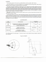
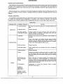
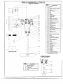
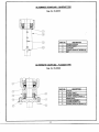
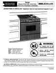
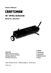
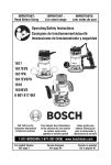
SERVICE INSTRUCTIONS
PORTABLE
MIXERS
3131 Casitas Avenue
Los Angeles, California 90039
Phone: (323) 664-1941 FAX: (323) 660-5677
www.mixmor.com
SERVICE INSTRUCTIONS
MODEL G & GA
GEAR DRIVEN PORTABLE MIXERS
MANUAL NO. 05-07884
CUSTOMER:
P.O. NO:
ITEM NO:
MIXMOR MODEL NO:
MIXER SERIAL NO:
MIXER H.P.:
BASEPLATEISEAL DWG. NO:
MIXER DWG. NO:
DATE:
3131 Casitas Avenue
Los Angeles, California 90039
Phone: (323) 664-1941
FAX: (323) 660-5677
www.mixmor.com
TABLE OF CONTENTS
PAGE
FOREWORD........................................................................................................I
GENERAL INFORMATION....................................................................................
.I
HANDLING INSTRUCTIONS.................................................................................
..I
SAFETY
HANDLING
INSTALLATION INSTRUCTIONS..........................................................................
-2-3
STORAGE
MOUNTING
GEAR REDUCER
MIXER SHAFT
IMPELLER
LOCATION
LUBRICATION INSTRUCTIONS..............................................................................4
GEAR REDUCER
CHANGING GREASE
GEAR REDUCER BEARINGS
START-UP INSTRUCTIONS...................................................................................5
GEAR REDUCER............................................................................................. ..6-7
PREVENTATIVE MAINTENANCE
TROUBLE SHOOTING
DISASSEMBLY AND ASSEMBLY
MIXER PARTS LIST DWG. NO. 05-07923............................................................... ..8
114 & 113 H.P. DRIVE
MIXER PARTS LIST DWG. NO. 05-02108.. ...............................................................9
112 THRU 5 H.P. DRIVE
ALTERNATE SHAFT COUPLINGS....................................................................10-11
SLEEVE COUPI-ING DWG. NO. 05-08370
FLANGE LOCK COUPLING DWG. 05-09508
MAINTENANCE RECORD...................................................................................
-12
FOREWORD
The information contained in this service instruction manual covers MixMor Model G portableclamp-on gear
driven mixers.
The model is determined by the type of motor on the mixer. The following are descriptions of the
models.
"G" - Electric motor driven, A.C. or D.C.
"GA" - Air motor driven, separate Operating and Maintenance Instructions for the air motor are included in
this manual.
Throughout 'this manual it will refer to drawing numbers which identify drives sizes, coupling designs, and
other mechanical details.The front page of this manual lists all the drawings that apply to your specific
mixer.
We have included informationin this manual that covers installation, start-up service, and trouble shooting to
assure years of reliable mixer service. Should questions or problems occur that are not covered in this manual,
consult your local representative or phone MixMor at either our Los Angeles, Ca.liforniaplant (213-664-1941)
or our King of Prussia, Pennsylvania plant (215-337-2700).
GENERAL INFORMATION
When apparent or suspected damage has been found on equipment, during transport from factory to user,
both the carrier and MixMor must be notified.
When receivingequipment, a check should be made to determine whether all inventoried parts are still in the
shipment. Any discrepancy should immediately be reported to both ,the carrier and MixMor, if claim is to
be made.
MixMor mixers do not require the service of a factory engineer upon installation.This service is not included
in the price of the unit; therefore, if it is to be furnished, it must be agreed upon, in writing, between MixMor and
the purchaser.
MixMor warranty becomesvoid if the unit sold is not operated within the ratingand mixing service conditions
for which it was specifically sold. The purchaser shall take all necessary precautions to eliminate all external
destructive conditions, including unusual variable loads affecting the critical speeds of the system, severe
shock loading, mechanical or thermal overloads and other conditions of which MixMor was not fully advised.
The mixer must be installed and maintained in accordance with this service manual.
MixMor must be informed within thirty days, for warranty to cover the mixer in the event of any malfunction
during the warranty period.
All personneldirectly responsiblefor operation of equipment must be instructedon proper installation,maintenance and safety procedures.
Design improvements are implemented on a continuous basis. Therefore, we reserve the right to make
changes without notice. If any questions arise regarding the data or information in this manual, please contact
MixMor in Los Angeles, California or King of Prussia, Pennsylvania.
HANDLING INSTRUC'TIONS
SAFETY
When handling or working on a MixMor mixer, safety precautions must always be remembered and
followed. The proper tools, clothing and methods of handling should be used to prevent any accidents.
This manual lists a number of safety precautions. Followthem. Insistthat your employees do the same. Safety
precautions and equipment have been developed from past accidents. Follow and use them for your
protection.
HANDLING
Do not support or lift the mixer in a manner which could create excessive stress on parts or shaft extensions.
Never allow shafting to support any weight of the drive assembly. A slightly bent shaft will cause extreme mixer
vibration. Support the mixer with a lifting sling to prevent damaging of any external parts.
INSTALLATION INSTRUCTION
REFER TO DWG. NO. 05-07923 or 05-02108
STORAGE
If installation of the mixer and/or operation is to be delayed for more than one month after factory
shipment, special rust preventative precautions should be taken. The precautions may be taken by the
user or by the factory if full information concerning storage conditions is provided at the time of ordering.
MOUNTING
Position the niixer clamp on the mounting surface with the base and inside face making full contact.
Securely tighten the star wheel screw (14). Do not use an extension.
GEAR REDUCER
The mixer is shipped from the factory with a completely assembled gear drive. Gearing is carefully
assembled at the factory to provide gear contact. Do not change the setting in any way.
When shipped, the gear reducer has been filled with the proper lubricating grease and does not have to
be serviced before start-up. We recommended that you read the LUBRICATION INSTRUCTIONS before
start-up to familiarize yourself with the mixer.
MIXER SHAFT
Handle the shaft carefully and always place it in a horizontal position, supporting it at several points.
Check the shaft for nicks or burrs.
Align the shaft keyway with the key and slide the shaft as far as it will go into the quill shaft and tighten
socket head cap screw (28). Refer to pages 10 and 11 for alternate shaft coupling instructions.
IMPELLER
When mixers are furnished with two impellers the upper impeller should be positioned midway between
the lower impeller and the normal liquid level. I f one of the impellers has a stabilizing on it, it must be
used as the lower impeller and attached to the end on the shaft with the stabilizing ring down. Position the
impellers on the shaft and tighten the hex head set screws. Depending on the severity of the application, it
may be advisable to spot drill the shaft for the impeller set screws.
LOCATION
The mounting position of the mixer has a definite effect on the flow pattern within the tank.
The correct position for your mixer will depend on your application and the tank geometry. After start-up,
adjustment may be required to achieve optimum mixing results.
The location chart gives guidelines for positioning your mixer. When the mixer shaft is angled to the right of
horizontal tank centerline, a top-to-bottom flow pattern will be achieved, which is well-suited for most mixing
applications. Positioning the shaft on center with the tank centerline will create a vortex which may be helpful in
wetting or introducing light solids. Positioning the shaft to the left of the tank centerline will produce a swirling
flow pattern which may be useful when blending high-viscosity products. Do not be hesitant to try various
positions before deciding on the optimum location.
Warning! Do not attempt to change the positionwhile the mixer is running.Always disconnect power to the
mixer before making a change.
To change the position of the mixer, loosen the wedge lock screw (1 3) and move the drive into the desired
positionand tighten the wedge lock screw. The sliding wedge (09)has a limited amount of travel and can topout
against the hex bolt (06) before the drive can be securely locked to the clamp. If this happens, remove the
wedge lock screw (13) and tighten hex nut (07) until the drive can just be moved in the clamp socket. Replace
the wedge lock screw and tighten it.
LOCATION CHART
FLOW
PATTERN
APPLICATION
TOP
TO
BOTTOM
CONVENTIONAL POSITION. MOST BLENDING
AND SOLID SUSPENSION APPLICATION,
VARIOUS VISCOSITIES
VORTEXING
VORTEX TO WET OR
DISPERSE LIGHT SOLIDS
SWIRLING
BLEND-INGOF SOME
HIGH VISCOSITY PRODUCTS
"A"
POSITION
"H"
"I"
10-30"
5-20"
ON-CENTER
10-30"
5-20"
5-20"
The vertical angle of the shaft (angle "I") should not reach a point where the lower impeller contacts the
tank centerline.
Dwg. No. 05-08422
LUBRICATION
GEARREDUCER
All portable mixers are shipped from the factory with the gear reducers filled with the proper lubricating
grease. The grease should be changed every five years, when used under normal operating conditions, and/or
whenever repair work is performed. If the mixer is operating in extremely dirty, or high or low temperature
environments,the grease s h o ~ ~be
l dchanged moreoften. If you or your lubricantsupplier are uncertainas to the
frequency of changes, please consult MixMor for our recommendation for your specific environment.
CHANGING GREASE
Refer to dwg. No.05-02108 or No.05-07923. Removethe mixer shaft (29)from the drive. Remove hex nut (7)
and separate the clamp assembly from the gear housing (5). Remove socket head cap screws (22 & 16) and
separatethe motor (1)and quill housing (23)from the gear housing. Removeall grease and clean all parts with a
non-flammable, non-toxic solvent. Refill the gear housing with grease. Refer to the following charts for
approved lubricant recommendation and gear housing grease capacity.
APPROVED LUBRICANTS
LUBRICANT
MANUFACTURER
Shell
Mobil
Arco
Texaco
Chevron
BRAND NAME
Darina EP 0 or
Alvar~iaEP RO
Sovarex L
Olaline Grease 0
Novatex EP 0
EP Roller Grease OX
APPROXIMATE GREASE 'CAPACITY
DRAWING NO.
H.P.
05-07923
114 8 113
05-02108
112-5
WEIGHT
Ib- Oz.
2 1bs. 12 oz.
GEAR REDUCER BEARINGS
All the bearings in the gear reducer are permanently lubricated, double sealed and do not require
additional lubrication.
START-UP INSTRUCTIONS
When starting up any new piece of equipment, it is wise to proceedcautiously. Even though the best installation practices are followed, the possibilities of errors or omissions always exist. Mixmor recommends that
before the initial start-up, the following checklist should be followed:
1. Has all accessory equipment such as: breathers, level indicators, switches, etc., been mounted? It is often
necessary to box these items separately to prevent damage or loss in shipment.
2.
Is the mountingclamp tight? Check all external bolts, screws, accessories, etc., to make sure they have not
become loose in shipping and handling.
3. Have required electrical connections been made? Units should be wired in accordance with motor
manufacturer's wiring diagram on the motor.
During start-up, the following procedures are recommended to assure years of trouble-free operation:
'
1. Start mixer slowly under as light a load as possible.Check the rotation of the shaft against the rotationarrow
on the mixer housing. If necessary,reverse electrical leads on motor to have shaft rotation conform to direction shown on mixer.
2. As the mixer is brought up to normal operating speed, it should be checked for unusual sounds, excessive
vibrations, excessive heat or grease leakage. If any of these develop, .the unit should be shut down
immediately and the cause determined and corrected. The operating temperature of the unit at the hottest
point normally should not exceed 200" F.
3.
If possible, the mixer should be operated under a light load (approximatelyhalf-load)for one or two days to
allow final breaking-in of gears. After this period, the unit can be operated under normal load.
4.
After the first 48 hours of operation, all external housing and mounting fasteners should be checked for
tightness. Loose fasteners can cause problems and excessive wear.
GEAR REDUCER
PREVENTKrIVE MAINTENANCE
Keep shafts and vent plug clean to prevent foreign particles from entering sea.lsor gear case. Never paint the
vent plug. Check coupling set screws and all fasteners for tightness. Loose fasteners will cause alignment
problems and excessive wear. Check end play in shaft. Noticeable movement might indicate service or
parts replacement.
When lip seals are new, a small amount of lubricant leakage is sometimes noted until the seals seat on the
shaft. This condition is normal. However, if leakage persists, this indicates a damaged seal and it must be
replaced.
TROUBLE SHOOTING
It is advisable to periodically inspect your gear drive for signs of wear. Spare or replacement parts can often
be ordered and obtained before disassembly is necessary, thus minimizing downtime. The following
symptoms can be visually inspected without disassembly and may, in some cases, require repair work.
'
CHECKLIST
OBSERVA1-ION
VIBRATION
ACT I0N
POSSIBLE SOURCE
1) Loose hardware
Be certain all external housing and mounting fasteners are
tight.
2) Bearing failure
Replace bearings
3) Foreign particles
in bearings and gears
Foreign particles will cause excessive wear. Take steps to
prevent entrance of particles. Thoroughly flush drive with
solvent and refill with new grease.
1) Breather
Breather must be free of any obstruction. Clean breather as
required.
2) Overloaded
Check mixer speed and impeller diameter against certified
drawing. Has the specific gravity and/or viscosity of the
product increased? Inspect for material build-up on impeller.
Check shaft rotation against rotation arrow.
3) Bearing failure
Replace bearings.
4) Reducer grease
Check grease level and condition and add or change as
required.
1) Bearing failure
Replace bearings.
2) Rust
Rust can be caused by entrance of water or humidity. Flush
and thoroughly clean drive. Take steps to prevent further
entrance of water and use a lubricant with good rust-inhibiting
properties.
3) Extended shutdown or improper
storage
When drives are not properly prepared for extended shutdown or storage in a moist atmosphere or a temperature
condition which will cause condensation, destructive rusting
of bearings, gears and shaftslseals will take place. Clean and
replace parts as required.
4) Overloaded
Overloading can cause loud operation. Refer to OVERHEATING, Source No. 2.
OVERHEATING
NOISE
5) Refer to
VIBRATION
Source No. 3
6) Refer to OVERHEATING, Sources
No.3 2 & 4
GREASE
LEAKINGS
1) Worn lip seals
Replace defective seals.
2) Plugged breather
Breather must be free of any obstructions. Clean breather
as required.
3) Gear case joints
Tighten fasteners or remove and recoat with Locktite before
tightening. If this does not stop leakage, remove housing,
clean surfaces and replace gaskets or apply new sealing
compound.
DISASSEMBLY AND ASSEMBLY
Never perform any work on the gear reducer or coupling until you are absolutely certain that the prime mover
to keep parts clean
cannot be remotely or automatically started. Clean up area around unit before disasserr~bly
and to keep them in proper order for re-assembly. Keep in mind that parts usually go back together in reverse
order of disassembly. Provide wooden blocks for storing machined parts in order to prevent damage to
machine surfaces. Before starting disassembly, carefully review typical parts list and assembly drawing of
unit.
Refer to Dwg. No. 05-07923 or 05-02108
1. Disconnect the power to the motor. Be certain that the mixer cannot be remotely or automatically
started.
2.
Disconnect and, if necessary, remove the mixer shaft (29) from the drive.
3. Remove hex nut (7) and separate the clamp assembly from the gear housing (5).
4.
Remove socket head cap screws (22)and remove reducer shaft housing(23)with the shaft assembly from
the gear housing.
5.
Remove retaining ring (17) and pull gear (18) off of quill shaft (24). Remove retaining ring (19). The reducer
quill shaft (24), with bearing and seals, can now be pressed out of the housing (23).
6.
Removesocket head cap screws (16) and remove motor (1)from gear housing (5). Loosensocket head set
screws (3) and remove pinion (4) from motor shaft.
7. Clean all parts thoroughly. Beforeassembly,examinecomponents carefullyfor signs of wear and replace if
necessary.
8. Reverse the preceding instructions for assembly. Be certain to position the pinion (4.) on the motor shaft to
the dimension shown on the drawing. This will insure full gear (18) face contact with the pinion.
The sliding wedge (9) has a limited amount of travel and can top out against the hex bolt (6) before the drive
can be securely locked to the clamp. If this happens, remove the wedge lock screw (13) and tighten hex nut (7)
until the drive can just be moved in the clamp socket. Replace the wedge lock screw and tighten it.
MODEL G & GA MIXER PARTS. 1/4 AND 1/3 H.P.
Dwg. NO.05-07923
MODEL G & GA MIXER PARTS. 1/2 THRU 5 H.P.
Dwg. No. 05-02108
I
(REPLACES CLAMP)
RECOMMENDED SPARE PARTS
ALTERNATE COUPLING
I
PART
NO.
1
Dwg. No. 05-08370
DESCRIPTION
BEARING SPACER
2
OUTPUT SHAFT
3
COLlPLlNG
4
SOCKET HEAD SET SCREW (8)
5
KEY
9
FLANGE LOCK COUPLING
DISASSEMBLY AND ASSEMBLY
DWG. NO.05-09508
The flange ring coupling assembly is a keyless shaft-flange coupling connector providing
mechanically the same characteristic as a shrink fit. It is, however, easily adjustable and
removable thus facilitating simple assembly and disassembly. Since torque is transmitted by
friction between functional surface, condition of contact surfaces and proper tightening of the
locking screws are of great importance.
DISASSEMBLY
1. Disconnect the mixer shaft (5) from the drive, by removing the socket head cap screws (8)
2. Loosen locking screws (7) in several stages by aprox. % turns, following a diametrical
opposite sequence.
NOTE: Locking assemblies feature self-releasing tapers.
However, if for some reason thrust rings jam, a light tap on 3 equally spaced heads of loosened
screws will positively release connection.
3. Although flange coupling (3) and locking assembly (6) are normally removed together,
removal of locking assembly (6) only from deep counterbores is accomplished by inserting
pull out screws in threads located under cadmium plated locking screws (4).
ASSEMBLY
DO NOT USE MOLYDEBUM-DISULFIDE. e.a.. MOLYKOTE OR NEVER-SEEZE.
1.
Insert locking assembly (6) into flange coupling (3) and slide it onto output shaft (2).
2.
After checking correct flange coupling position, handtighten 3 or 4 equally spaced locking
screws (7) un1:il initial contact is established.
3.
Use torque wrench and set it approximately 11.5 ft-lb. Torque screws in either a clockwise or
counter clockwise sequence, using only % turns (it is not necessary to tighten in a
diamet~icallyopposite pattern) for several passes until % turns can no longer be achieved.
4.
Still apply overtorque for 1 or 2 more passes. This is required to compensate for a systemrelated relaxation of locking screws since tightening of a given screw will always relax
adjacent screws. Without overtorquing, an infinite number of passes would be needed to
reach specified tightening torque.
5.
Reset torque wrench to 11 ft-lb. and check all locking screws. No screw should turn at this
point, othewise repeat step "4" for 1 or 2 more passes. It is not necessary to recheck
tightening toque after equipment has been in operation.
'
ALTERNATE COUPLING - SLEEVE TYPE
Dwg. No. 0508370
I
1
PART NO.
DESCRIPTION
1
BEARING SPACER
4
5
SOCKET HEAD SET SCREW (8)
IKM
ALTERNATE COUPLING - FLANGE TYPE
Dwg. NO. 05-09508
DESCRIPTION
OUTPUT SHAFT
FLANGE COUPLING
6
ILOCKING ASSEMBLY
- - - . ....- - ,
HEAD CAP SCREW (4)
-
8
SOCKET
.
I
MAINTENANCE RECORD
Date
WORK PERFORMED
-
P
A
-
--- ---
.-
- --
-
-
----
-
.
- .-----
NOTES