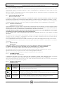
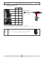
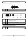
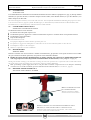
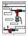
1
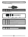
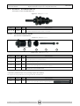
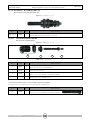
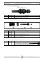
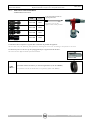
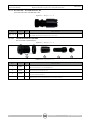
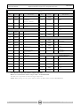
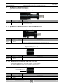
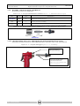
Manuale Istruzioni Instruction Manual Tirainserti oleopneumatica per inserti M3/M12 HydroPneumatic tool for inserts from M3 to M12 MANUALE RIV 998 V ISTRUZIONI INSTRUCTION MANUAL CODICE/CODE 37675 RIV 998 V TIRAINSERTI OLEOPNEUMATICA PER INSERTI da M3 a M12 HYDRO-PNEUMATIC TOOL FOR INSERTS FROM M3 TO M12 Rivit S.r.l. Via Marconi, 20 – loc. Ponte Rizzoli 40064 Ozzano dell’Emilia (Bologna) - Italy : ++39 051 417 11 11 :++39 051 417 11 29 www.rivit.it -- rivit@rivit.it Rev. 0 del 01/02/2012 TIMBRO DISTRIBUTORE AUTORIZZATO STAMP OF THE AUTHORISED DEALER Manuale Istruzioni Instruction Manual Tirainserti oleopneumatica per inserti da M3 a M12 Hydro-Pneumatic tool for rivets nut from M3 to M12 RIV 998 V ATTENZIONE!!!!! LA RIV 998 V VIENE FORNITA SENZA KIT. SONO DA CHIEDERE A PARTE SECONDO LE ESIGENZE DELL’UTILIZZATORE. WARNING !!!!! RIV 998 V COMES WITHOUT KITS. KITS HAVE TO BE ORDERED SEPARATELY ACCORDING TO THE USER NEEDS. 2 www.rivit.it Rev. 0 del 01/02/2012 Manuale Istruzioni Instruction Manual Tirainserti oleopneumatica per inserti M3/M12 HydroPneumatic tool for inserts from M3 to M12 RIV 998 V INDICE/CONTENTS 1 - INFORMAZIONI GENERALI GENERAL INFORMATION PAG. 5 1.1 COSTRUTTORE/MANUFACTURER 1.2 ASSISTENZA/ASSISTANCE 1.3 CERTIFICAZIONE E MARCATURA CE/CERTIFICATION AND EC MARKING 1.4 GARANZIA/WARRANTY 1.5 STRUTTURA DEL MANUALE/MANUAL STRUCTURE 1.5.1 SCOPO E CONTENUTO/PURPOSE AND CONTENTS 1.5.2 DESTINATARI/RECEIVERS 1.5.3 CONSERVAZIONE/PLACING OF THE MANUAL 1.5.4 SIMBOLI UTILIZZATI/SYMBOLS USED 2 - DESCRIZIONE MACCHINA TOOL DESCRIPTION PAG.7 2.1 PRINCIPIO DI FUNZIONAMENTO/OPERATING SYSTEM 2.2 VIBRAZIONI/VIBRATION 2.3 EMISSIONI SONORE/NOISE LEVEL 2.4 DATI TECNICI/TECHNICAL DATA 2.5 EQUIPAGGIAMENTO E ACCESSORI STANDARD/NOSE ASSEMBLIES AND STANDARD ACCESSORIES 2.5.1 KIT 998/A: KIT TESTATA SPECIALE PROLUNGA A RICHIESTA NON COMPRESA NELL’EQUIPAGGIAMENTO STANDARD/KIT 998/A: KIT FOR SPECIAL NOSE. EXTENSION ON REQUEST: NOT INCLUDED IN THE STANDARD ACCESSORIES 2.5.1.1 COMPOSIZIONE KIT 998/A/KIT 998/A COMPOSITION PLACING 2.5.3.1 KIT 998V/04B – KIT PER RIVBOLT M4 /KIT 998V/04B – KIT FOR RIVBOLT M4 2.5.3.1.1 COMPOSIZIONE KIT 998V/04B /KIT 998V/04B COMPOSITION 2.5.3.2 KIT 998V/05B – KIT PER RIVBOLT M5 /KIT 998V/05B – KIT FOR RIVBOLT M5 2.5.3.2.1 COMPOSIZIONE KIT 998V/05B /KIT 998V/05B COMPOSITION 2.5.3.3 KIT 998V/06B – KIT PER RIVBOLT M6 /KIT 998V/06B – KIT FOR RIVBOLT M6 2.5.3.3.1 COMPOSIZIONE KIT 998V/06B /KIT 998V/06B COMPOSITION 2.5.3.4 KIT 998V/08B – KIT PER RIVBOLT M8 /KIT 998V/08B – KIT FOR RIVBOLT M8 2.5.3.4.1 COMPOSIZIONE KIT 998V/08B /KIT 998V/08B COMPOSITION 3 - RICAMBI SPARE PARTS PAG.24 3.1 PARTI DI RICAMBIO/SPARE PARTS 3.1.1 KIT RAPIDO COMPLETO DI MOLLA/ QUICK KIT COMPLETE WITH SPRING 3.1.2 KIT RAPIDO COMPLETO DI MOLLA SENZA GHIERA DENTATA/ QUICK KIT COMPLETE WITH SPRING WITHOUT TOOTHED RING NUT 2.5.2 PER APPLICAZIONE RIVSERT/FOR RIVSERT PLACING 2.5.2.1 KIT 998V/03 – KIT PER RIVSERT M3 /KIT 998V/03 – KIT FOR RIVSERT M3 2.5.2.1.1 COMPOSIZIONE KIT 998V/03 /KIT 998V/03 COMPOSITION 2.5.2.2 KIT 998V/04 – KIT PER RIVSERT M4 /KIT 998V/04 – KIT FOR RIVSERT M4 2.5.2.2.1 COMPOSIZIONE KIT 998V/04 /KIT 998V/04 COMPOSITION 2.5.2.3 KIT 998V/05 – KIT PER RIVSERT M5 /KIT 998V/05 – KIT FOR RIVSERT M5 2.5.2.3.1 COMPOSIZIONE KIT 998V/05 /KIT 998V/05 COMPOSITION 2.5.2.4 KIT 998V/06 – KIT PER RIVSERT M6 /KIT 998V/06 – KIT FOR RIVSERT M6 2.5.2.4.1 COMPOSIZIONE KIT 998V/06 /KIT 998V/06 COMPOSITION 2.5.2.5 KIT 998V/08 – KIT PER RIVSERT M8 /KIT 998V/08 – KIT FOR RIVSERT M8 2.5.2.5.1 COMPOSIZIONE KIT 998V/08 /KIT 998V/08 COMPOSITION 2.5.2.6 KIT 998V/10 – KIT PER RIVSERT M10 /KIT 998V/10 – KIT FOR RIVSERT M10 2.5.2.6.1 COMPOSIZIONE KIT 998V/10 /KIT 998V/10 COMPOSITION 2.5.2.7 KIT 998V/12 – KIT PER RIVSERT M12 /KIT 998V/12 – KIT FOR RIVSERT M12 Rev. 0 del 01/02/2012 2.5.2.7.1.1 COMPOSIZIONE KIT 998V/12 /KIT 998V/12 COMPOSITION 2.5.3 PER APPLICAZIONE RIVBOLT/FOR RIVBOLT www.rivit.it 3.1.2.1 GHIERA DENTATA SPECIALE PER VITE TCCEI M8. NON NECESSITA DELLA RIDUZIONE (COD. RIVIT 34726) (ACCESSORIO A RICHIESTA)/SPECIAL TOOTHED RING NUT FOR SOCKET CAP SCREWM8.NO NEED FOR REDUCTION (RIVIT CODE 34726) (OPTIONAL) 3.2 PARTI DI RICAMBIO DEL GRUPPO MOTORE (60)/SPARE PARTS OF THE MOTOR UNIT (60) 3.3 ORDINAZIONE RICAMBI/ORDERING SPARE PARTS 4 - SICUREZZA SAFETY PAG.29 4.1 AVVERTENZE GENERALI/GENERAL WARNINGS 4.2 USO PREVISTO/INTENDED USE 4.3 CONTROINDICAZIONI D’USO/OPERATING CONTAINDICATIONS 4.4 RISCHI RESIDUI/RESIDUE RISKS 4.5 IDENTIFICAZIONE/MATRICOLA/ IDENTIFICATION/SERIAL NUMBER 5 - INSTALLAZIONE INSTALLATION PAG.31 5.1 TRASPORTO E MOVIMENTAZIONE/TRANSPORT AND HANDLING 5.2 STOCCAGGIO/STORAGE 5.3 COLLEGAMENTI/CONNECTIONS 5.3.1 PNEUMATICO/PNEUMATIC CONNECTION 5.4 ALIMENTAZIONE DELL’ARIA/AIR SUPPLY 5.5 CONTROLLI PRELIMINARI/PRELIMINARY CHECKS 3 Manuale Istruzioni Instruction Manual Tirainserti oleopneumatica per inserti da M3 a M12 Hydro-Pneumatic tool for rivets nut from M3 to M12 6 - FUNZIONAMENTO OPERATION PAG.33 6.1 ADDETTI/OPERATORS 6.2 PREPARAZIONE DELLA MACCHINA/TOOL PREPARATION 6.3 MESSA IN FUNZIONE/PUTTING INTO SERVICE 6.4 REGOLAZIONE DELLA CORSA/STROKE ADJUSTMENT 6.5 CAMBIO DELLA VITE/SCREW REPLACEMENT 7 - MANUTENZIONE SERVICING THE TOOL PAG.37 7.1 STATO DI MANUTENZIONE/MAINTENANCE STATUS 7.2 PULIZIA/CLEANING 7.3 MANUTENZIONE ORDINARIA/ORDINARY MAINTENANCE 7.3.1 RIPRISTINO OLIO CIRCUITO OLEODINAMICO/FILLING THE HYDRAULIC CIRCUIT WITH OIL (WHEN RUN OUT) 7.3.2 KIT PER LA MANUTENZIONE A RICHIESTA/MAINTENANCE KIT ON REQUEST 7.3.2.1 PROSPETTI RELATIVI ALLA PREPARAZIONE, MANUTENZIONE, MONTAGGIO/DETAILED 4 RIV 998 V INSTRUCTIONS ON TOOL PREPARATION, MAINTENANCE AND ASSEMBLING 7.3.2.2 CHIAVI VARIE COMMERCIALI E SPECIALI PER MANUTENZIONE ORDINARIA E OLIO A RICHIESTA/COMMERCIAL AND SPECIAL WRENCEHS FOR ORDINARY SERVICE AND OIL ON REQUEST 7.3.3 PARTI SOTTOPOSTE AD AZIONE DI USURA/PARTS SUBJECT TO WEAR 8 - DIAGNOSTICA E RIPARAZIONI FAULT DIAGNOSIS AND REPAIRS PAG.42 8.1 RIPARAZIONI/REPAIRS 8.2 RICHIESTA DI ASSISTENZA/REQUESTING ASSISTANCE 9 - DEMOLIZIONE DISMANTLING INSTRUCTIONS PAG.42 9.1 DEMOLIZIONE DELLA MACCHINA/DISMANTLING INSTRUCTIONS 10 - ALLEGATI ENCLOSED DOCUMENTS 10.1 DICHIARAZIONE/DECLARATION www.rivit.it PAG.42 Rev. 0 del 01/02/2012 Manuale Istruzioni Instruction Manual Tirainserti oleopneumatica per inserti da M3 a M12 Hydro-Pneumatic tool for rivets nut from M3 to M12 RIV 998 V 1 - INFORMAZIONI GENERALI GENERAL INFORMATION 1.1 - COSTRUTTORE MANUFACTURER La ditta Rivit S.r.l. è nata nel 1973, produce e distribuisce Fasteners e attrezzi per il fissaggio (rivettatrici, tirainserti). Vanta un’esperienza tecnica e può offrire un’ampia gamma di prodotti inerenti ai sistemi di fissaggio. Rivit S.r.l. was born in 1973, it produces and distributes Fasteners and Tools for Fixings (tools for rivets and rivet nuts). The Company boasts much technical experience and offers a wide range of products related to fastening systems. TEL/PHONE ++39 051 4171111 FAX ++39 051 4171129 1.2 - ASSISTENZA ASSISTANCE Per qualsiasi necessità inerente l’uso, la manutenzione o la richiesta di parti di ricambio, il Cliente è tenuto a rivolgersi al distributore di zona autorizzato (oppure direttamente alla Rivit S.r.l.), specificando i dati identificativi della Macchina riportati sul cilindro esterno: In case you need any assistance concerning the use and the maintenance of the tool, or in case you need to order any spare parts, you shall contact your local authorised dealer (or Rivit S.r.l. directly) specifying the identification/serial numbers of the tool, written on its outer casing: C1 Vedere paragrafo 3 See section 3 1.3 - CERTIFICAZIONE E MARCATURA CE CERTIFICATION AND EC MARKING La Macchina è realizzata in conformità delle Direttive Comunitarie pertinenti ed applicabili nel momento della sua immissione sul mercato. Non rientrando la Macchina nell’ALLEGATO IV della DIRETTIVA 98/37/CE, la Rivit S.r.l. provvede alla Autocertificazione per apporre la marcatura CE. The tool is manufactured in compliance with the European Directives, which are in force when the tool itself is put on the market. As the tool is not included in ENCLOSURE IV of DIRECTIVE 98/37/EEC, Rivit S.r.l. issues a self-certification to apply the EC marking. 1.4 - GARANZIA WARRANTY Il periodo di garanzia è di 12 mesi dalla data riportata sulla relativa Fattura o Bolla di Consegna. La Garanzia comprende esclusivamente le parti sostituite, con esclusione della mano d’opera. Non sono compresi nella Garanzia, sia gli accessori standard (vedere paragrafo 2.5 pag. 7) sia i danni alla Macchina causati da: trasporto e/o movimentazione errori dell’Operatore mancata manutenzione prevista dal presente Manuale (vedere capitolo 7) guasti e/o rotture non imputabili al malfunzionamento della stessa normale consumo delle parti soggette ad usura. La manomissione/sostituzione non autorizzata di parti della macchina, l'uso di accessori, di utensili, di materiali di consumo diversi da quelli raccomandati dal costruttore potrebbero rappresentare un pericolo di infortunio e sollevano il costruttore dalla garanzia. La Rivit si assume la responsabilità solo se la macchina è difettosa all'origine e decade se l'utilizzatore non si adegua alle istruzioni fornite. The warranty has a validity of 12 months, as of the date indicated on the invoice. The warranty only covers replaced parts; labour is not included. The following are not covered by warranty: standard accessories (see section 2.5, page 7) and tool damages caused y transport and/or handling, user’s mistakes, failed servicing/maintenance, as indicated in section 7 of this manual, faults and/or breakages that are not attributable to tool anomalies, Rev. 0 del 01/02/2012 www.rivit.it 5 Manuale Istruzioni Instruction Manual Tirainserti oleopneumatica per inserti da M3 a M12 Hydro-Pneumatic tool for rivets nut from M3 to M12 RIV 998 V normal consumption of consumables. The warranty is invalidated both in case of unauthorised tampering/replacements of tool components and in case of use of accessories, tools or consumables different to those recommended by the manufacturer, which could even cause injuries to the tool’s user. Rivit S.r.l. assumes responsibilities only if the tool is originally defective, but declines all forms of responsibility if the user fails to follow the instructions given. 1.5 - STRUTTURA DEL MANUALE MANUAL STRUCTURE Il Cliente deve leggere con estrema attenzione le informazioni riportate nel presente Manuale, in quanto una corretta Predisposizione, Installazione ed Utilizzazione della Macchina, costituiscono la base del rapporto Costruttore - Cliente. This instruction manual must be read with particular attention by the Customer, as the correct pre-arrangement, installation and use of the tool, are the correct basis for a good relationship between Manufacturer and Customer. 1.5.1 - SCOPO E CONTENUTO PURPOSE AND CONTENTS Questo Manuale ha lo scopo di fornire al Cliente tutte le informazioni necessarie affinché, oltre ad un adeguato utilizzo della Macchina, sia in grado di gestire la stessa nel modo più autonomo e sicuro possibile. Esso comprende informazioni inerenti l'aspetto Tecnico, il Funzionamento, la Manutenzione, i Ricambi e la Sicurezza. Prima di effettuare qualsiasi operazione sulla Macchina, gli Operatori ed i Tecnici Qualificati devono leggere attentamente le istruzioni contenute nella presente pubblicazione. In caso di dubbi sulla corretta interpretazione delle istruzioni, interpellare la Rivit S.r.l. per ottenere i necessari chiarimenti. The manual herein has the purpose of providing the Customer with all the information needed not only to use the tool correctly, but also to manage it self-sufficiently and safely. It includes information concerning technical aspects, operation, maintenance, spare parts and safety. Users and Qualified Technicians must read the instructions given herein thoroughly before starting to use the tool. If you have any doubts on the meaning of the instructions given, please do not hesitate to contact Rivit S.r.l. for further explanations. 1.5.2 - DESTINATARI RECEIVERS Il Manuale in oggetto è rivolto sia all'Operatore che ai Tecnici abilitati alla Manutenzione della Macchina. I Conduttori non devono eseguire operazioni riservate ai Manutentori o ai Tecnici qualificati. La Rivit S.r.l. non risponde di danni derivanti dalla mancata osservanza di questo divieto. The manual herein has been written for both the operators and the technicians enabled to service the tool. Operators must not carry out jobs reserved to service and/or qualified technicians. Rivit S.r.l. is not liable for any damage deriving from the failed observance of this rule. 1.5.3 - CONSERVAZIONE PLACING OF THE MANUAL Il Manuale di Istruzioni deve essere conservato nelle immediate vicinanze della Macchina, dentro un apposito contenitore e, soprattutto, al riparo da liquidi e quant'altro ne possa compromettere lo stato di leggibilità. This instruction manual must be kept near the tool, inside a dedicated container and, above all, away from liquids or anything else that may compromise its legibility. 1.5.4 - SIMBOLI UTILIZZATI SYMBOLS USED SIMBOLO SIGNIFICATO SYMBOL MEANING P ... PERICOLO HAZARD AVVERTENZA WARNING A ... C ... 6 COMMENTO COMMENT Indica un pericolo con rischio per l'Utilizzatore. This highlights a hazard with risk for the user. Indica un’avvertenza o una nota su funzioni chiave o su informazioni utili. Prestare la massima attenzione ai blocchi di testo indicati da questo simbolo. This points out a warning/note on key functions or useful information. Read the texts indicated by this symbol with utmost attention. CONSULTAZIONE Occorre consultare il Manuale Istruzioni prima di effettuare una determinata operazione. CONSULT Consult the instruction manual before carrying out a specific procedure. www.rivit.it Rev. 0 del 01/02/2012 Manuale Istruzioni Instruction Manual Tirainserti oleopneumatica per inserti da M3 a M12 Hydro-Pneumatic tool for rivets nut from M3 to M12 RIV 998 V 2 - DESCRIZIONE MACCHINA TOOL DESCRIPTION 2.1 - PRINCIPIO DI FUNZIONAMENTO OPERATING SYSTEM La Tirainserti oleopneumatica, RIV 998 V, viene utilizzata con: inserti filettati femmine RIVSERT, da M3 a M12, inserti filettati maschi RIVBOLT, da M4 a M8, Il sistema oleopneumatico utilizzato e le parti meccaniche che compongono la struttura interna della RIV 998 V, rispetto ad altri modelli di tirainserti, danno un’ottima affidabilità in riduzione dei problemi dovuti all’usura dei componenti, con conseguente aumento di durata e funzionalità. Le soluzione tecniche adottate riducono le dimensioni e il peso della macchina rendendo la RIV 998 V assolutamente maneggevole. The hydro-pneumatic RIV 998 V type tool is designed to place the following fasteners: RIVSERT female threaded inserts (from M3 to M12) RIVBOLT male threaded inserts (from M4 to M8) The hydro-pneumatic system and the mechanical components used in the inside structure of the RIV 998 V, when compared with other riveting tools, result to be much more reliable. A tool feature is a reduction of the problems caused by the wear and tear of the components, and consequently the tool will last much longer and work better. The technical solutions adopted make the RIV 998 V more compact and lighter: the result is a very handy tool. 2.2 - VIBRAZIONI VIBRATION In condizioni di impiego conformi alle indicazioni di corretto utilizzo, le vibrazioni non sono tali da fare insorgere situazioni di pericolo. When used correctly, i.e. in compliance with the instructions given, the tool does not produce any dangerous vibration. 2.3 - EMISSIONI SONORE NOISE LEVEL La Macchina è progettata e realizzata in modo da ridurre alla sorgente il livello di emissione sonora; infatti il livello di pressione acustica continuo equivalente ponderato A nel posto di lavoro dell'operatore non supera 80 dB (A). In ogni caso, le informazioni citate, consentiranno all’Utente della Macchina di effettuare una migliore valutazione del pericolo e del rischio a cui è sottoposto. The tool is designed and manufactured in such a way that the noise level results to be very low. The weighed equivalent continuous acoustic pressure level A in the operator position is indeed below 80 dB (A). The information given can, in any event, allow the tool user to better evaluate the possible and eventual risks of danger. Rev. 0 del 01/02/2012 www.rivit.it 7 Manuale Istruzioni Instruction Manual Tirainserti oleopneumatica per inserti da M3 a M12 Hydro-Pneumatic tool for rivets nut from M3 to M12 RIV 998 V 2.4 - DATI TECNICI TECHNICAL DATA Di seguito sono riportati i dati e le caratteristiche tecniche della Macchina a cui occorre fare riferimento per ogni eventuale contatto con l'Assistenza Tecnica della Rivit S.r.l.. The following table provides the technical data and features of the tool, to which you must refer when contacting the Technical Assistance Department of Rivit S.r.l.. TABELLA 2. 4 A - DATI E CARATTERISTICHE/TABLE 2. 4 A - TECHNICAL DATA AND FEATURES PRESSIONE ARIA DI ESERCIZIO/AIR WORKING PRESSURE 6 bar PRESSIONE ARIA MIN – MAX/MIN – MAX AIR PRESSURE 5 – 7 bar CONSUMO ARIA PER CICLO A 6 BAR/AIR CONSUMPTION PER CYCLE AT 6 BAR 7,5 litri CORSA/STROKE 0 - 6,5 mm FORZA DI TRAZIONE A 6 BAR/DRIVING FORCE AT 6 BAR 21.000 N PESO (senza 2,4 Kg equipaggiamento)/WEIGHT (w/o equipment) VIBRAZIONI/VIBRATIONS < 2,5 m/s2 RUMOROSITA'/NOISE LEVEL < 80 dB (A) 2.5 - EQUIPAGGIAMENTO E ACCESSORI STANDARD NOSE ASSEMBLIES AND STANDARD ACCESSORIES Gli equipaggiamenti di seguito citati, sono riferiti a Macchine facenti parte della Produzione di serie. Eventuali forniture speciali, potrebbero, di conseguenza, richiedere particolari diversi da quelli elencati. The nose assemblies stated hereafter refers to standard tools. Any special tool could consequently require special parts, different to those listed. Figura 2.5 – A/Figure 2.5 – A RIF. REF. CODICE Q.TÀ CODE Q.TY DESCRIZIONE DESCRIPTION RIV 998 V-TIRAINSERTI OLEOPNEUMATICA RIV 998 V-HYDROPNEUMATIC TOOL Fig.2.5-A 37675 1 RIV 998 V-TIRAINSERTI OLEOPNEUMATICA IN CASSETTA RIV 998 V-HYDRO-PNEUMATIC TOOL FOR INSERT (IN PVC CASE) 64. 25338 1 PERNO REGOLAZIONE CORSA E EMERGENZA EMERGENCY AND STROKE REGULATION PIN 65. 02073 1 CHIAVE UNIVERSALE UNIVERSAL KEY 67. 30644 1 OLIO IDRAULICO TIPO ISO VG 32 100CC HYDRAULIC OIL TYPE ISO VG 32 100CC 68. 03698 1 VALIGIA IN PLASTICA PLASTIC CASE - - 1 MANUALE DI ISTRUZIONI INSTRUCTION MANUAL 65 67 68 64 8 www.rivit.it Rev. 0 del 01/02/2012 Manuale Istruzioni Instruction Manual 2.5.1 - Tirainserti oleopneumatica per inserti da M3 a M12 Hydro-Pneumatic tool for rivets nut from M3 to M12 RIV 998 V KIT 998/A: KIT TESTATA SPECIALE PROLUNGA A RICHIESTA NON COMPRESA NELL’EQUIPAGGIAMENTO STANDARD KIT 998/A: KIT FOR SPECIAL NOSE. EXTENSION ON REQUEST: NOT INCLUDED IN THE STANDARD ACCESSORIES Figura 2.5 – B/Figure 2.5 – B RIF. REF. CODICE Q.TÀ CODE Q.TY Fig. 2.5 - B 35318 1 DESCRIZIONE DESCRIPTION KIT998/A- TESTATA SPECIALE PROLUNGA KIT998/A- SPECIAL EXTENDED NOSE 2.5.1.1 - COMPOSIZIONE KIT 998/A KIT 998/A COMPOSITION Figura 2.5 – C/Figure 2.5 – C A/1 TABELLA 2.5 RIF. REF. CODICE CODE Q.TY A/1. 34466 1 A/2. 34469 1 A/2 B/TABLE 2.5 B DESCRIZIONE DESCRIPTION Q.TÀ CANOTTO PROLUNGA 90MM 90MM SLEEVE EXTENSION MANICOTTO PROLUNGA INTERNA 90MM 90MM INTERNAL EXTENSION SLEEVE Ordinando questi due particolari si ottiene una prolunga di 165mm (Vedere fig. 2.5 – C). The total extension length given by the two sleeves together is 165 mm (see figure 2.5-C). Rev. 0 del 01/02/2012 www.rivit.it 9 Manuale Istruzioni Instruction Manual 2.5.2 - Tirainserti oleopneumatica per inserti da M3 a M12 Hydro-Pneumatic tool for rivets nut from M3 to M12 RIV 998 V PER APPLICAZIONE RIVSERT: FOR RIVSERT PLACING KIT CODICE CODE 998V/03 34411 998V/04 34412 998V/05 34413 998V/06 34414 998V/08 34415 998V/10 34416 998V/12 34417 I vari kit vanno avvitati in questa posizione I vari kit vanno avvitati in questa You have to screw the posizione different kits in this position L’utilizzatore deve acquistare i seguenti KIT in relazione al prodotto da applicare. The user has to buy the following kits separately, choosing the correct one according to the fastener to be used. È possibile ordinare la GHIERA per testina singolarmente (Cod. Rivit 03277). A1 10 It is possible to order the head RING NUT separately (Rivit code 03277). www.rivit.it Rev. 0 del 01/02/2012 Manuale Istruzioni Instruction Manual Tirainserti oleopneumatica per inserti da M3 a M12 Hydro-Pneumatic tool for rivets nut from M3 to M12 RIV 998 V 2.5.2.1 - KIT 998V/03 – KIT PER RIVSERT M3 KIT 998V/03 –KIT FOR RIVSERT M3 Figura 2.5 – D/Figure 2.5 - D RIF. REF. CODICE CODE Q.TÀ Q.TY Fig. 2.5 - D 34411 1 2.5.2.1.1 DESCRIZIONE DESCRIPTION KIT 998V-KIT RIVSERT VITE TCCEI M3 KIT 998V-KIT RIVSERT M3 SOCKET CAP SCREW COMPOSIZIONE KIT 998V/03 KIT 998V/03 COMPOSITION Figura 2.5 – E/Figure 2.5 - E 2 1 3 4 TABELLA 2.5 – B/TABLE 2.5 – B RIF. REF. CODICE CODE Q.TÀ Q.TY 1. 34575 1 2. 34574 1 3. 34576 1 4. 34662 1 DESCRIZIONE DESCRIPTION TESTINA CON GHIERA PER VITE M3 HEAD WITH RING NUT FOR M3 SCREW RIDUZIONE PER VITE M3 ADAPTER FOR M3 SCREW VITE TCCEI M3X4012.9 UNI5931/DIN912 SOCKET CAP SCREW M3X40 12.9 UNI5931/DIN912 INNESTO ESAGONALE C/MOLLA PER VITE M3 HEXAGONAL JOINT WITH SPRING FOR M3 SCREW A richiesta è possibile fornire la vite più lunga rispetto allo standard: On request we can provide the screw longer than the standard one. RIF. REF. CODICE CODE Q.TÀ Q.TY 3a. 21935 1 Rev. 0 del 01/02/2012 DESCRIZIONE DESCRIPTION VITE TCCEI M3X50 12.9 UNI5931/DIN912 SOCKET CAP SCREW M3X5012.9 UNI5931/DIN912 www.rivit.it 11 Manuale Istruzioni Instruction Manual Tirainserti oleopneumatica per inserti da M3 a M12 Hydro-Pneumatic tool for rivets nut from M3 to M12 RIV 998 V 2.5.2.2 - KIT 998V/04 – KIT PER RIVSERT M4 KIT 998V/04 –KIT FOR RIVSERT M4 Figura 2.5 – F/Figure 2.5 - F RIF. REF. CODICE CODE Q.TÀ Q.TY Fig. 2.5 - F 34412 1 2.5.2.2.1 DESCRIZIONE DESCRIPTION KIT 998V-KIT RIVSERT VITE TCCEI M4 KIT 998V-KIT RIVSERT M4 SOCKET CAP SCREW COMPOSIZIONE KIT 998V/04 KIT 998V/04 COMPOSITION Figura 2.5 – G/Figure 2.5 - G 1 3 2 4 TABELLA 2.5 – C/TABLE 2.5 - C RIF. REF. CODICE CODE Q.TÀ Q.TY 1. 34702 1 2. 34663 1 3. 34705 1 4. 34706 1 DESCRIZIONE DESCRIPTION TESTINA CON GHIERA PER VITE M4 HEAD WITH RING NUT FOR M4 SCREW RIDUZIONE PER VITE M4 ADAPTER FOR M4 SCREW VITE TCCEI M4X5512.9 UNI5931/DIN912 SOCKET CAP SCREW M4X5512.9 UNI5931/DIN912 INNESTO ESAGONALE C/MOLLA PER VITE M4 HEXAGONAL JOINT WITH SPRING FOR M4 SCREW A richiesta è possibile fornire la vite più lunga rispetto allo standard: On request we can provide the screw longer than the standard one. 12 RIF. REF. CODICE CODE Q.TÀ Q.TY 3a. 41864 1 DESCRIZIONE DESCRIPTION VITE TCCEI M4X65 12.9 UNI5931/DIN912 SOCKET CAP SCREW M4X65 12.9 UNI5931/DIN912 www.rivit.it Rev. 0 del 01/02/2012 Manuale Istruzioni Instruction Manual Tirainserti oleopneumatica per inserti da M3 a M12 Hydro-Pneumatic tool for rivets nut from M3 to M12 RIV 998 V 2.5.2.3 - KIT 998V/05 – KIT PER RIVSERT M5 KIT 998V/05 –KIT FOR RIVSERT M5 Figura 2.5 – H/Figure 2.5 - H RIF. REF. CODICE CODE Q.TÀ Q.TY Fig. 2.5 - H 34413 1 2.5.2.3.1 DESCRIZIONE DESCRIPTION KIT 998V-KIT RIVSERT VITE TCCEI M5 KIT 998V-KIT RIVSERT M5 SOCKET CAP SCREW COMPOSIZIONE KIT 998V/05 KIT 998V/05 COMPOSITION Figura 2.5 – I/Figure 2.5 - I 1 2 3 4 TABELLA 2.5 – D/TABLE 2.5 - D RIF. REF. CODICE CODE Q.TÀ Q.TY 1. 34718 1 2. 34717 1 3. 34719 1 4. 34720 1 DESCRIZIONE DESCRIPTION TESTINA CON GHIERA PER VITE M5 HEAD WITH RING NUT FOR M5 SCREW RIDUZIONE PER VITE M5 ADAPTER FOR M5 SCREW VITE TCCEI M5X5512.9 UNI5931/DIN912 SOCKET CAP SCREW M5X5512.9 UNI5931/DIN912 INNESTO ESAGONALE PER VITE M5 HEXAGONAL JOINT FOR M5 SCREW A richiesta è possibile fornire la vite più lunga rispetto allo standard: On request we can provide the screw longer than the standard one. RIF. REF. CODICE CODE Q.TÀ Q.TY 3a. 42855 1 Rev. 0 del 01/02/2012 DESCRIZIONE DESCRIPTION VITE TCCEI M5X65 12.9 UNI5931/DIN912 SOCKET CAP SCREW M5X 6512.9 UNI5931/DIN912 www.rivit.it 13 Manuale Istruzioni Instruction Manual Tirainserti oleopneumatica per inserti da M3 a M12 Hydro-Pneumatic tool for rivets nut from M3 to M12 RIV 998 V 2.5.2.4 - KIT 998V/06 – KIT PER RIVSERT M6 KIT 998V/06 –KIT FOR RIVSERT M6 Figura 2.5 – J/Figure 2.5 - J RIF. REF. CODICE CODE Q.TÀ Q.TY Fig. 2.5 - J 34414 1 2.5.2.4.1 DESCRIZIONE DESCRIPTION KIT 998V-KIT RIVSERT VITE TCCEI M6 KIT 998V-KIT RIVSERT M6 SOCKET CAP SCREW COMPOSIZIONE KIT 998V/06 KIT 998V/06 COMPOSITION Figura 2.5 – K/Figure 2.5 - K 1 2 3 4 TABELLA 2.5 – E/TABLE 2.5 - E RIF. REF. CODICE CODE Q.TÀ Q.TY 1. 34722 1 2. 34721 1 3. 34723 1 4. 34725 1 DESCRIZIONE DESCRIPTION TESTINA CON GHIERA PER VITE M6 HEAD WITH RING NUT FOR M6 SCREW RIDUZIONE PER VITE M6 ADAPTER FOR M6 SCREW VITE TCCEI M6X5512.9 UNI5931/DIN912 SOCKET CAP SCREW M6X5512.9 UNI5931/DIN912 INNESTO ESAGONALE PER VITE M6 HEXAGONAL JOINT FOR M6 SCREW A richiesta è possibile fornire la vite più lunga rispetto allo standard: On request we can provide the screw longer than the standard one. 14 RIF. REF. CODICE CODE Q.TÀ Q.TY 3a. 42853 1 DESCRIZIONE DESCRIPTION VITE TCCEI M6X65 12.9 UNI5931/DIN912 SOCKET CAP SCREW M6X6512.9 UNI5931/DIN912 www.rivit.it Rev. 0 del 01/02/2012 Manuale Istruzioni Instruction Manual Tirainserti oleopneumatica per inserti da M3 a M12 Hydro-Pneumatic tool for rivets nut from M3 to M12 RIV 998 V 2.5.2.5 - KIT 998V/08 – KIT PER RIVSERT M8 KIT 998V/08 –KIT FOR RIVSERT M8 Figura 2.5 – L/Figure 2.5 - L RIF. REF. CODICE CODE Q.TÀ Q.TY Fig. 2.5 - L 34415 1 2.5.2.5.1 DESCRIZIONE DESCRIPTION KIT 998V-KIT RIVSERT VITE TCCEI M8 KIT 998V-KIT RIVSERT M8 SOCKET CAP SCREW COMPOSIZIONE KIT 998V/08 KIT 998V/08 COMPOSITION Figura 2.5 – M/Figure 2.5 - M 1 2 3 4 TABELLA 2.5 – F/TABLE 2.5 - F RIF. REF. CODICE CODE Q.TÀ Q.TY 1. 34727 1 2. 34726 1 3. 34728 1 4. 34729 1 DESCRIZIONE DESCRIPTION TESTINA CON GHIERA PER VITE M8 HEAD WITH RING NUT FOR M8 SCREW RIDUZIONE PER VITE M8 ADAPTER FOR M8 SCREW VITE TCCEI M8X6012.9 UNI5931/DIN912 SOCKET CAP SCREW M8X6012.9 UNI5931/DIN912 INNESTO ESAGONALE PER VITE M8 HEXAGONAL JOINT FOR M8 SCREW A richiesta è possibile fornire la vite più lunga rispetto allo standard: On request we can provide the screw longer than the standard one. RIF. REF. CODICE CODE Q.TÀ Q.TY 3a. 21928 1 Rev. 0 del 01/02/2012 DESCRIZIONE DESCRIPTION VITE TCCEI M8X65 12.9 UNI5931/DIN912 SOCKET CAP SCREW M8X6512.9 UNI5931/DIN912 www.rivit.it 15 Manuale Istruzioni Instruction Manual Tirainserti oleopneumatica per inserti da M3 a M12 Hydro-Pneumatic tool for rivets nut from M3 to M12 RIV 998 V 2.5.2.6 - KIT 998V/10 – KIT PER RIVSERT M10 KIT 998V/10 –KIT FOR RIVSERT M10 Figura 2.5 – N/Figure 2.5 - N RIF. REF. CODICE CODE Q.TÀ Q.TY Fig. 2.5 - N 34416 1 2.5.2.6.1 DESCRIZIONE DESCRIPTION KIT 998V-KIT RIVSERT VITE TCCEI M10 KIT 998V-KIT RIVSERT M10 SOCKET CAP SCREW COMPOSIZIONE KIT 998V/10 KIT 998V/10 COMPOSITION Figura 2.5 – O/Figure 2.5 - O 2 1 3 TABELLA 2.5 – G/TABLE 2.5 - G RIF. REF. CODICE CODE Q.TÀ Q.TY 1. 03290 1 2. 34731 1 3. 34418 1 DESCRIZIONE DESCRIPTION TESTINA CON GHIERA PER VITE M10 HEAD WITH RING NUT FOR M10 SCREW VITE TCCEI M10X6012.9 UNI5931/DIN912 SOCKET CAP SCREW M10X6012.9 UNI5931/DIN912 INNESTO ESAGONALE PER VITE M10 HEXAGONAL JOINT FOR M10 SCREW A richiesta è possibile fornire la vite più lunga rispetto allo standard: On request we can provide the screw longer than the standard one. 16 RIF. REF. CODICE CODE Q.TÀ Q.TY 2a. 24285 1 DESCRIZIONE DESCRIPTION VITE TCCEI M10X70 12.9 UNI5931/DIN912 SOCKET CAP SCREW M10X7012.9 UNI5931/DIN912 www.rivit.it Rev. 0 del 01/02/2012 Manuale Istruzioni Instruction Manual Tirainserti oleopneumatica per inserti da M3 a M12 Hydro-Pneumatic tool for rivets nut from M3 to M12 RIV 998 V 2.5.2.7 - KIT 998V/12 – KIT PER RIVSERT M12 KIT 998V/12 –KIT FOR RIVSERT M12 Figura 2.5 – P/Figure 2.5 - P RIF. REF. CODICE CODE Q.TÀ Q.TY Fig. 2.5 - P 34417 1 2.5.2.7.1 DESCRIZIONE DESCRIPTION KIT 998V-KIT RIVSERT VITE SPECIALE M12 KIT 998V-KIT RIVSERT M12 SPECIAL SOCKET CAP SCREW COMPOSIZIONE KIT 998V/12 KIT 998V/12 COMPOSITION Figura 2.5 – Q/Figure 2.5 - Q 1 2 3 4 TABELLA 2.5 – H/TABLE 2.5 - H RIF. REF. CODICE CODE Q.TÀ Q.TY 1. 03291 1 2. 43162 1 3. 34733 1 4. 34734 1 DESCRIZIONE DESCRIPTION TESTINA CON GHIERA PER VITE M12 HEAD WITH RING NUT FOR M12 SCREW GHIERA DENTATA BLOCCAGGIO VITE TOOTHED BLOCKING RING NUT VITE TCCEI M12X60 12.9 (SPECIALE NON STANDARD) M12X60 SOCKET CAP SCREW 12.9 (NOT STANDARD) INNESTO ESAGONALE PER VITE M12 HEXAGONAL JOINT FOR M12 SCREW Vite TCCEI (brugola commerciale da tornire, vedi quote indicati in fig. 2.5-Q) Socket cap screw (commercial allen spanner to be shaped; please refer to figure 2.5-Q). Rev. 0 del 01/02/2012 www.rivit.it 17 Manuale Istruzioni Instruction Manual 2.5.3 - Tirainserti oleopneumatica per inserti da M3 a M12 Hydro-Pneumatic tool for rivets nut from M3 to M12 RIV 998 V PER APPLICAZIONE RIVBOLT FOR RIVBOLT PLACING KIT CODICE CODE 998V/04B 34423 998V/05B 34424 998V/06B 34425 998V/08B 34426 I vari kit vanno avvitati in questa posizione I vari kit vanno avvitati in questa You have to screw the posizione different kits in this position L’utilizzatore deve acquistare i seguenti KIT in relazione al prodotto da applicare. The user has to buy the following kits separately, choosing the correct one according to the fastener to be used. La Macchina può avere diversi tipi di equipaggiamenti per l’applicazione di RIVBOLT. The tool can have different kinds of head assemblies. È possibile ordinare la GHIERA per testina singolarmente (Cod. Rivit 03277). A2 18 It is possible to order the head RING NUT separately (Rivit code 03277). www.rivit.it Rev. 0 del 01/02/2012 Manuale Istruzioni Instruction Manual Tirainserti oleopneumatica per inserti da M3 a M12 Hydro-Pneumatic tool for rivets nut from M3 to M12 RIV 998 V 2.5.3.1 - KIT 998V/04B – KIT PER RIVBOLT M4 KIT 998V/04B –KIT FOR RIVBOLT M4 Figura 2.5 – R/Figure 2.5 - R RIF. REF. CODICE CODE Q.TÀ Q.TY Fig. 2.5 - R 34423 1 2.5.3.1.1 DESCRIZIONE DESCRIPTION KIT 998V-KIT RIVBOLT VITE TCCEI M4 KIT 998V-KIT RIVBOLT M4 SOCKET CAP SCREW COMPOSIZIONE KIT 998V/04B KIT 998V/04B COMPOSITION Figura 2.5 – S/Figure 2.5 - S 1 2 3 TABELLA 2.5 – I/TABLE 2.5 - I RIF. REF. CODICE CODE Q.TÀ Q.TY 1. 25612 1 2. 34419 1 3. 34418 1 Rev. 0 del 01/02/2012 DESCRIZIONE DESCRIPTION TESTINA CON GHIERA PER RIVBOLT M4 HEAD WITH RING NUT FOR M4 RIVBOLT TIRANTE PER RIVBOLT M4 TIE ROD FOR M4 RIVBOLT INNESTO ESAGONALE PER RIVBOLT TCCEI M4 HEXAGONAL JOINT FOR M4 SOCKET CAP SCREW RIVBOLT www.rivit.it 19 Manuale Istruzioni Instruction Manual Tirainserti oleopneumatica per inserti da M3 a M12 Hydro-Pneumatic tool for rivets nut from M3 to M12 RIV 998 V 2.5.3.2 - KIT 998V/05B – KIT PER RIVBOLT M5 KIT 998V/05B –KIT FOR RIVBOLT M5 Figura 2.5 – T/Figure 2.5 - T RIF. REF. CODICE CODE Q.TÀ Q.TY Fig. 2.5 - T 34424 1 2.5.3.2.1 DESCRIZIONE DESCRIPTION KIT 998V-KIT RIVBOLT VITE TCCEI M5 KIT 998V-KIT RIVBOLT M5 SOCKET CAP SCREW COMPOSIZIONE KIT 998V/05B KIT 998V/05B COMPOSITION Figura 2.5 – U/Figure 2.5 - U 1 2 3 TABELLA 2.5 – J/TABLE 2.5 - J 20 RIF. REF. CODICE CODE Q.TÀ Q.TY 1. 25613 1 2. 34420 1 3. 34418 1 DESCRIZIONE DESCRIPTION TESTINA CON GHIERA PER RIVBOLT M5 HEAD WITH RING NUT FOR M5 RIVBOLT TIRANTE PER RIVBOLT M5 TIE ROD FOR M5 RIVBOLT INNESTO ESAGONALE PER RIVBOLT TCCEI M5 HEXAGONAL JOINT FOR M5 SOCKET CAP SCREW RIVBOLT www.rivit.it Rev. 0 del 01/02/2012 Manuale Istruzioni Instruction Manual Tirainserti oleopneumatica per inserti da M3 a M12 Hydro-Pneumatic tool for rivets nut from M3 to M12 RIV 998 V 2.5.3.3 - KIT 998V/06B – KIT PER RIVBOLT M6 KIT 998V/06B –KIT FOR RIVBOLT M6 Figura 2.5 – V/Figure 2.5 - V RIF. REF. CODICE CODE Q.TÀ Q.TY Fig. 2.5 - V 34425 1 2.5.3.3.1 DESCRIZIONE DESCRIPTION KIT 998V-KIT RIVBOLT VITE TCCEI M6 KIT 998V-KIT RIVBOLT M6 SOCKET CAP SCREW COMPOSIZIONE KIT 998V/06B KIT 998V/06B COMPOSITION Figura 2.5 – W/Figure 2.5 - W 1 2 3 TABELLA 2.5 – K/TABLE 2.5 - K RIF. REF. CODICE CODE Q.TÀ Q.TY 1. 25614 1 2. 34421 1 3. 34418 1 Rev. 0 del 01/02/2012 DESCRIZIONE DESCRIPTION TESTINA CON GHIERA PER RIVBOLT M6 HEAD WITH RING NUT FOR M6 RIVBOLT TIRANTE PER RIVBOLT M6 TIE ROD FOR M6 RIVBOLT INNESTO ESAGONALE PER RIVBOLT TCCEI M6 HEXAGONAL JOINT FOR M6 SOCKET CAP SCREW RIVBOLT www.rivit.it 21 Manuale Istruzioni Instruction Manual Tirainserti oleopneumatica per inserti da M3 a M12 Hydro-Pneumatic tool for rivets nut from M3 to M12 RIV 998 V 2.5.3.4 - KIT 998V/08B – KIT PER RIVBOLT M8 KIT 998V/08B –KIT FOR RIVBOLT M8 Figura 2.5 – X/Figure 2.5 - X RIF. REF. CODICE CODE Q.TÀ Q.TY Fig. 2.5 - X 34426 1 2.5.3.4.1 DESCRIZIONE DESCRIPTION KIT 998V-KIT RIVBOLT VITE TCCEI M8 KIT 998V-KIT RIVBOLT M8 SOCKET CAP SCREW COMPOSIZIONE KIT 998V/08B KIT 998V/08B COMPOSITION Figura 2.5 – Y/Figure 2.5 - Y 1 2 3 4 TABELLA 2.5 – L/TABLE 2.5 - L 22 RIF. REF. CODICE CODE Q.TÀ Q.TY 1. 27005 1 2. 43162 1 3. 34422 1 4. 34418 1 DESCRIZIONE DESCRIPTION TESTINA CON GHIERA PER RIVBOLT M8 HEAD WITH RING NUT FOR M8 RIVBOLT GHIERA DENTATA BLOCCAGGIO VITE TOOTHED BLOCKING RING NUT TIRANTE PER RIVBOLT M8 TIE ROD FOR M8 RIVBOLT INNESTO ESAGONALE PER RIVBOLT TCCEI M8 HEXAGONAL JOINT FOR M8 SOCKET CAP SCREW RIVBOLT www.rivit.it Rev. 0 del 01/02/2012 Manuale Istruzioni Instruction Manual Tirainserti oleopneumatica per inserti da M3 a M12 Hydro-Pneumatic tool for rivets nut from M3 to M12 RIV 998 V Resta inteso che qualsiasi modifica e/o aggiunta di accessori, deve essere esplicitamente approvata e realizzata a cura della Rivit S.r.l.. It goes without saying that all modifications and/or additional accessories must be explicitly approved and manufactured by Rivit S.r.l.. Rev. 0 del 01/02/2012 www.rivit.it 23 Manuale Istruzioni Instruction Manual Tirainserti oleopneumatica per inserti da M3 a M12 Hydro-Pneumatic tool for rivets nut from M3 to M12 RIV 998 V 3 - RICAMBI SPARE PARTS 3.1 - PARTI DI RICAMBIO SPARE PARTS Figura 3.1 - A - Parti di ricambio/Figure 3.1 - A - Spare parts 24 www.rivit.it Rev. 0 del 01/02/2012 Manuale Istruzioni Instruction Manual Tirainserti oleopneumatica per inserti da M3 a M12 Hydro-Pneumatic tool for rivets nut from M3 to M12 RIV 998 V Vedere Figura 3.1 – A /See Figure 3.1 – A TABELLA 3.1/TABLE 3.1 RIF. REF. CODICE Q.TÀ DESCRIZIONE CODE Q.TY DESCRIPTION KIT 1. 30917 1 CORPO PNEUMATICO PNEUMATIC 2. 30927 1 CORPO IMPUGNATURA 1 CORPO AVVITATORE 3. 30929 CASING HANDLE CASING B SCREWING UNIT 3b. 35399 1 CONO ESTERNO 4. 30931 1 BASE IN GOMMA OUTER CONE RUBBER BASE RIF. REF. CODICE CODE Q.TÀ DESCRIZIONE Q.TY DESCRIPTION 30. 23184 1 LEVA/TRIGGER 31. 30960 1 SILENZIATORE 32. 30961 1 SPINA 33. 30962 4 OR 34. 30963 2 BOCCOLE 35. 30964 1 VITE KIT SILENCER PIN O-RING B MANDRELS GHIERA DENTATA BLOCCAGGIO VITI 4b. 41724 1 M3-M10 TOOTHED BLOCKING RING NUT M3- SCREW M10 5. 30932 1 SEEGER/SNAP RING 36. 30965 1 RONDELLA/WASHER 5b. 41742 1 KIT RAPIDO CON MOLLA 37. 30966 2 GUIDA TUBO 6. 30995 1 FONDELLO 38. 30967 2 TUBO ARIA MOTORE 7. 30935 1 OR/O-RING 39. 30968 1 ASTA/ROD B 8. 30936 1 OR/O-RING E 40. 30969 1 SFERA/BALL B 9. 30937 1 GUARNIZIONE/GASKET E 41. 30970 1 TAPPO/CAP B 10. 30938 1 GUIDA/GUIDE E 42a. 30972 1 QUICK KIT WITH SPRING BOTTOM 11. 30939 1 PISTONE PNEUMATICO 12. 30940 1 STELO/STEM 13. 30941 1 14. 30942 15. 16. PIPE GUIDE MOTOR AIR PIPE PROTECTION E 43. 30973 1 E 44. 30974 1 GIUNTO/JOINT MOLLA/SPRING 45. 30975 1 GHIERA/RING NUT 1 TUBO ARIA TRAZIONE 46. 30976 1 MOLLA 30943 1 GHIERA/RING NUT D 47. 30977 1 SEEGER/SNAP RING 30944 1 GUARNIZIONE D 48. 30978 1 PISTONE IDRAULICO DRIVING AIR PIPE GASKET 17. 30945 2 OR/O-RING 18. 30946 1 GUIDA STELO/STEM GUIDE 19. 30949 1 SPINA/PIN 20. 30950 1 OR/O-RING SLEEVE 30979 1 50. 30980 1 GUARNIZIONE/GASKET 51. 30981 1 VITE SPURGO/DISCHARGE SCREW 52. 30982 1 RONDELLA TENUTA OLIO 53. 30983 1 GUARNIZIONE 54. 30984 1 GHIERA/RING NUT C 55. 30985 1 OIL SEAL WASHED 21. 30951 1 22. 30952 1 TAPPO OLIO/OIL CAP 23. 30953 1 VALVOLA 24. 30954 3 GUARNIZIONE/GASKET C 56. 30986 1 GHIERA/RING NUT 25. 30955 1 FONDELLO VALVOLA/BOTTOM VALVE C 60. 30987 1 GRUPPO MOTORE/MOTOR UNIT VALVE 26. 30956 5 GRANO 27. 30957 2 OR/O-RING NUT B-C 61. 30988 2 62. 30989 1 C A SKIMMER WASHER RONDELLA TENUTA OLIO OIL SEAL WASHED A HYDRAULIC PISTON 49. D B SPRING RONDELLA DI RASAMENTO D B PROTEZIONE RIGIDA/RIGID MANICOTTO PNEUMATIC PISTON B GASKET PERNO MOVIMENTO + RASAMENTO/DRIVE PIN + SKIMMER A B VITI BUTTON M3X8 BUTTON SCREWS M3X8 MOLLA/SPRING B ATTACCO ARIA SNODATO FILETTO 28. 30958 1 GHIERA 63. RING NUT 32355 1 1/4” GAS SUPPLE AIR CONNECTION THREAD ¼“GAS Rev. 0 del 01/02/2012 www.rivit.it 25 Manuale Istruzioni Instruction Manual Tirainserti oleopneumatica per inserti da M3 a M12 Hydro-Pneumatic tool for rivets nut from M3 to M12 RIV 998 V GRUPPI GROUPS N° CODICE CODE KIT A 30990 55 30985 Q.TÀ Q.TY 1 DESCRIZIONE DESCRIPTION PERNO ROTAZIONE ROTATION PIN PERNO MOVIMENTO + RASAMENTO N° CODICE CODE Q.TÀ Q.TY KIT C 30992 29 30959 1 PERNO 27 30957 2 OR 23 30953 1 VALVOLA 24 30954 3 GUARNIZIONE 25 30955 1 FONDELLO VALVOLA 1 GRANO RUBINETTO TAP DRIVE PIN + SKIMMER 44 47 KIT B 60 30974 30977 1 GIUNTO 1 SEEGER SNAP RING MOTORE ENGINE 30991 30987 JOINT 1 GRUPPO MOTORE MOTOR UNIT 39 30968 1 ASTA 40 30969 1 SFERA 41 30970 1 TAPPO 1 CORPO AVVITATORE 1 MANICOTTO 2 TUBO ARIA MOTORE 3 30929 43 38 30973 30967 BALL CAP SCREWING UNIT SLEEVE MOTOR AIR PIPE 33 30962 1 37 30966 2 GUIDA TUBO 26 30956 2 GRANO 1 MOLLA 30989 PIN O-RING VALVE GASKET BOTTOM VALVE 26 30956 KIT D 30993 15 30943 1 GHIERA 20 30950 1 OR 16 30944 1 GUARNIZIONE 18 30946 1 GUIDA STELO KIT E 30994 12 30940 1 STELO 11 30939 1 PISTONE PNEUMATICO NUT ROD OR 62 DESCRIZIONE DESCRIPTION GUIDA STELO STEM GUIDE RING NUT O-RING GASKET STEM GUIDE O-RING PIPE GUIDE NUT SPRING PISTONE PNEUMATICO PNEUMATIC PISTON STEM PNEUMATIC PISTON 8 30936 1 OR 9 30937 1 GUARNIZIONE 10 30938 1 GUIDA O-RING GASKET GUIDE *Per il KIT A non è possibile ordinare i singoli componenti. N.B. in caso di ordinazione indicare sempre il RIF. e la DESCRIZIONE. *For KIT A it’s not possible to order the single components. NOTE: When placing an order, please indicate always the REF. number and the DESCRIPTION. 26 www.rivit.it Rev. 0 del 01/02/2012 Manuale Istruzioni Instruction Manual 3.1.1 - Tirainserti oleopneumatica per inserti da M3 a M12 Hydro-Pneumatic tool for rivets nut from M3 to M12 RIV 998 V KIT RAPIDO COMPLETO DI MOLLA QUICK KIT COMPLETE WITH SPRING Figura 3.1 - B/Figure 3.1 – B RIF. REF. CODICE CODE Q.TÀ Q.TY Fig. 3.1 - B 41742 1 DESCRIZIONE DESCRIPTION KIT RAPIDO CON MOLLA QUICK KIT WITH SPRING 3.1.1.1 - KIT RAPIDO COMPLETO DI MOLLA SENZA GHIERA DENTATA QUICK KIT COMPLETE WITH SPRING WITHOUT TOOTHED RING NUT Figura 3.1 - C/Figure 3.1 - C RIF. REF. CODICE CODE Q.TÀ Q.TY Fig. 3.1 - C 41769 1 DESCRIZIONE DESCRIPTION KIT RAPIDO COMPLETO DI MOLLA SENZA GHIERA DENTATA QUICK KIT COMPLETE WITH SPRING WITHOUT TOOTHED RING NUT 3.1.1.1.1 GHIERA DENTATA DI SERIE MONTATA SULL’ATTREZZO TOOTHED RING NUT ASSEMBLED ON THE TOOL Figura 3.1 - D/Figure 3.1 – D RIF. REF. CODICE CODE Q.TÀ Q.TY Fig. 3.1 - D 41724 1 DESCRIZIONE DESCRIPTION GHIERA DENTATA BLOCCAGGIO VITI M3-M10 TOOTHED BLOCKING RING NUT M3-M10 3.1.1.1.2 GHIERA DENTATA SPECIALE PER VITE TCCEI M8 NON NECESSITA DELLA RIDUZIONE (COD. RIVIT 34726) (ACCESSORIO A RICHIESTA) SPECIAL TOOTHED RING NUT FOR SOCKET CAP SCREWM8 NO NEED FOR REDUCTION (RIVIT CODE 34726) (OPTIONAL) Figura 3.1 - E/Figure 3.1 – E Foro ø 8,0/Hole ø 8,0 RIF. REF. CODICE CODE Q.TÀ Q.TY Fig. 3.1 - E 42803 1 Rev. 0 del 01/02/2012 DESCRIZIONE DESCRIPTION GHIERA DENTATA SPECIALE FORO Ø 8 SPECIAL TOOTHED RING NUT, HOLE Ø 8 www.rivit.it 27 Manuale Istruzioni Instruction Manual Tirainserti oleopneumatica per inserti da M3 a M12 Hydro-Pneumatic tool for rivets nut from M3 to M12 RIV 998 V 3.2 - PARTI DI RICAMBIO DEL GRUPPO MOTORE (60) SPARE PARTS OF THE MOTOR UNIT (60) Figura 3.2 - A - Parti di ricambio motorino/Figure 3.2 - A - Motor spare parts TABELLA 3.2 – A/TABLE 3.2 – A RIF. REF. CODICE CODE Q.TÀ Q.TY Fig. 3.2 - A 30987 1 RIF. REF. CODICE CODE DESCRIZIONE DESCRIPTION GRUPPO MOTORE (60)/MOTOR UNIT (60) Q.TA' DESCRIZIONE Q.TY DESCRIPTION 1. 33266 1 2. 33267 3 3. 33268 1 4. 33269 1 5. 33270 1 6. 33271 7. 33272 PORTASATELLITI ESTR./PLANET RIF. REF. CODICE CODE Q.TA' DESCRIZIONE Q.TY DESCRIPTION 9. 33273 SATELLITE/PLANET WHEEL 10. 33274 1 DISTANZIALE/SPACER 11. 31959 1 12. 33275 STATORE/STATOR 13. 33276 1 5 ALETTA/FIN 14. 33277 1 1 RULLINO/ROLLER 15. 33278 1 WHEEL HOLDER PIATTELLO ANTERIORE/FRONT PLATE 1 1 CUSCINETTO/BEARING PIATTELLO POSTERIORE/REAR PLATE ROTOR/ROTOR CUSCINETTO/BEARING CORONA/CROWN WHEEL CUSCINETTO/BEARING ANELLO SEEGER/SNAP RING N.B. in caso di ordinazione indicare sempre il RIF. e la DESCRIZIONE. NOTE: When placing an order, please indicate always the REF. number and the DESCRIPTION. 3.3 - ORDINAZIONE RICAMBI ORDERING SPARE PARTS Si rammenta che solo i distributori di zona autorizzati possono effettuare riparazioni sulla Macchina, in loro mancanza si deve chiedere l'Intervento del Centro di Assistenza Tecnica della Rivit S.r.l., che è disponibile con Personale Qualificato, attrezzi ed attrezzature idonee, nonché con parti di ricambio originali. Per effettuare l'ordine di ricambi sopra elencati, seguire le istruzioni elencate al paragrafo 1.2. Remember that only local authorised dealers are allowed to repair the tool. Failing this, you are requested to contact the Technical Assistance Service of Rivit S.r.l., where qualified engineers avail of the correct tools and original spare parts to solve any problems. Follow the instructions given in section 1.2. to order the spare parts previously listed 28 www.rivit.it Rev. 0 del 01/02/2012 Manuale Istruzioni Instruction Manual Tirainserti oleopneumatica per inserti da M3 a M12 Hydro-Pneumatic tool for rivets nut from M3 to M12 RIV 998 V 4 - SICUREZZA SAFETY 4.1 - AVVERTENZE GENERALI GENERAL WARNINGS L’Operatore deve leggere con molta attenzione le informazioni riportate nel presente Manuale, con particolare riguardo alle opportune precauzioni per la Sicurezza elencate in questo capitolo. È indispensabile, inoltre, che l’Operatore segua le avvertenze di seguito elencate: The operator must read carefully the information given in the present manual, especially with regard to the safety precautions listed in this chapter. The operator must also observe the warnings listed below: Si raccomanda l’uso della Macchina da parte di personale specializzato; The tool shall be used exclusively by trained personnel. Mantenere la Macchina e la zona di lavoro in ordine e pulita; The tool and the work area shall be kept clean and tidy. Appoggiare la Macchina verticalmente sulla base in gomma in una zona piana per evitare cadute; The tool shall be rested upright on the rubber base on a flat surface to prevent it from dropping. Non utilizzare la Macchina se non in condizioni psicofisiche normali; The tool shall only be used in normal psychophysical conditions. Indossare un vestiario idoneo al fine di evitare impedimenti e/o impigliamento pericoloso verso/dalla Macchina; The user shall wear suitable clothing taking care to avoid entanglement of loose parts, ties, long hair, cleaning rags etc. in the tool itself. Usare durante l’impiego dell’utensile occhiali o visiere protettive e guanti; When using the tool, the wearing of safety glasses is required both by the operator and others in the vicinity to protect against fastener ejection. Besides we recommend wearing gloves when using the tool. Per eseguire le operazioni di manutenzione e/o di regolazione dell’utensile utilizzare gli accessori in dotazione indicati nel capitolo Manutenzione (vedere cap. 7); The user shall use the accessories supplied and indicated in the ‘servicing’ chapter (see chapter 7) when servicing and/or adjusting the tool. Non rimuovere od alterare le targhe apposte dalla Rivit S.r.l. sulla Macchina; The plates applied on the tool by Rivit S.r.l. shall not be removed or altered. Non lasciare che persone estranee al lavoro tocchino gli utensili; Unauthorised personnel shall not be allowed to touch the tool. Assicurarsi che i tubi di alimentazione dell'aria compressa siano correttamente dimensionati per l'uso previsto; Make sure that the air supply hoses are correctly sized for the use envisaged. Non trascinare l'utensile collegato all'alimentazione tirandolo per il tubo; mantenere quest'ultimo lontano da fonti di calore e da oggetti taglienti; Do not drag the tool holding it by the hose when it is connected to the power supply. Keep the hose away from sources of heat and from sharp objects. Dopo avere eseguito operazioni di riparazione e/o registrazione assicurarsi di avere rimosso le chiavi di servizio o di registrazione; Remember to remove service or adjustment keys after having carried out repair and/or adjustment jobs. Prima di scollegare il tubo dell'aria compressa dall'attrezzo, assicurarsi che quest'ultimo non sia in pressione; Before disconnecting the compressed air hose from the tool, ensure it is not pressurised. Gli interventi di riparazione e pulizia dell'utensile dovranno essere eseguiti con Macchina non alimentata; Tool repairs and cleaning jobs must be carried out with the tool disconnected from the power supply. Per le operazioni di carica olio usare solo fluidi con caratteristiche indicate nel presente fascicolo; When filling with oil, only use fluids with the characteristics indicated herein. In caso di perdite accidentali di olio che dovessero venire a contatto con la pelle, lavarsi accuratamente con acqua e sapone alcalino; If you should accidentally spill oil on your skin, rinse and wash thoroughly with water and alkaline soap. È consigliabile, dove possibile, l'uso di un bilanciatore di sicurezza per sostenere la Macchina; Where possible, you are recommended to use a safety balance to support the tool. Possibile rischio di colpi di frusta da parte dei tubi di aria compressa; Pay attention to possible risk of whiplash with the air supply hoses. Non puntare l’attrezzo verso l’operatore o altre persone che si trovino nelle vicinanze. Do not operate the tool when it is directed towards any person(s) or the operator. Rev. 0 del 01/02/2012 www.rivit.it 29 Manuale Istruzioni Instruction Manual Tirainserti oleopneumatica per inserti da M3 a M12 Hydro-Pneumatic tool for rivets nut from M3 to M12 RIV 998 V 4.2 - USO PREVISTO INTENDED USE L'uso della Macchina è finalizzato esclusivamente all'utilizzo di inserti indicati al paragrafo 2.5 (pag. 8), del tipo filettati femmina (es. tipo Rivit RIVSERT) con filetto compreso tra M3 e M12, inserti filettati maschi (es. tipo Rivit RIVBOLT) con filetto compreso tra M4 e M8. The tool is designed exclusively to be used with rivet nuts. You can find the detailed list indicating the proper rivet nuts to be used in section 2.5 (page 8): female threaded type (i.e. Rivit RIVSERT) with thread between M3 and M12, male threaded inserts (i.e. Rivit RIVBOLT) with thread between M4 and M8. 4.3 - CONTROINDICAZIONI D’USO OPERATING CONTRAINDICATIONS La Macchina non deve essere utilizzata: Per utilizzi diversi da quelli esposti al 4.2. In atmosfera esplosiva, aggressiva o ad alta concentrazione di polveri o sostanze oleose in sospensione nell'aria. In atmosfera a rischio d'incendio. Esposta alle intemperie. The tool shall not be used: For purposes different to those listed in previous para 4.2. In explosive or aggressive atmosphere or when there is an excessive amount of dust or oil in the air. In atmosphere subject to the risk of fire. When it is exposed to weather conditions. 4.4 - RISCHI RESIDUI RESIDUE RISKS Durante il normale ciclo di lavorazione e durante la manutenzione, gli Operatori sono esposti ad alcuni rischi residui che, per la natura stessa delle operazioni, non possono essere totalmente eliminati: Rischio di rottura del tubo di alimentazione, in quanto contiene aria compressa. È quindi indispensabile che non venga superato il valore di pressione massima indicata nei dati tecnici (vedere paragrafo 2.4, pag. 8). During the normal working cycle and when servicing the tool, the operators are exposed to some residue risks which, due to the nature of the operations to be carried out, cannot be totally eliminated. Risk of breakage of the supply hose due to the fact that it contains compressed air. It is therefore absolutely crucial not to exceed the maximum pressure indicated in the technical data (see section 2.4, page 8). 4.5 - IDENTIFICAZIONE/MATRICOLA IDENTIFICATION/SERIAL NUMBER MODELLO E MATRICOLA INCISI SUL CILINDRO ESTERNO MODEL AND SERIAL NUMBER ETCHED IN THE OUTER CASING ETICHETTA ADESIVA OVE VIENE RIPORTATO IL MODELLO DELLA MACCHINA, IL NOME COSTRUTTORE E LA MARCATURA CE. ADHESIVE LABEL INDICATING THE TOOL MODEL, THE NAME OF THE MANUFACTURER AND THE EC MARKING 30 www.rivit.it Rev. 0 del 01/02/2012 Manuale Istruzioni Instruction Manual Tirainserti oleopneumatica per inserti da M3 a M12 Hydro-Pneumatic tool for rivets nut from M3 to M12 RIV 998 V 5 - INSTALLAZIONE/ INSTALLATION 5.1 - TRASPORTO E MOVIMENTAZIONE TRANSPORT AND HANDLING L'utensile può essere trasportato a mano ed è consigliabile dopo l'uso riporlo nel proprio imballo. Il corretto uso della valigia garantisce un trasporto sicuro. The tool can be hand carried. You are recommended to store the tool in its case after using it. The tool can be transported safely if is has been correctly put away in its case. Danni alla macchina causati durante il Trasporto e la Movimentazione, non sono coperti da GARANZIA. Riparazioni o sostituzioni di parti danneggiate sono a carico del Cliente. Damages to the tool caused during transport and/or handling are A 3 not covered by WARRANTY. Repairs or replacements of damaged parts are at Customer’s charge 5.2 - STOCCAGGIO STORAGE In caso di lunga inattività, la Macchina deve essere immagazzinata con le precauzioni relative al luogo ed ai tempi di Stoccaggio: Immagazzinare la Macchina in luogo chiuso; Proteggere la Macchina da urti e sollecitazioni, utilizzando l'apposita valigia; Proteggere la Macchina dall'umidità e da escursioni termiche elevate; Evitare che la Macchina venga a contatto con sostanze corrosive. If you are not going to use the tool for a long time, you must put it away according to the following suggestions: Store the tool indoors. Protect the tool from impacts and stresses by keeping it in its case. Protect the tool from damp and excessive thermal excursions. Keep the tool away from corrosive substances. 5.3 - COLLEGAMENTI CONNECTIONS Al fine di evitare qualsiasi tipo di problema al momento dell'avviamento della Macchina, è bene attenersi a quanto di seguito descritto . To avoid all sorts of problems when starting the tool you are recommended to observe the following: 5.3.1 - PNEUMATICO PNEUMATIC CONNECTION L’allacciamento alla rete pneumatica si effettua con un tubo dotato di innesto rapido 1/4” gas, da collegare al raccordo snodato fornito in dotazione con la Macchina. Il tubo deve essere sufficientemente flessibile e soddisfare i requisiti di sicurezza relativi ai prodotti in pressione. The pneumatic line is connected by mean of a quick-release coupling hose to be attached to the supple air connection, thread 1/4” gas, supplied with the tool. The air supply hose must be flexible and must meet the safety requirements of the pressurised products. Attacco aria 1/4” GAS 1/4” gas air connector 5.4 - ALIMENTAZIONE DELL'ARIA AIR SUPPLY L'aria di alimentazione deve essere libera da corpi estranei e da umidità per proteggere la macchina da usura precoce delle parti in movimento; è consigliabile, pertanto, l'impiego di un gruppo lubrificatore per aria compressa. The air supply line must be free from dirt and damp to protect the tool from early wear of the moving components. You are therefore recommended to use a lubricating unit for compressed air. Rev. 0 del 01/02/2012 www.rivit.it 31 Manuale Istruzioni Instruction Manual Tirainserti oleopneumatica per inserti da M3 a M12 Hydro-Pneumatic tool for rivets nut from M3 to M12 RIV 998 V 5.5 - CONTROLLI PRELIMINARI PRELIMINARY CHECKS Prima della messa in funzione della Macchina, è necessario eseguire una serie di verifiche e controlli allo scopo di prevenire errori o incidenti durante la fase di Messa in funzione. Verificare che la Macchina non abbia subito danni durante la fase di trasporto. Controllare l’esatto collegamento del tubo dell’aria compressa all’attacco aria in dotazione alla macchina. Verificare il libero movimento e l’eventuale libera rotazione del motorino. Before putting the tool into service you need to make a few inspections and checks in order to prevent errors or accidents while starting it. Check if the tool has been damaged during transport. Check if the compressed air hose is perfectly connected to the air supply line. Check if the tool turns freely and if the motor runs freely. 32 www.rivit.it Rev. 0 del 01/02/2012 Manuale Istruzioni Instruction Manual Tirainserti oleopneumatica per inserti da M3 a M12 Hydro-Pneumatic tool for rivets nut from M3 to M12 RIV 998 V 6 - FUNZIONAMENTO OPERATION 6.1 - ADDETTI OPERATORS La Macchina è stata concepita per l’utilizzo da parte di un solo Operatore. Il Personale addetto ad operare sulla Macchina, deve possedere (oppure acquisire tramite adeguata formazione ed addestramento) i requisiti di seguito indicati, ed essere, inoltre, a conoscenza del presente Manuale e di tutte le informazioni relative alla Sicurezza: Cultura generale e tecnica a livello sufficiente per comprendere il contenuto del Manuale ed interpretare correttamente Disegni e Schemi Conoscenza delle principali Norme igieniche, antinfortunistiche e tecnologiche Conoscenza complessiva della linea e dello stabilimento in cui è inserita la Macchina Sapere come comportarsi in caso di Emergenza, dove reperire i mezzi di protezione individuale e come usarli correttamente. I Manutentori, oltre alle caratteristiche sopracitate, devono avere anche una adeguata preparazione Tecnica. The tool is designed to be used by one operator only. Tool operators must satisfy the requirements stated hereafter (or they must be informed and trained accordingly). They must be aware of the manual herein and of all information relevant to safety: They must have some general and technical education, to a sufficient level to be able to understand the manual and to interpret the drawings and the diagrams correctly. They must be acquainted with the main hygienical rules, and with the industrial-safety and technological instructions. They must have an overall knowledge of the line and of the factory in which the tool is installed. They must know how to act in case of emergency, where to find the individual protection means and how to use them correctly. Together with the above-mentioned requirements, the service technicians must also have an appropriate technical training. 6.2 - PREPARAZIONE DELLA MACCHINA TOOL PREPARATION Figura 6.2 – A/Figure 6.2 - A PERNO REGOLAZIONE CORSA E EMERGENZA (64) EMERGENCY AND STROKE REGULATION PIN (64) T M Durante l'operazione di preparazione dell'attrezzo è necessario che esso non sia collegato all'aria compressa. La scelta della coppia tirante (M) e testina (T) deve essere adeguata alla misura dell'inserto che si vuole utilizzare. When you are setting the tool it must not be connected to the airline inlet. The choice of the tie-rod (M) and of the head (T) must be according to the size of the insert to be used. Rev. 0 del 01/02/2012 www.rivit.it 33 Manuale Istruzioni Instruction Manual Tirainserti oleopneumatica per inserti da M3 a M12 Hydro-Pneumatic tool for rivets nut from M3 to M12 RIV 998 V 6.3 - MESSA IN FUNZIONE PUTTING INTO SERVICE Vedere Figura 6.2 - A (pag. 33). Prima di utilizzare la Macchina e dopo ogni cambio di formato occorre eseguire le seguenti operazioni in funzione del formato e dello spessore del materiale da serrare: Togliere il canotto 3b; Inserire nell’apposita ghiera dentata il kit da utilizzare. See Figure 6.2 - A (Page 33). Before you start using the tool and after every size change, you need to execute the following procedure according to the size and the thickness of the material to be riveted: take sleeve 3b off; insert the kit to be used in the proper toothed ring nut . 6.4 - REGOLAZIONE DELLA CORSA STROKE ADJUSTMENT Vedere Figura 6.2 - A (pag. 33). Operazioni da effettuare per la regolazione della corsa: Collegare l'attrezzo alla linea di alimentazione aria (la pressione deve essere compresa fra 5 e 7 bar); Portare la ghiera 45, ruotandola con apposito perno 64 in dotazione, nel senso del segno "-" (meno), fino ad ottenere una corsa di circa 2 mm del tirante quando si aziona l'attrezzo; Avvitare l'inserto facendo una leggera pressione con lo stesso sull'estremità del tirante, tenendo premuto finché l'inserto non è a battuta contro la testina; Introdurre l'inserto nel foro d'applicazione tenendo l'attrezzo in modo che l'asse del tirante sia perpendicolare al piano di fissaggio; Azionare la leva 30 finché non se ne avverte un aumento della resistenza (fase di trazione e fissaggio dell'inserto); Continuare ad agire sulla leva fino a fine corsa (fase di svitamento) e rimanere in questa posizione finché l'inserto non si è svitato dal tirante; Controllare il piazzamento dell'inserto; se non è corretto ruotare la ghiera 45 tenendo presente che: ruotando verso il "+" (più) aumenta la corsa e ne consegue una maggiore deformazione dell'inserto, verso il "-" (meno) diminuisce la corsa con una minore deformazione dell'inserto. Attenzione: la regolazione non corretta della corsa dell'attrezzo può causare il cattivo serraggio degli inserti e la rottura del tirante. La giusta regolazione della corsa è essenziale per un corretto fissaggio dell'inserto. È comunque necessario tenere in considerazione che una corsa eccessiva può provocare la rottura del tirante, mentre una corsa insufficiente non garantisce la stabilità dell'inserto. See Figure 6.2 - A (Page 33). How to adjust the stroke: Connect the air supply to the tool (the pressure must be between 5 and 7 bar). Turn the ring nut 45, using the dedicated pin, in the direction of the “-“ mark (minus) until the tie-rod has a stroke of roughly 2 mm when operating the tool. Screw in the rivet nut, pressing it lightly on the end of the tie-rod; keep it pressed until the insert actually touches the head. Insert the rivet nut into the application hole, holding the tool so that the axis of the tie-rod is perpendicular to the surface to be fixed. Operate lever 30 until it starts getting harder (traction and fixing phases). Continue to press the lever as far as it will go (unscrewing phase) and stay in this position until the insert is unscrewed from the tie-rod. Check the position of the insert. If it is not correct, turn the ring nut 45, bearing in mind that: if you turn it towards the "+" mark (plus) you increase the stroke, consequently the rivet nut will result more deformed; on the contrary if you turn it towards the "-" mark (minus) you reduce the stroke with a consequently less deformation of the insert. Warning!: If the tool stroke is not correctly adjusted, the inserts will not be securely fixed, and the tie-rods could easily break. It is essential to adjust the stroke correctly to obtain a perfect fixing of the insert. You must always consider that, an excessive stroke could cause the breaking of the tie-rod; on the contrary an insufficient stroke will not guarantee the stability of the insert. 34 www.rivit.it Rev. 0 del 01/02/2012 Manuale Istruzioni Instruction Manual Tirainserti oleopneumatica per inserti da M3 a M12 Hydro-Pneumatic tool for rivets nut from M3 to M12 RIV 998 V 6.5 - CAMBIO DELLA VITE SCREW REPLACEMENT Attenzione: La preparazione della macchina e cambio vite da eseguire con attrezzo scollegato all’aria. Warning: P 1 Tool setting and screw replacement must be carried out with the tool disconnected from the air supply line. Figura 6.3 – A/Figure 6.3 - A Tra la fusione e controdado deve rimanere uno spazio di mm 1,5 per avvitamento motore Between the casing and the nut, there must be a distance of 1.5 mm for motor screwing. 6 5 1 4 3 2 1 N.B. Queste indicazioni servono per il montaggio e smontaggio dei KIT. NOTE: hereunder instructions are relevant to KIT assembling and disassembling. Figura 6.3 – A/Figure 6.3 - A PER SVITARE GHIERA RAPIDA PORTA KIT TO UNSCREW THE KIT HOLDER QUICK RING Stringere con due dita il pernetto, facendolo scorrere verso l’interno e contemporaneamente svitare la ghiera. Press with two fingers the little pin, sliding it inside the hole and unscrew the ring simultaneously. Per il cambio di formato occorre eseguire le seguenti operazioni: Svitare ghiera dentata 1 avvitata nell’attrezzo. Inserire innesto 2. Inserire vite 3. Inserire riduzione vite 4. Avvitare ghiera dentata 1 tenendo presente che la vite (o tirante) deve oscillare, cercare l’incastro più adatto (vedi ghiera dentata). Avvitare 5 e 6. To replace screws you have to carry out the following operations: Unscrew the toothed ring 1 from the tool. Insert joint 2. Insert screw 3. Insert screw adapter 4. Screw the toothed ring 1 considering that the screw (or tie rod) must oscillate, then try and find the most suitable joint (see indented ring). Screw 5 and 6. Rev. 0 del 01/02/2012 www.rivit.it 35 Manuale Istruzioni Instruction Manual Tirainserti oleopneumatica per inserti da M3 a M12 Hydro-Pneumatic tool for rivets nut from M3 to M12 RIV 998 V Attenzione: Le operazioni sopraelencate devono essere eseguite con Macchina non alimentata ad aria. P 2 Warning: All the above operations must be carried out with the tool disconnected from the air supply line. Figura 6.3 – B/Figure 6.3 - B (1) Inserto bloccato. (1) insert is stuck. (1) (2) Tenere premuto il pulsante e ruotare in modo da aiutare lo sblocco (2) Keep the trigger pressed and rotate so to help unblocking. (2) (3) Non si sblocca. (3) It does not get unblocked. (4) (4) Staccare il tubo dell’aria. (4)Disconnect the air hose (5) 36 (5) Introdurre negli appositi fori il perno 64 in dotazione, svitando manualmente l’attrezzo (5) Insert the Emergency Regulation Pin 64 in the proper holes, unscrewing manually the tool. www.rivit.it Rev. 0 del 01/02/2012 Manuale Istruzioni Instruction Manual Tirainserti oleopneumatica per inserti da M3 a M12 Hydro-Pneumatic tool for rivets nut from M3 to M12 RIV 998 V 7 - MANUTENZIONE SERVICING THE TOOL 7.1 - STATO DI MANUTENZIONE MAINTENANCE STATUS Le manutenzioni devono essere effettuate a Macchina ferma e a energia pneumatica scollegata. Raccomandazioni: Rispettare le istruzioni per la manutenzione della Macchina. A garanzia della sicurezza e di un perfetto funzionamento della Macchina è necessario che le eventuali sostituzioni siano effettuate esclusivamente con ricambi originali. Maintenance operations must be carried out with the tool stopped and disconnected from the pneumatic supply line. Warnings: The tool maintenance instructions must be followed carefully. To ensure safety and perfect tool efficiency, you are recommended to use exclusively ORIGINAL spare parts. 7.2 - PULIZIA CLEANING È bene provvedere periodicamente (dipende dal tipo e dalla frequenza di utilizzo) alla completa pulizia esterna della Macchina. Tale manutenzione deve essere fatta almeno una volta all’anno. It is a good rule to completely clean the tool externally on a periodic basis (depending on the type and frequency of use). Periodic maintenance should take place at least once a year. Escludere tutte le fonti di Alimentazione della Macchina. Prima di effettuare le operazioni di pulizia, l’Operatore deve munirsi di mezzi idonei alla protezione individuale. Shut-off all sources of power to the tool. P3 The operator must wear and use suitable personal protections before starting to clean the tool. 7.3 - MANUTENZIONE ORDINARIA ORDINARY MAINTENANCE Vedere Figura 6.2 - A (pag. 33). La Manutenzione ordinaria programmata, comprende ispezioni, controlli e interventi che, per prevenire fermate e guasti, tengono sotto controllo sistematico: Lo stato di lubrificazione della Macchina; Lo stato delle parti soggette ad usura. See Figure 6.2 - A (Page 33). In order to prevent stoppages and faults of the tool, an ordinary maintenance (including inspections, checks and operations) must be scheduled to keep the following under systematic control: state of lubrication of the tool. state of wear of consumables. Rev. 0 del 01/02/2012 www.rivit.it 37 Manuale Istruzioni Instruction Manual 7.3.1 - Tirainserti oleopneumatica per inserti da M3 a M12 Hydro-Pneumatic tool for rivets nut from M3 to M12 RIV 998 V RIPRISTINO OLIO CIRCUITO OLEODINAMICO REFILLING THE HYDRAULIC CIRCUIT WITH OIL Figura 7.3 – A/Figure 7.3 - A 52 51 22 67 21 Il ripristino dell'olio del circuito oleodinamico si rende necessario dopo un lungo periodo di lavoro, quando si avverte un calo di corsa dell'attrezzo. Procedere quindi come segue: Non collegare l'attrezzo all'aria compressa; Rimuovere il tappo 22; Porre in posizione orizzontale l'attrezzo e versare lentamente l'olio idraulico (tipo ISO VG 32) 67 fino a pieno riempimento del circuito: ciò avviene quando l'olio inizia a fuoriuscire dalla vite 51; Bloccare la vite 51; Avvitare il tappo 22 facendo attenzione a non rovinare i labbri della guarnizione 21. Nell'effettuare le suddette operazioni è necessario essere muniti di guanti. Non disperdere l'olio sostituito nell'ambiente, ma avvalersi delle ditte autorizzate al suo smaltimento. Attenzione: in caso di perdite accidentali di olio che dovessero venire a contatto con la pelle, lavarsi accuratamente con acqua e sapone alcalino. The hydraulic circuit needs to be refilled with oil after a continuous use, and when you notice a reduction in the tool stroke. Proceed as follows: Disconnect the airline from the tool inlet. Remove cap 22 together. Put the tool in a horizontal position and slowly pour in the hydraulic oil (ISO VG 32 type) 67 until the circuit is full: you will realise this when the oil spills out of screw 51. Block now the screw 51. Screw cap 22 back on, being careful not to ruin the gasket 21. Wear gloves when managing the oil. Do not throw the old oil outdoors but hand it over to an authorised waste disposal centre. Warning!: if you should accidentally spill oil on your skin, wash and rinse thoroughly with water and alkaline soap. 38 www.rivit.it Rev. 0 del 01/02/2012 Manuale Istruzioni Instruction Manual Tirainserti oleopneumatica per inserti da M3 a M12 Hydro-Pneumatic tool for rivets nut from M3 to M12 RIV 998 V 7.3.2 - KIT PER LA MANUTENZIONE A RICHIESTA MAINTENANCE KIT ON REQUEST TABELLA 7.3 – A - Kit per la manutenzione a richiesta/TABLE 7.3 – A – Maintenance Kit on request RIF. REF. CODICE CODE Q.TÀ Q.TY KIT 998/M 35319 1 C/14. 35320 1 C/15. 35321 1 DESCRIZIONE DESCRIPTION KIT SPECIALE PER LA MANUTENZIONE SPECIAL KIT FOR MAINTENANCE BOCCOLA (RIF. 10– COD. 32345) MANDREL (REF. 10-CODE 32345) PUNTALE COPRI-FILETTO INSERIMENTO PISTONE (RIF. 10– COD. 32435) THREAD PROTECTION PUSH-ROD FOR PISTON INSERTION (REF. 10-CODE 32435) Figura 7.3 – B – Kit per la manutenzione a richiesta/Figure 7.3 – B – Maintenance Kit on request C/14 C/15 KIT 998/M 7.3.2.1 - PROSPETTI RELATIVI ALLA PREPARAZIONE, MANUTENZIONE, MONTAGGIO DETAILED INSTRUCTIONS ON TOOL PREPARATION, MAINTENANCE AND ASSEMBLING Figura 7.3 – C – Prospetto montaggio/Figure 7.3 – C – Assembling BOCCOLA INSERITA ASSEMBLED MANDREL PUNTALE INSERITO PER MONTAGGIO PISTONE READY-TO-USE PUSH ROD FOR PISTON INSERTION Rev. 0 del 01/02/2012 www.rivit.it 39 Manuale Istruzioni Instruction Manual Tirainserti oleopneumatica per inserti da M3 a M12 Hydro-Pneumatic tool for rivets nut from M3 to M12 RIV 998 V 7.3.2.2 - CHIAVI VARIE COMMERCIALI E SPECIALI PER MANUTENZIONE E OLIO A RICHIESTA COMMERCIAL AND SPECIAL WRENCHES FOR ORDINARY SERVICE AND OIL ON REQUEST Figura 7.3 – D – Kit completo/Figure 7.3 – D – Complete Kit C/11 C/1 C/2 C/3 C/4 C/5 C/6 67 C/7 C/14 C/8 C/12 C/13 C/10 C/15 70 C/9 RIF. REF. CODICE CODE QTÀ Q.TY KIT 998/K 35279 1 RIF. COD. Q.tà REF. CODE Q.TY C/1. 10870 1 C/2. 18075 1 C/3. 06699 1 C/4. 06700 1 C/5. 06701 1 C/6. 19598 1 C/7. 35277 1 C/8. 35315 2 C/9. 05398 1 DESCRIZIONE DESCRIPTION KIT COMPLETO PER LA MANUTENZIONE COMPLETE KIT FOR SERVICING DESCRIZIONE DESCRIPTION BRUGOLA 1,5 MM: GRANO (RIF.26 – COD. 30956) 1,5 MM ALLEN SPANNER: NUT (REF.26– CODE 30956) BRUGOLA 2,0 MM: VITI PROEZIONE RIGIDA (RIF. 42A – COD. 30972)/2,0 MM ALLEN SPANNER: RIGID PROTECTION SCREWS (REF. 42A – CODE 30972) BRUGOLA 2,5 MM: VITI SPINGI BOCCOLE (RIF. 35 – COD. 30964)/2,5 MM ALLEN SPANNER: MANDREL PUSHING SCREWS (REF. 35 – CODE 30964) BRUGOLA 3,0 MM: TAPPO POSTERIORE MOTORE (RIF. 41 – COD. 30970)/3,0 MM ALLEN SPANNER: REAR ENGINE CAP (REF. 41 – CODE 30970) BRUGOLA 4,0 MM: VITE SPURGO (RIF. 51 – COD. 30981)/4MM ALLEN SPANNER: DISCHARGE SCREW (REF. 51 – CODE 30981) BRUGOLA 5,0 MM: TAPPO OLIO (RIF. 22 – COD. 30952)/5,0 MM ALLEN SPANNER: OIL CAP (REF. 22 CODE 30952) BRUGOLA 12,0 MM: GHIERA (RIF. 15 – COD. 30973) E MANICOTTO (RIF. 43 – COD. 30972) 12,0 MM ALLEN SPANNER: RING NUT (REF. 15 CODE 30973) AND SLEEVE (REF. 15 – CODE 30973) BRUGOLA 14,0 MM: GHIERA (RIF. 54 – COD. 30984)/14,0 MM ALLEN SPANNER: RING NUT (REF. 54 - CODE 30984) CHIAVE FISSA 15 MM: GHIERA (RIF. 56– COD. 30986)/15MM WRENCH: RING NUT (REF. 31 – CODE 32355) KIT RIF. REF. COD. Q.TÀ CODE Q.TY C/10. 08891 C/11. 35248 C/12. 30048 C/13. 23170 C/14. 35321 C/15. 35320 DESCRIZIONE KIT DESCRIPTION CHIAVE FISSA 19 MM: ATTACCO ARIA SNODATO (RIF. 1 63 – COD. 32355)/19MM WRENCH: SUPPLE AIR CONNECTION (REF. 63 – CODE 32355) PINZA SEEGER 40/100X225 MM: SEEGER INTERNO 1 (RIF. 5– COD. 30932)/40/100X225MM SNAP RING PLIERS: INTERNAL SNAP RING (REF. 5-CODE 30932) PINZA PICCOLA : TUBO ARIA MOTORE LUNGHZZA 160MM (RIF. 38– COD. 30967)/SMALL PLIERS: MOTOR AIR PIPE (REF. 38 – CODE 30967) CHIAVE A TUBO 25X200 MM: GUIDA STELO (RIF. 18 1 – COD. 30946)/25X200MM TUBULAR BOX WRENCH: STEM GUIDE (REF. 18 – CODE 30946) PUNTALE COPRI-FILETTO INSERIMENTO PISTONE 1 (RIF. 48– COD. 30978)/THREAD PROTECTION PUSH998/M (*) ROD FOR PISTON INSERTION (REF. 10-CODE 32435) 1 BOCCOLA (RIF. 48– COD. 30978)/MANDREL (REF. (*) 10-CODE 32345) 67. 30644 1 OLIO IDRAULICO TIPO ISO VG 32 100CC/HYDRAULIC OIL, ISO VG 32, 100CC 70. 33838 1 CASSETTA KIT CHIAVI /WRENCH KIT BOX (*) Articoli speciali. (*) Special items. 40 www.rivit.it Rev. 0 del 01/02/2012 998/M Manuale Istruzioni Instruction Manual 7.3.3 - Tirainserti oleopneumatica per inserti da M3 a M12 Hydro-Pneumatic tool for rivets nut from M3 to M12 RIV 998 V PARTI SOTTOPOSTE AD AZIONI DI USURA PARTS SUBJECT TO WEAR Controllare periodicamente lo stato di usura della base in gomma, in quanto è stata realizzata per garantire la stabilità dell'attrezzo. In caso di sostituzione, ordinare la base di ricambio alla Rivit S.r.l. indicando anno/matricola della Macchina (vedere paragrafo 4.5, pag.30). Controllare periodicamente lo stato di usura dei tiranti e testine, sostituendole con le modalità indicate al paragrafo 6.5 (pag. 35). I pezzi di ricambio vanno richiesti citando i codici indicati al paragrafo 2.5 (pag. 8). On a periodic basis check the state of wear of the rubber base, as this is what ensures the stability of the tool. If it should need replacing, order the spare base from Rivit S.r.l. indicating the year/serial number of the tool (see section 4.5, page 30). On a periodic basis check the state of wear of the tie-rods and of the heads and, if necessary, replace them as indicated in section 6.5 (page 35). Spare parts are to be ordered exclusively from Rivit S.r.l., specifying the codes listed in section 2.5 (page 8). Rev. 0 del 01/02/2012 www.rivit.it 41 Manuale Istruzioni Instruction Manual Tirainserti oleopneumatica per inserti da M3 a M12 Hydro-Pneumatic tool for rivets nut from M3 to M12 RIV 998 V 8 - DIAGNOSTICA E RIPARAZIONI FAULT DIAGNOSIS AND REPAIRS 8.1 - RIPARAZIONI REPAIRS Per assicurare la funzionalità e la sicurezza della Macchina, qualsiasi intervento di riparazione deve essere eseguito esclusivamente dal distributore di zona autorizzato o dal Centro Assistenza Tecnica della Rivit S.r.l. (vedere paragrafo 1.2, pag. 5). To ensure the operational efficiency and safety of the tool, all repair jobs shall be carried out exclusively by the local authorised dealer or by the Technical Assistance Service of Rivit S.r.l. (see section 1.2, page 5). 8.2 - RICHIESTA DI ASSISTENZA REQUESTING ASSISTANCE Per qualsiasi tipo di informazione relativa all'Uso, alla Manutenzione, alla Installazione, alle Riparazioni, ecc. la Rivit S.r.l. si ritiene sempre a disposizione delle richieste del Cliente. Da parte di quest'ultimo è opportuno porre i quesiti in termini chiari, con riferimenti al presente Manuale e alle istruzioni elencate al paragrafo 1.2. For any information concerning Use, Maintenance, Installation, Repair and so on, Rivit S.r.l. is at the Customer’s full disposal for all enquiries. When making enquiries the customer is requested to be absolutely clear and to make always reference to this Manual and, in particular, to the instructions given in section 1.2. 9 - DEMOLIZIONE DISMANTLING INSTRUCTIONS 9.1 - DEMOLIZIONE DELLA MACCHINA DISMANTLING INSTRUCTIONS All'atto della Demolizione è necessario separare le parti in materiale plastico che devono essere inviate a raccolte differenziate nel rispetto della Normativa vigente. Per quanto concerne la massa metallica della Macchina, è sufficiente la suddivisione tra le parti acciaiose e quelle in altri metalli o leghe, per un corretto invio al riciclaggio per fusione. L’olio contenuto nella Macchina non deve essere disperso nell'ambiente, ma occorre avvalersi delle ditte autorizzate al suo smaltimento. When demolishing the tool you need to separate the plastic parts, which are to be disposed of in compliance with current Regulations. As for the bulk metal part of the tool, simply split-up the steel parts from those in other metals or alloys and send to be melted down and recycled. The oil drained from the tool must not be thrown outdoors but handed over to an authorised spent oil disposal centre. 10 - ALLEGATI ENCLOSED DOCUMENTS 10.1 - DICHIARAZIONE DECLARATION È allegata la seguente Dichiarazione: Dichiarazione di Conformità alla DIRETTIVA 2006/42/CE. The following declaration is enclosed: Declaration of Conformity to DIRECTIVE 2006/42/EC. 42 www.rivit.it Rev. 0 del 01/02/2012 Manuale Istruzioni Instruction Manual Tirainserti oleopneumatica per inserti da M3 a M12 Hydro-Pneumatic tool for rivets nut from M3 to M12 RIV 998 V NOTE NOTES Rev. 0 del 01/02/2012 www.rivit.it 43 Manuale Istruzioni Instruction Manual Tirainserti oleopneumatica per inserti da M3 a M12 Hydro-Pneumatic tool for rivets nut from M3 to M12 RIV 998 V NOTE NOTES 44 www.rivit.it Rev. 0 del 01/02/2012 Manuale Istruzioni Instruction Manual Tirainserti oleopneumatica per inserti da M3 a M12 Hydro-Pneumatic tool for rivets nut from M3 to M12 RIV 998 V DICHIARAZIONE DI CONFORMITA' DECLARATION OF CONFORMITY RIVIT S.r.l. Via Marconi, 20 - loc. Ponte Rizzoli - 40064 Ozzano Emilia (Bologna) - Italy DICHIARA DECLARE nella persona di: in the person of: Manuele Avanzolini (Responsabile Legale) (Managing Director) sotto la propria esclusiva responsabilità che la Macchina under our sole responsibility that the tool RIV 998 V N Matricola/Serial No. : ___________________ alla quale questa dichiarazione si riferisce è: to which this declaration relates is: CONFORME IN CONFORMITY alle disposizioni della Direttiva Macchine 2006/42/CE with the provisions of the Machine Directive 2006/42/EC Documentazione tecnica presso: Technical documentation at: RIVIT S.r.l. Via Marconi, 20 - loc. Ponte Rizzoli 40064 Ozzano Emilia (Bologna) - Italy Ozzano, il ___________ Rev. 0 del 01/02/2012 www.rivit.it Firma/Signature 45 Rivit S.r.l. Via Marconi, 20 – loc. Ponte Rizzoli 40064 Ozzano dell’Emilia (Bologna) Italy Phone. 0039 051 4171111 Fax 0039 051 4171129 www.rivit.it - rivit@rivit.it


![DPI \(agg.rspp\) 26.05.11 [modalità compatibilità]](http://vs1.manualzilla.com/store/data/006146590_1-1cdf9fa6af7eb8054d5a9b6518f51078-150x150.png)